EP0745546B1 - Système d'empilage et de positionnement à grande vitesse de feuilles imprimées - Google Patents
Système d'empilage et de positionnement à grande vitesse de feuilles imprimées Download PDFInfo
- Publication number
- EP0745546B1 EP0745546B1 EP96303899A EP96303899A EP0745546B1 EP 0745546 B1 EP0745546 B1 EP 0745546B1 EP 96303899 A EP96303899 A EP 96303899A EP 96303899 A EP96303899 A EP 96303899A EP 0745546 B1 EP0745546 B1 EP 0745546B1
- Authority
- EP
- European Patent Office
- Prior art keywords
- sheet
- vacuum
- sheets
- stacking
- registration
- Prior art date
- Legal status (The legal status is an assumption and is not a legal conclusion. Google has not performed a legal analysis and makes no representation as to the accuracy of the status listed.)
- Expired - Lifetime
Links
- 238000011144 upstream manufacturing Methods 0.000 claims description 15
- 238000013459 approach Methods 0.000 claims description 5
- 230000005484 gravity Effects 0.000 claims description 4
- 238000003825 pressing Methods 0.000 claims description 3
- 230000003247 decreasing effect Effects 0.000 claims description 2
- 230000002829 reductive effect Effects 0.000 claims description 2
- 230000001360 synchronised effect Effects 0.000 claims description 2
- 230000007423 decrease Effects 0.000 claims 1
- 238000000034 method Methods 0.000 description 9
- 230000008569 process Effects 0.000 description 8
- 230000010006 flight Effects 0.000 description 7
- 230000033001 locomotion Effects 0.000 description 7
- 230000001934 delay Effects 0.000 description 2
- 238000003197 gene knockdown Methods 0.000 description 2
- 230000007246 mechanism Effects 0.000 description 2
- 239000011295 pitch Substances 0.000 description 2
- 230000009467 reduction Effects 0.000 description 2
- 239000007787 solid Substances 0.000 description 2
- 238000000576 coating method Methods 0.000 description 1
- 239000012141 concentrate Substances 0.000 description 1
- 238000001816 cooling Methods 0.000 description 1
- 230000009977 dual effect Effects 0.000 description 1
- 230000000694 effects Effects 0.000 description 1
- 238000003384 imaging method Methods 0.000 description 1
- 230000001939 inductive effect Effects 0.000 description 1
- 230000002452 interceptive effect Effects 0.000 description 1
- 239000007788 liquid Substances 0.000 description 1
- 239000000463 material Substances 0.000 description 1
- 239000000203 mixture Substances 0.000 description 1
- 230000000414 obstructive effect Effects 0.000 description 1
- 239000013641 positive control Substances 0.000 description 1
- 230000000750 progressive effect Effects 0.000 description 1
- 238000010926 purge Methods 0.000 description 1
- 230000004044 response Effects 0.000 description 1
- 230000000284 resting effect Effects 0.000 description 1
- 238000007665 sagging Methods 0.000 description 1
- 238000000926 separation method Methods 0.000 description 1
- 230000007480 spreading Effects 0.000 description 1
- 239000000758 substrate Substances 0.000 description 1
- 230000007704 transition Effects 0.000 description 1
- 230000007306 turnover Effects 0.000 description 1
Images




Classifications
-
- B—PERFORMING OPERATIONS; TRANSPORTING
- B65—CONVEYING; PACKING; STORING; HANDLING THIN OR FILAMENTARY MATERIAL
- B65H—HANDLING THIN OR FILAMENTARY MATERIAL, e.g. SHEETS, WEBS, CABLES
- B65H29/00—Delivering or advancing articles from machines; Advancing articles to or into piles
- B65H29/26—Delivering or advancing articles from machines; Advancing articles to or into piles by dropping the articles
- B65H29/32—Delivering or advancing articles from machines; Advancing articles to or into piles by dropping the articles from pneumatic, e.g. suction, carriers
-
- B—PERFORMING OPERATIONS; TRANSPORTING
- B65—CONVEYING; PACKING; STORING; HANDLING THIN OR FILAMENTARY MATERIAL
- B65H—HANDLING THIN OR FILAMENTARY MATERIAL, e.g. SHEETS, WEBS, CABLES
- B65H31/00—Pile receivers
- B65H31/34—Apparatus for squaring-up piled articles
- B65H31/36—Auxiliary devices for contacting each article with a front stop as it is piled
-
- B—PERFORMING OPERATIONS; TRANSPORTING
- B65—CONVEYING; PACKING; STORING; HANDLING THIN OR FILAMENTARY MATERIAL
- B65H—HANDLING THIN OR FILAMENTARY MATERIAL, e.g. SHEETS, WEBS, CABLES
- B65H2406/00—Means using fluid
- B65H2406/30—Suction means
- B65H2406/32—Suction belts
- B65H2406/322—Suction distributing means
- B65H2406/3223—Suction distributing means details of the openings in the belt, e.g. shape, distribution
- B65H2406/32231—Suction distributing means details of the openings in the belt, e.g. shape, distribution belt with alternated perforated and non perforated sections in transport direction
-
- B—PERFORMING OPERATIONS; TRANSPORTING
- B65—CONVEYING; PACKING; STORING; HANDLING THIN OR FILAMENTARY MATERIAL
- B65H—HANDLING THIN OR FILAMENTARY MATERIAL, e.g. SHEETS, WEBS, CABLES
- B65H2406/00—Means using fluid
- B65H2406/30—Suction means
- B65H2406/32—Suction belts
- B65H2406/323—Overhead suction belt, i.e. holding material against gravity
-
- B—PERFORMING OPERATIONS; TRANSPORTING
- B65—CONVEYING; PACKING; STORING; HANDLING THIN OR FILAMENTARY MATERIAL
- B65H—HANDLING THIN OR FILAMENTARY MATERIAL, e.g. SHEETS, WEBS, CABLES
- B65H2801/00—Application field
- B65H2801/03—Image reproduction devices
- B65H2801/06—Office-type machines, e.g. photocopiers
Definitions
- the present invention relates to a sheet stacking and registration system according to the preamble of claim 1.
- a sheet stacking and registration system is already known from R.E.GOULD:"Document stacker” IBM Technical Disclosure Bulletin, vol. 6, no. 7, p. 20-21, (1963), XP002044221, and CH-A-0363666.
- Sheet curls can interfere with stack settling, stack height control, and sheet control during feeding. Yet, sheet curl is common in reproduction apparatus, particularly those in which sheets are fused in a roll fuser (often only seconds before the sheets must be stacked in an output device, and/or finished) and/or where more liquid or dry ink or toner is applied to one side of a sheet than the other. The latter is particularly a problem with multilayer color images.
- decurling devices are known for the output of sheets, they are usually not fully satisfactory and do not automatically accommodate all of the different variations in sheets, including differences in the initial humidity of the sheets, differences in sheet materials and thickness, differences in coatings or compositions of the sheets, differences in the amount of solid area coverage of the sheets, and whether the solid area occurs in the middle or at the edges of the sheet, differences in sheet cooling and humidity reabsorbtion after fusing, and duplex versus simplex printing, wherein the sheet is fused twice, and with variable delays between fusing passes.
- a conventional stacking system in which process direction registration is achieved by ejecting a sheet and then allowing it to slide downhill by gravity against a registration wall or edge stop engaging either its front (lead) or rear (trailing) edge (depending upon the direction of tray slope) is not suitable for very high speed sequential stacking. At high stacking speeds, such gravitational sheet registration and settling may not be achieved in this manner in time before the next sheet enters the tray, and the incoming sheet may strike and catch on the previous sheet.
- the embodiment of the present invention disclosed herein overcomes many of the above-described and other sheet stacking and stack registration problems with a system providing much greater sheet control.
- the disclosed embodiment enables sheets to be rapidly received and stacked with accurate registration.
- the disclosed system eliminates the need for previous types of stackers, such as disk stackers or mechanically actuated knock down devices, which must be operated for each incoming sheet. Although particularly suited for high speed printing applications, its use is not limited thereto.
- the basis stacking system disclosed herein provides a controlled system of acquiring, transporting and then releasing in a controlled manner, sheets from a special vacuum transport and stripping system. Additionally disclosed is inversion of the output sheets prior to stacking. This is disclosed in a continuous and non sheet reversing controlled natural inversion manner.
- This lateral registration and/or offsetting system may be integral the optional sheet inversion path to desirably provide said lateral offsetting while the sheets are in an arcuate path, thus, as is known, providing increased sheet beam strength, and also without interfering in any way with the stacking and process direction registration system disclosed herein.
- the control of exemplary document and copy sheet handling systems in copiers and printers may be accomplished by conventionally actuating them by signals from the copier or printer controller directly or indirectly in response to simple programmed commands and from selected actuation or non-actuation of conventional switch inputs by the operator, such as switches selecting the number of copies to be made in that run, selecting simplex or duplex copying, selecting a copy sheet supply tray, etc..
- the resultant controller signals may conventionally actuate various conventional electrical solenoid or cam-controlled sheet deflector fingers, motors or clutches in the selected steps or sequences as programmed.
- Conventional sheet path sensors, switches or bails operatively connected to the conventional microprocessor controller may be utilized for sensing and timing the positions of copy sheets, as is well known in the art, and taught in the above and other patents and products.
- sheet refers to a usually flimsy physical sheet of paper, plastic, or other suitable physical substrate for images, whether precut or initially web fed.
- a "copy sheet' may be abbreviated as a "copy”, or called “hardcopy”.
- a "job” is normally a set of related sheets; usually a collated copy set copied from a set of original document sheets or electronic document page images, from a particular user, or otherwise related.
- a "simplex” document or copy sheet is one having its image and page number on only one side or face of the sheet, whereas a “duplex” document or copy sheet has “pages”, and normally images, on both sides, i. e., each duplex document and copy is considered to have two opposing sides, faces, or "pages" even though no physical page number may be present.
- the system 10 is part of a modular output unit adapted to receive the sequential output of printed sheets 12 from a reproduction machine 14.
- This can be a conventional xerographic or other high speed printer of various types, and need not be described herein.
- the sheets may be fed along an output path 16 as shown to a stacking area 20 inside this output module, or alternatively fed onto another such module, as will be further described below.
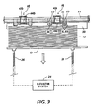
- the sheet stacking area comprises an elevator tray 22 which is movable downwardly as stacks are accumulated so as to maintain a relatively constant stacking level at the top of the stack for the incoming further sheets to be stacked.
- An automatic elevator lowering system 24 utilizing commonly driven screw jacks such as 26, and a stack level switch 28, or the like, controls the lowering of the elevator tray 22 by rotating the screw jacks 26 to maintain a substantially constant stacking level, by moving the elevator table 22 downwardly as the stack accumulates, and then moving the table 22 back up after the stacks are removed.
- the rapidly sequentially incoming sheets 12 to be stacked in the stacking area 20 are fed over the top of the stack towards a sheet lead edge registration wall 30 by a vacuum belt sheet transport system 40.
- a sheet 12 being transported by the vacuum belt system 40, approaches the lead edge registration wall 30, the sheet is peeled therefrom by a sheet peeling and normal force system 50, as will be further described.
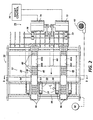
- Vacuum is provided to the sheet transport system 40 by vacuum manifolds or channels 42a and 42b (Fig.2), here provided with vacuum by a conventional vacuum blower system 43 (Fig.2) pneumatically connecting to the manifolds 42a and 42b by a cross manifold as illustrated, or any other suitable system.
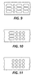
- the manifolds 42a, 42b extend above and support the lower flights of the vacuum belts 44a, 44b, which are spaced apart transversely across the sheet path to provide nonskewing, non-slip feeding of the sheets 12 through vacuum apertures 80 such as are shown in Fig. 2, or the alternative belt configurations of Figs. 4 - 11, or combinations of those features.
- the plural vacuum belts 44a, 44b are commonly driven by a motor M on a common shaft mounting of driven end rollers 45 so as to provide non-skewing feeding of the sheets acquired by this transport system 40.
- the motor M may be a conventional servo motor.
- the belt apertures are only in spaced apart aperture patterns, spaced along the belts, such as the aperture patterns 82 in Fig. 2.
- the vacuum belts are provided with such vacuum aperture areas in "pitches" corresponding to the dimensions of the sheets to be fed in their sheet transporting direction. This is because the sheets 12 are transported here by vacuum adhesion only of a lead edge area of each sheet. The spacing between vacuum aperture areas along the belt is thus set for the dimension of sheets to be fed in their process direction.
- Fig. 6 shows a preferred vacuum aperture pattern with hole patterns spaced about 13 inches (33 cm) apart. With this hole pattern, the "length" of the fed sheet is the standard 8.5 inches (21.6 cm) and there is 4.5 inches (11.4 cm) between sheets.
- a 17 inch (43.2 cm) sheet would cover two succeeding such hole patterns. When a 17 inch (43.2 cm) sheet reached the registration wall, the lead edge would peel off but the second hole pattern would continue to push the trailing edge of the sheet forward, causing the sheet to buckle and jam under the weighted roller.
- the dual pitch belt shown in Fig. 7 would be an alternate configuration.
- a two part manifold would be provided. Each part of the manifold would be connected to a different fan, or shunted to a single fan input via a solenoid operated valve (not shown). The belts shown in Fig.
- the hole patterns are 12 inches (30.5 cm) apart and 81 ⁇ 2 inch (21.6 cm) sheets can be acquired and driven to the registration wall.
- the intersheet gap here is 31 ⁇ 2 inches (8.9 cm).
- the right side of the manifold is turned off and sheets are acquired at every hole pattern on the left side of the belt.
- the hole patterns are 24 inches (61 cm) apart and 17 inch (43.2 cm) sheets are acquired and driven to the registration wall where they are released without being buckled.
- the intercopy gap here is 7 inches (17.8 cm).
- FIG. 8 Another configuration of belts is shown in Fig. 8. These belts have alternate hole patterns 12 inches (30.5 cm) apart on either edge of the belt. When operating with 17 inch (43.2 cm) sheets, vacuum pressure on the right side of the manifold is turned off and sheets are acquired by the 24 inch (61 cm) spaced holes on the left side of the belt. When operating with 81 ⁇ 2 inch (21.6 cm) sheets, both sides of the manifold are evacuated and sheets are acquired and driven forward by the alternating hole patterns on either edge of the belt.
- the incoming sheets must be synchronized to meet up with the positions of these belt apertures, such as by the drive motor M for the belts.
- each sheet 12 As the lead edge area of each sheet 12 enters the stacking area 20, it is thus vacuum acquired by a vacuum aperture pattern 82 of both belts 44a, 44b and vacuum adhered to both belts.
- the vacuum belt transport system 40 thus moves the sheet rapidly over the previously stacked sheets, above the sheets by a substantial spacing of the belt 44a, 44b lower flights above the top of the stack, as illustrated.
- an additional sheet trailing end support can be provided for particularly large sheets, if needed.
- a system 50 for automatically stripping off and controlling the lead edge of the sheet for stacking registration including slowing the sheet down just before its impact with the registration wall 30, so that the sheet lead edge will not be damaged or bounce away from the registration wall due to a high speed impact.
- this sheet peeling and normal force system 50 may be a simple, integral, yet automatically self-compensating system which cooperatively interacts with the vacuum belt system 40.
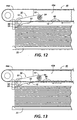
- the sheet peeling and normal force system 50 comprises plural independent stripper and wheel units 51, which are each pivotally mounted closely adjacent to, and on opposite sides of, the belts 44a, 44b, and adjacent to the sheet lead edge registration wall 30.
- Each stripper unit 51 has a predetermined low impact angle lower sheet guide surface 52 extending from above to below the level or plane of the lower flights of the vacuum belts 44a, 44b.
- the lead edge of the sheet strikes these guide surfaces 52, which guide and pulls the lead edge of the sheet away from the vacuum belts 44a, 44b and directs the lead edge of the sheet downwardly toward the top of the sheet stack.
- These guide surfaces 52 extend continuously and smoothly down from the point of impact of the sheets in the plane of the vacuum belts 44a, 44b to closely adjacent the stacking level.
- Each unit 51 is also freely pivotally mounted at its upper or pivot end 53 to a pivot support rod 54 above this vacuum belt sheet transport plane.
- the opposite or free end of each unit 51 is a wheel end 55, which mounts a weighted roller or wheel 56.
- the entire unit 51 is thus gravity loaded against the top of the stack with the rollers 56 resting upon the top sheet of the stack with a predetermined weight built into the unit 51 and its end roller 56. This weight is designed to provide a predetermined normal force.
- the sheet 12 being peeled off slides down the guide surfaces 52 of the stripper units 51, it is driven under the rollers 56 and onto the top of the stack in its final movement towards the closely adjacent end stop at the registration wall 30.
- This not only holds down the lead edge of the sheet flatly against the top of the stack (in spite of any curl in the sheet), it also provides inter-sheet friction due to this normal force pressing down the incoming sheet lead edge against the previous sheet on the top of the stack. This helps reduce the sheet velocity and to prevent "bounce back" as the lead edge of the sheet strikes the registration wall 30.
- the rollers 56 are smooth and freewheeling, to provide normal force without forward sheet feeding resistance thereunder. The wheel 56 tangent transitions smoothly from the guide surface 52, so the guide surface 52 guides the sheet lead edge directly under the wheel surface.
- the vacuum belt sheet transport system 50 continues to apply vacuum adhesion driving force on the lead edge area of the sheet as it is being stripped, but with decreasing vacuum area engagement and drive force as the stripping continues. This is provided for by the area (extending along the belt) of the vacuum apertures 80 in the pattern 82. It may be seen that the area of the vacuum aperture patterns 82 extending along the belts 44a, 44b is in pattern dimensions corresponding roughly to the sheet stripping distance along the stripper guide surfaces 52.
- each sheet of paper's lead edge is positively clamped down on top of the stack without any settling time delays or any curled paper effects.
- No positive air pressure is required anywhere in this system, for sheet settling, for removal of sheets from the vacuum transport, or otherwise.
- the incoming sheet is not blown off, nor does it require a scuffer sled or a mechanical knockdown system, or any other critically actuated timing system.
- No moving mechanism is required other than a very slight passive pivoting movement of the stripping arm units 51, and rotation of their rollers 56 at the outer ends 55 thereof. (In some cases, the rollers 56 do not even need to rotate.) All of that is accomplished by the incoming sheet movement itself, without any requirement of any drive or mechanism.
- movable sheet end supports 60 which can be axially or pivotally temporarily inserted between the top of the sheet stack and the plane of the transporting belt flights 44a, 44b in the rear or upstream portion of the stacking area 20, so as to hold up the trailing portions of such a special sheet which might otherwise exert excessive frictional drag on the previous top sheet of the stack.
- the movable end supports 60 may be effectively "swing arm guides" which swing in to prevent the incoming lead edge of the next sheet from jamming into the trail edges of previous sheets that have not fully settled out of the path of the incoming sheet lead edge.
- the incoming sheets in the sheet output path 16 may be gated from that output path 16 by a conventional deflector finger gate 62 or the like, in order to be stacked by the system 10.
- the gate 62 is down or out of the output path 16 the sheets may be fed directly on to a subsequent such module, or on to an output stacking tray without inversion, a purge tray, a bookbinder or other finisher, or the like. It will be appreciated, however, that integral finishing may also be provided in the stacking and registration system 10 itself, if desired.
- a natural arcuate inversion path 66 is provided to turn over the sheets in a semi-cylindrical path, so that they may be stacked inverted from their original output orientation from the reproduction machine 14, as is often desired.
- This natural or unidirectional arcuate inversion path 66 with a large radius provides a low jam rate as compared to inverters which require rapidly reversing the direction of motion of a sheet and changing its lead to trail edge position and path direction.
- Such inverters must rapidly decelerate and reaccelerate the sheet, since they are not unidirectional. That has disadvantages, such as potentially inducing sheet skew and/or skippage, etc..
- the sheet 12 continues in its same direction of movement at the same basic high velocity, yet is effectively inverted.
- the arcuate inversion path 66 desirably provides an additional integral function, of sheet lateral registration and/or offsetting, utilizing the upstream feeding and registration system 70.
- the upstream feeding and registration system 70 comprises independent servo motors 72 and 74 driving opposite sides of the sheet 12 by roller nips 77, 78 in the inversion path 66. This allows deskewing and lateral registration of the sheet to be done in a known manner, illustrated here by the offset control 76, shown in Fig. 2, differently driving the two servo motors, so as to achieve deskew and registration as the sheets pass through their respectively driven roller nips 77, 78.
- This electronically controlled nip pair 77, 78 "steers” the sheet to one side or the other for electronic offsetting as well as deskewing of the sheet.
- these electronically controlled nips 77, 78 can provide lead edge timing in the process direction of the sheet (speedup or slowdown) to coincide with the arrival of one of the three or more pitched areas of hole patterns in the vacuum transport belts 44a, 44b at the output of the upstream feeding and registration system 70.
- Conventional sheet edge position path sensors may be used in conjunction therewith. As indicated above, this is merely one form of such optional side or lateral registration system which can be utilized here. Such side registration is desirably done while the sheet is in such an arcuate path such as 66 here, since this provides substantially increased beam strength for the sheet, improving the lateral registration capability.
- the sheets 12 can enter the stacking and process direction registration system 10 from the upstream feeding and registration system 70 already correctly laterally positioned and deskewed.
- the non-slip transport system 40 then maintains this proper orientation of the sheets so that deskewing does not have to be done by impact of the lead edge of the sheet at an angle with the registration wall 30, as in many other stacking systems. That would be particularly undesirable for high speed stacking, because the sheet lead edge would concentrate its impact force on one corner of the sheet, which can damage it, rather than uniformly spreading the lead edge impact force along the sheet lead edge.
- the upstream feeding and registration system 70 can provide deliberately different lateral positioning of incoming sheets, so that different job sets can be stacked laterally offset from one another on the table 22.
- Such lateral offsetting of job sets is well known and desirable for customer job separation and distinction. Providing such lateral offsetting upstream eliminates any need for tamping of sheets within the stacking area, which could interfere with other registration and stacking requirements.
- the belt configurations of the belts of Figs. 4 and 5 provide corrugation at 90 or 92 along the sheet 12 to add some beam strength to the sheet in its transporting direction and thereby help hold up the upstream portions of the sheet which are not vacuum supported.
- the upper and lower flights of the belt would be flat and would acquire and transport the sheet as described.
- the upper and lower flights of the belt would be slightly curled in the lateral direction. This curvature serves two purposes. It imparts a slight corrugation to the sheet transverse to the direction of motion which strengthens the sheet and helps drive it to the registration wall.
- the curvature helps hold the sheet to the belt by creating a vacuum pocket between the acquired sheet and the belt
- This pocket of low pressure air originates at the hole pattern in the belt at the lead edge and extends to the trailing edge of the sheet. This negative pressure in the pocket terminates when the belt holes pass the end of the manifold, thus releasing the sheet.
- the incoming sheets 12 are gently peeled by the ramps 52 and rollers 56 system from the incoming sheet vacuum transport belts 44a, 44b, while the remaining vacuum port area 82 engaging the sheet is being automatically reduced.
- This provides gradual reduction of the sheet drive adjacent the registration edge, yet the sheet removal from the vacuum transport belts is passive here, and the weighted rollers 56 also prevent bounceback when the lead edge of the sheet strikes the registration wall.
- the lead edge of each incoming sheet is positively fed all the way to directly on top of the sheet stack at the registration position, rather than flying and/or falling into place.
- the next sheet may be immediately acquired upstream and be fed over the stacking area towards the same registration position even before the prior sheet is registered.
- the final deceleration of the sheet is assisted by the disclosed passive, non-obstructive applied normal force by the weighted rollers 56 (which may alternatively be spring-loaded rather than weight-loaded, of course).
Landscapes
- Engineering & Computer Science (AREA)
- Mechanical Engineering (AREA)
- Registering Or Overturning Sheets (AREA)
- Pile Receivers (AREA)
- Paper Feeding For Electrophotography (AREA)
- Delivering By Means Of Belts And Rollers (AREA)
- Separation, Sorting, Adjustment, Or Bending Of Sheets To Be Conveyed (AREA)
Claims (9)
- Système d'empilement et de positionnement de feuilles (10) avec une zone d'empilement de feuilles (20) destiné à empiler en séquence les feuilles imprimées légères (12) délivrées en sortie d'un appareil de reproduction (14) alimentant en séquence ladite zone d'empilement de feuilles (20), avec un système de positionnement de bord définissant une position de positionnement d'empilement de bord avant de feuille (30), comprenant :caractérisé en ce queun transport de feuilles par courroie sous vide (40) pourvu d'ouvertures de vide (80) pour saisir par le vide lesdites feuilles alimentant ladite zone d'empilement de feuilles (20) et pour transporter lesdites feuilles saisies par-dessus ladite zone d'empilement de feuilles (20), au-dessus des feuilles précédemment empilées à l'intérieur, vers ladite position de positionnement d'empilage de bord avant de feuille (30) dudit système de positionnement de bord ;un système de pelage de feuille (50, 52) pour peler les bords avant desdites feuilles dudit transport de feuilles par courroie sous vide (40) de façon adjacente à ladite position de positionnement de bord avant de feuilles (30) et pour guider ledit bord avant de feuille pelée vers le bas et vers ladite position de positionnement d'empilement de bord avant de feuilles (30) ; etun système à force normale (50, 56) associé fonctionnellement audit système de pelage de feuilles (50, 52) pour presser vers le bas les bords avant desdites feuilles pelées contre lesdites feuilles précédemment empilées dans ladite zone d'empilement de feuilles (20) lorsque les bords avant desdites feuilles atteignent ladite position de positionnement de bord avant de feuille (30) ;lesdites ouvertures de vide (80) sont positionnées en motifs (82) espacés entre des zones sensiblement non ouvertes le long dudit transport de feuilles par courroie sous vide (40) de façon à ne mettre en prise que les zones en séquence de bord avant de feuille ; etladite prise par le vide desdites feuilles est automatiquement réduite en diminuant graduellement la zone de prise par le vide desdites feuilles par lesdites ouvertures de vide (80) de la courroie pendant le temps durant lequel ledit bord avant de feuille est en cours de pelage par ledit système de pelage de feuille (50, 52) à partir dudit transport de feuilles par courroie sous vide (40).
- Système d'empilement et de positionnement de feuilles selon la revendication 1, dans lequel ledit transport de feuilles par courroie sous vide (40) continue à transporter lesdites feuilles tout en réduisant ladite prise par le vide de celles-ci à mesure que les feuilles sont pelées depuis celui-ci par ledit système de pelage de feuilles (50, 52) de façon qu'une commande d'alimentation partielle au moins soit maintenue sur lesdites feuilles pendant que lesdites feuilles alimentent ladite position de positionnement d'empilement de bord avant de feuille (30).
- Système d'empilement et de positionnement de feuilles selon les revendications 1 ou 2, dans lequel lesdites feuilles alimentant en séquence ladite zone d'empilement de feuilles (20) alimentent celle-ci par un système d'alimentation et de positionnement en amont (70) qui positionne latéralement lesdites feuilles par un système de repositionnement de feuilles latéral avant que lesdites feuilles soient saisies par ledit transport de feuilles par courroie sous vide (40) ;et dans lequel ledit transport de feuilles par courroie sous vide (40) procure une alimentation sans glissement maintenant le positionnement desdites feuilles dans ledit système de pelage de feuilles (50, 52).
- Système d'empilement et de positionnement de feuilles selon l'une quelconque des revendications précédentes dans lequel ledit système de pelage de feuilles (50,52) et ledit système à force normale (50, 56) associé comprennent plusieurs éléments de guidage de feuilles pivotants (52) munis de galets d'extrémités (56), lesdits éléments de guidage de feuilles croisant fonctionnellement ledit transport de feuilles par courroie sous vide (40) selon un angle de dégarnissage afin de dégarnir lesdites feuilles dudit transport de feuilles par courroie sous vide (40), lesdits éléments de guidage de feuilles (52) procurant un trajet lisse de guidage de feuilles en dessous à partir dudit transport de feuilles par courroie sous vide (40) jusqu'aux dits galets d'extrémités (56), lesdits galets d'extrémités (56) procurant ladite force normale contre lesdites feuilles pour ralentir par friction lesdites feuilles à mesure qu'elles approchent de ladite position de positionnement d'empilement de bord avant de feuille (30), et lesdits galets d'extrémités (56) procurant également ladite force normale pour maintenir vers le bas lesdites feuilles après qu'elles ont atteint ladite position de positionnement d'empilement de bord avant de feuille (30).
- Système d'empilement et de positionnement de feuilles selon l'une quelconque des revendications précédentes dans lequel :ledit transport de feuilles par courroie sous vide (40) comprend plusieurs courroies sous vide espacées parallèles (44a, 44b) avec des collecteurs sous vide superposés (42a, 42b) ;lesdites courroies sous vide présentant lesdits motifs d'ouvertures de vide (80) espacés entre des zones sensiblement sans ouverture le long desdites courroies sous vide (44a, 44b) de façon à se mettre en prise seulement. avec des zones de bord avant de feuilles en séquence ;lesdites ouvertures de vide (80) de courroies étant fournies fonctionnellement en vide provenant desdits collecteurs de vide superposés (42a, 42b) pour une alimentation de feuilles sans glissement par lesdites courroies sous vide (44a, 44b) ; etun système d'entraínement synchronisé (M, 45) entraínant lesdites courroies sous vide (44a, 44b) pour les mettre en prise de façon synchrone avec les zones de bord avant desdites feuilles alimentant en séquence ladite zone d'empilement de feuilles (20) ; et de préférence dans lequel ledit transport de feuilles par courroie sous vide (40) diminue graduellement la zone de prise par le vide d'une feuille par lesdites ouvertures de vide (80) de courroie pendant le temps durant lequel le bord avant de la feuille est pelé desdites courroies sous vide (44a, 44b) par ledit système de pelage (50, 52).
- Système d'empilement et de positionnement de feuilles selon l'une quelconque des revendications précédentes, comprenant de plus un système de guidage support mobile de feuille (60), mobile en partie au-dessus de ladite zone d'empilement de feuilles (20) et en partie au-dessous dudit transport de feuilles par courroie sous vide (40), en amont dudit système de pelage de feuille (50, 52) pour supporter au moins en partie les zones d'extrémité arrière des feuilles transportées par ledit transport de feuilles par courroie sous vide (40) par lesdites zones de bord avant limitées desdites feuilles.
- Système d'empilement et de positionnement de feuilles selon l'une quelconque des revendications précédentes, dans lequel ledit système à force normale (50, 56) est intégré en une seule partie avec ledit système de pelage de feuilles (50, 52), et ledit système de pelage de feuilles et à force normale intégré (50, 52, 56) pivote par gravité sur la feuille du haut de ladite zone d'empilement de feuilles (20) de façon étroitement adjacente à ladite position de positionnement d'empilement de bord avant de feuille (30) ; etdans lequel ledit système intégré de pelage de feuille à force normale (50, 52, 56) est monté de façon pivotante (54) au niveau d'une extrémité (53) au-dessus dudit transport de feuilles par courroie sous vide (40) et présente un galet d'extrémité (56) monté au niveau de son extrémité libre opposée (55) afin de presser contre la feuille du haut empilée dans ladite zone d'empilement de feuilles (20).
- Système d'empilement et de positionnement de feuilles selon l'une quelconque des revendications précédentes, dans lequel ledit transport de feuilles par courroie sous vide (40) comprend plusieurs courroies sous vide sans fin allongées, étroites, espacées (44a, 44b), présentant des motifs (82) d'ouvertures de vide (80) espacés dans lesdites dimensions allongées, et dans lequel lesdites courroies sous vide (44a, 44b) sont concaves (92) par rapport auxdites feuilles saisies pour se mettre en prise avec lesdites feuilles saisies au niveau des bords externes desdites courroies sous vide (44a, 44b) afin de procurer une poche sous vide entre lesdites courroies sous vide (44a, 44b) et lesdites feuilles saisies, et pour procurer une ondulation limitée desdites feuilles.
- Système d'empilement et de positionnement de feuilles selon l'une quelconque des revendications précédentes, dans lequel ledit système de positionnement de bord comprend une paroi de positionnement sensiblement verticale, et dans lequel lesdites courroies sous vide (44a, 44b) dudit transport de feuilles par courroie sous vide (40) entrecroisent ladite paroi verticale en dessous du sommet de ladite paroi de positionnement.
Applications Claiming Priority (2)
| Application Number | Priority Date | Filing Date | Title |
|---|---|---|---|
| US457938 | 1995-06-01 | ||
| US08/457,938 US5671920A (en) | 1995-06-01 | 1995-06-01 | High speed printed sheet stacking and registration system |
Publications (3)
| Publication Number | Publication Date |
|---|---|
| EP0745546A2 EP0745546A2 (fr) | 1996-12-04 |
| EP0745546A3 EP0745546A3 (fr) | 1998-01-07 |
| EP0745546B1 true EP0745546B1 (fr) | 2002-02-06 |
Family
ID=23818668
Family Applications (1)
| Application Number | Title | Priority Date | Filing Date |
|---|---|---|---|
| EP96303899A Expired - Lifetime EP0745546B1 (fr) | 1995-06-01 | 1996-05-30 | Système d'empilage et de positionnement à grande vitesse de feuilles imprimées |
Country Status (5)
| Country | Link |
|---|---|
| US (1) | US5671920A (fr) |
| EP (1) | EP0745546B1 (fr) |
| JP (1) | JPH08324867A (fr) |
| CA (1) | CA2172194C (fr) |
| DE (1) | DE69619023T2 (fr) |
Families Citing this family (44)
| Publication number | Priority date | Publication date | Assignee | Title |
|---|---|---|---|---|
| US5882175A (en) * | 1997-01-13 | 1999-03-16 | Ward Holding Company | Stacker for flexible sheets |
| US5904465A (en) * | 1997-01-13 | 1999-05-18 | Ward Holding Company | Stacker with discharge control |
| DE19722956B4 (de) * | 1997-05-31 | 2004-05-06 | Koenig & Bauer Ag | Verfahren zur exakten Stapelbildung in Bogenauslegern von Druckmaschinen und Bogenausleger zur Durchführung des Verfahrens |
| JPH11255392A (ja) * | 1998-03-09 | 1999-09-21 | Isowa Corp | シートスタッカのシート積上げ装置、サクションコンベア及びサクションベルト |
| DE19835003A1 (de) * | 1998-08-03 | 2000-02-10 | Heidelberger Druckmasch Ag | Ausleger für eine Druckmaschine |
| US6612570B1 (en) | 1999-06-07 | 2003-09-02 | William A. Cox | High speed stacking apparatus |
| CH693989A5 (fr) * | 2000-05-12 | 2004-05-28 | Bobst Sa | Dispositif de freinage d'une machine de travail d'éléments en feuilles. |
| EP1326796B1 (fr) | 2000-10-10 | 2005-02-02 | GRONBJERG, Ib | Empileur pour produits decoupes a l'emporte-piece |
| EP1247771B1 (fr) * | 2001-04-03 | 2004-12-08 | Mars Incorporated | Magasin pour des billets de banque |
| DE10127452A1 (de) * | 2001-06-07 | 2002-12-12 | Will E C H Gmbh & Co | Verfahren und Vorrichtung zum Ansammeln von Bogen zu Stapeln an einer Stapelablage |
| US6848688B1 (en) | 2003-09-08 | 2005-02-01 | Xerox Corporation | Automatically elevating sheet tamper and sheet input level for compiling large printed sets |
| US7395527B2 (en) | 2003-09-30 | 2008-07-01 | International Business Machines Corporation | Method and apparatus for counting instruction execution and data accesses |
| US8381037B2 (en) | 2003-10-09 | 2013-02-19 | International Business Machines Corporation | Method and system for autonomic execution path selection in an application |
| US7415705B2 (en) | 2004-01-14 | 2008-08-19 | International Business Machines Corporation | Autonomic method and apparatus for hardware assist for patching code |
| US7895382B2 (en) | 2004-01-14 | 2011-02-22 | International Business Machines Corporation | Method and apparatus for qualifying collection of performance monitoring events by types of interrupt when interrupt occurs |
| DE102004051243A1 (de) * | 2004-10-20 | 2006-05-04 | Bhs Corrugated Maschinen- Und Anlagenbau Gmbh | Stapel-Vorrichtung für Wellpappe-Bögen |
| DE102005055364A1 (de) * | 2005-11-17 | 2007-05-24 | Kba-Metronic Ag | Vorrichtung und Verfahren zum Fördern bogenförmiger Objekte |
| EA013584B1 (ru) | 2006-03-10 | 2010-06-30 | Ти-Би-Эс Энджиниринг Лимитед | Устройство для размещения аккумуляторных пластин |
| JP4311756B2 (ja) * | 2006-09-06 | 2009-08-12 | キヤノン株式会社 | シート積載装置と画像形成装置 |
| JP4838671B2 (ja) * | 2006-09-07 | 2011-12-14 | キヤノン株式会社 | シート搬送装置、シート積載装置及び画像形成装置 |
| US7954818B2 (en) * | 2006-12-28 | 2011-06-07 | Canon Kabushiki Kaisha | Sheet stacking apparatus and image forming apparatus |
| US8083462B2 (en) | 2007-04-11 | 2011-12-27 | Tbs Engineering Limited | Apparatus for placing battery plates in a line |
| JP4924216B2 (ja) * | 2007-06-06 | 2012-04-25 | コニカミノルタビジネステクノロジーズ株式会社 | 画像形成システム |
| SE0701892L (sv) * | 2007-08-20 | 2009-01-13 | Lasermax Roll Systems Ab | Anordning för stapling av ark |
| JP5031530B2 (ja) * | 2007-11-20 | 2012-09-19 | キヤノン株式会社 | シート積載装置及び画像形成装置 |
| US7866292B2 (en) * | 2008-03-26 | 2011-01-11 | AES Industries Inc | Apparatus and methods for continuous variable valve timing |
| US7913999B2 (en) * | 2008-06-12 | 2011-03-29 | Xerox Corporation | Resilient belt sheet compiler with mixed sheet length mode |
| JP4762293B2 (ja) * | 2008-10-31 | 2011-08-31 | 株式会社東芝 | 紙葉類搬送装置 |
| JP4891385B2 (ja) * | 2008-12-26 | 2012-03-07 | キヤノン株式会社 | シート積載装置と画像形成装置 |
| US8800753B2 (en) | 2009-09-10 | 2014-08-12 | Bdt Media Automation Gmbh | System for conveying an article using vortex suction units |
| US9079733B2 (en) | 2010-05-07 | 2015-07-14 | Bdt Media Automation Gmbh | Vortex suction separator device |
| US8186668B2 (en) | 2010-10-07 | 2012-05-29 | Bdt Ag | Stack feeding aeration device and method |
| WO2012107217A2 (fr) | 2011-02-11 | 2012-08-16 | Bdt Media Automation Gmbh | La présente invention porte sur un système d'aspiration et de transport pour aspirer et transporter un objet |
| US8919766B1 (en) | 2014-01-23 | 2014-12-30 | Xerox Corporation | Compiler shelf having rotatable CAM with high-friction lobe |
| US9821978B2 (en) * | 2016-03-23 | 2017-11-21 | Xerox Corporation | Sheet stacking system for flimsy sheets |
| US9758334B1 (en) | 2016-08-18 | 2017-09-12 | Xerox Corporation | Corrugating baffle for on stack finishing system |
| CN107934571B (zh) * | 2017-08-11 | 2024-06-14 | 南通思瑞机器制造有限公司 | 一种皮革码垛系统 |
| EP3677102B1 (fr) * | 2017-12-13 | 2024-11-06 | Hewlett-Packard Development Company, L.P. | Procédé et système d'empilement de substrats imprimés |
| JP7081275B2 (ja) * | 2018-03-30 | 2022-06-07 | セイコーエプソン株式会社 | 媒体処理装置、後処理装置 |
| DE102019102774A1 (de) * | 2019-02-05 | 2020-08-06 | Koenig & Bauer Ag | Bogenauslage, eine Bogenbearbeitungsmaschine und ein Verfahren zum Betreiben einer Bogenbearbeitungsmaschine |
| US11198580B2 (en) | 2019-09-06 | 2021-12-14 | Xerox Corporation | Stacking module with air streams |
| EP4005958B1 (fr) * | 2020-11-27 | 2023-07-12 | Canon Production Printing Holding B.V. | Empileuse de feuille comprenant un dispositif de retournement de feuille et dispositif de support |
| IT202100016211A1 (it) * | 2021-06-21 | 2022-12-21 | Tecnau Srl | Equipaggiamento per impilamento fogli |
| IT202100016238A1 (it) * | 2021-06-21 | 2022-12-21 | Tecnau Srl | Equipaggiamento per impilamento ad alta velocità di fogli cartacei |
Family Cites Families (10)
| Publication number | Priority date | Publication date | Assignee | Title |
|---|---|---|---|---|
| US3123354A (en) * | 1964-03-03 | Transporting and stacking sheet-like articles | ||
| CH363666A (de) * | 1958-04-14 | 1962-08-15 | Champlain Company Inc | Verfahren und Einrichtung zum Befördern und Aufstapeln von biegsamen, blatt- oder folienartigen Teilen |
| US3328027A (en) * | 1965-05-24 | 1967-06-27 | Joachim G Schmidtke | Sheet delivery unit |
| GB1109130A (en) * | 1965-07-05 | 1968-04-10 | Hamilton Tool Co | Apparatus for conveying sheet material |
| US3905487A (en) * | 1974-03-04 | 1975-09-16 | Greene Line Mfg Corp | Continuous stacking apparatus |
| US4157177A (en) * | 1975-12-10 | 1979-06-05 | Dr. Otto C. Strecker Kg. | Apparatus for converting a stream of partly overlapping sheets into a stack |
| US4436301A (en) * | 1981-11-02 | 1984-03-13 | Xerox Corporation | Document restack transport |
| US4971304A (en) * | 1986-12-10 | 1990-11-20 | Xerox Corporation | Apparatus and method for combined deskewing and side registering |
| US5172904A (en) * | 1991-09-10 | 1992-12-22 | Xerox Corporation | Sheet stacking apparatus with angled sheet transport belts |
| DE4305579A1 (de) * | 1993-02-24 | 1994-08-25 | Will E C H Gmbh & Co | Vorrichtung zum Ansammeln von Papierbogen |
-
1995
- 1995-06-01 US US08/457,938 patent/US5671920A/en not_active Expired - Lifetime
-
1996
- 1996-03-20 CA CA002172194A patent/CA2172194C/fr not_active Expired - Fee Related
- 1996-05-24 JP JP8129696A patent/JPH08324867A/ja not_active Withdrawn
- 1996-05-30 EP EP96303899A patent/EP0745546B1/fr not_active Expired - Lifetime
- 1996-05-30 DE DE69619023T patent/DE69619023T2/de not_active Expired - Fee Related
Also Published As
| Publication number | Publication date |
|---|---|
| US5671920A (en) | 1997-09-30 |
| DE69619023T2 (de) | 2002-06-20 |
| EP0745546A2 (fr) | 1996-12-04 |
| JPH08324867A (ja) | 1996-12-10 |
| CA2172194A1 (fr) | 1996-12-02 |
| CA2172194C (fr) | 1999-01-12 |
| EP0745546A3 (fr) | 1998-01-07 |
| DE69619023D1 (de) | 2002-03-21 |
Similar Documents
| Publication | Publication Date | Title |
|---|---|---|
| EP0745546B1 (fr) | Système d'empilage et de positionnement à grande vitesse de feuilles imprimées | |
| US4469319A (en) | Large document restacking system | |
| US5303017A (en) | Print skip avoidance for on-line compiling | |
| DE69412367T2 (de) | Blattpuffersystem | |
| US5008713A (en) | Sheet conveying apparatus and sheet conveying method | |
| EP0576235B1 (fr) | Dispositif à plusieurs modes de sortie pour feuilles, par déplacement angulaire de la ligne de contact, pour empilement recto ou verso | |
| US5409202A (en) | Integral disk type inverter-stacker and stapler | |
| US5409201A (en) | Integral disk type inverter-stacker and stapler with sheet stacking control | |
| US6817609B2 (en) | Printer sheet lateral registration system with automatic upstream nip disengagements for different sheet size | |
| US5476256A (en) | Disk stacker including passive sheet registration assist system | |
| JP3647179B2 (ja) | シート収納・整合装置及び製本装置 | |
| US4789150A (en) | Sheet stacking apparatus with trail edge control flaps | |
| US5114135A (en) | Disk stacker including registration assist device | |
| JPH0664370B2 (ja) | 書類シート送り・位置決め装置 | |
| JP2912048B2 (ja) | シート取扱装置 | |
| JPH0762768B2 (ja) | 書類シートの送り及び位置決め装置 | |
| US6443450B1 (en) | Sheet stacking apparatus and method | |
| US7172187B2 (en) | Waiting tray for sheet processing tray | |
| US5447303A (en) | Sheet inverter apparatus | |
| EP0673868B1 (fr) | Dispositif de retournement et d'empilage à disque avec une agrafeuse intégrée | |
| US5065996A (en) | Disk stacker including movable gate for insertion of sheets into disk slots | |
| JP4065506B2 (ja) | シート処理装置及び画像形成装置 | |
| JPH08137151A (ja) | シート後処理装置 | |
| USH1781H (en) | Automatically retractable extending nip sheet ejection system for a multiple output locations stacking device | |
| JPH019797Y2 (fr) |
Legal Events
| Date | Code | Title | Description |
|---|---|---|---|
| PUAI | Public reference made under article 153(3) epc to a published international application that has entered the european phase |
Free format text: ORIGINAL CODE: 0009012 |
|
| AK | Designated contracting states |
Kind code of ref document: A2 Designated state(s): DE FR GB |
|
| PUAL | Search report despatched |
Free format text: ORIGINAL CODE: 0009013 |
|
| AK | Designated contracting states |
Kind code of ref document: A3 Designated state(s): DE FR GB |
|
| 17P | Request for examination filed |
Effective date: 19980707 |
|
| 17Q | First examination report despatched |
Effective date: 20000223 |
|
| GRAG | Despatch of communication of intention to grant |
Free format text: ORIGINAL CODE: EPIDOS AGRA |
|
| GRAG | Despatch of communication of intention to grant |
Free format text: ORIGINAL CODE: EPIDOS AGRA |
|
| GRAH | Despatch of communication of intention to grant a patent |
Free format text: ORIGINAL CODE: EPIDOS IGRA |
|
| GRAH | Despatch of communication of intention to grant a patent |
Free format text: ORIGINAL CODE: EPIDOS IGRA |
|
| GRAA | (expected) grant |
Free format text: ORIGINAL CODE: 0009210 |
|
| REG | Reference to a national code |
Ref country code: GB Ref legal event code: IF02 |
|
| AK | Designated contracting states |
Kind code of ref document: B1 Designated state(s): DE FR GB |
|
| REF | Corresponds to: |
Ref document number: 69619023 Country of ref document: DE Date of ref document: 20020321 |
|
| ET | Fr: translation filed | ||
| PLBE | No opposition filed within time limit |
Free format text: ORIGINAL CODE: 0009261 |
|
| STAA | Information on the status of an ep patent application or granted ep patent |
Free format text: STATUS: NO OPPOSITION FILED WITHIN TIME LIMIT |
|
| 26N | No opposition filed |
Effective date: 20021107 |
|
| PGFP | Annual fee paid to national office [announced via postgrant information from national office to epo] |
Ref country code: FR Payment date: 20040510 Year of fee payment: 9 |
|
| PGFP | Annual fee paid to national office [announced via postgrant information from national office to epo] |
Ref country code: GB Payment date: 20040526 Year of fee payment: 9 |
|
| PGFP | Annual fee paid to national office [announced via postgrant information from national office to epo] |
Ref country code: DE Payment date: 20040610 Year of fee payment: 9 |
|
| PG25 | Lapsed in a contracting state [announced via postgrant information from national office to epo] |
Ref country code: GB Free format text: LAPSE BECAUSE OF NON-PAYMENT OF DUE FEES Effective date: 20050530 |
|
| PG25 | Lapsed in a contracting state [announced via postgrant information from national office to epo] |
Ref country code: DE Free format text: LAPSE BECAUSE OF NON-PAYMENT OF DUE FEES Effective date: 20051201 |
|
| GBPC | Gb: european patent ceased through non-payment of renewal fee |
Effective date: 20050530 |
|
| PG25 | Lapsed in a contracting state [announced via postgrant information from national office to epo] |
Ref country code: FR Free format text: LAPSE BECAUSE OF NON-PAYMENT OF DUE FEES Effective date: 20060131 |
|
| REG | Reference to a national code |
Ref country code: FR Ref legal event code: ST Effective date: 20060131 |