EP0747103B1 - Extracteur soxhlet pour extraction solide/liquide - Google Patents
Extracteur soxhlet pour extraction solide/liquide Download PDFInfo
- Publication number
- EP0747103B1 EP0747103B1 EP95810380A EP95810380A EP0747103B1 EP 0747103 B1 EP0747103 B1 EP 0747103B1 EP 95810380 A EP95810380 A EP 95810380A EP 95810380 A EP95810380 A EP 95810380A EP 0747103 B1 EP0747103 B1 EP 0747103B1
- Authority
- EP
- European Patent Office
- Prior art keywords
- valve
- vessel
- conduit
- extractor according
- extraction
- Prior art date
- Legal status (The legal status is an assumption and is not a legal conclusion. Google has not performed a legal analysis and makes no representation as to the accuracy of the status listed.)
- Expired - Lifetime
Links
Images


Classifications
-
- B—PERFORMING OPERATIONS; TRANSPORTING
- B01—PHYSICAL OR CHEMICAL PROCESSES OR APPARATUS IN GENERAL
- B01D—SEPARATION
- B01D11/00—Solvent extraction
- B01D11/02—Solvent extraction of solids
- B01D11/0215—Solid material in other stationary receptacles
- B01D11/0219—Fixed bed of solid material
-
- F—MECHANICAL ENGINEERING; LIGHTING; HEATING; WEAPONS; BLASTING
- F16—ENGINEERING ELEMENTS AND UNITS; GENERAL MEASURES FOR PRODUCING AND MAINTAINING EFFECTIVE FUNCTIONING OF MACHINES OR INSTALLATIONS; THERMAL INSULATION IN GENERAL
- F16K—VALVES; TAPS; COCKS; ACTUATING-FLOATS; DEVICES FOR VENTING OR AERATING
- F16K27/00—Construction of housing; Use of materials therefor
- F16K27/02—Construction of housing; Use of materials therefor of lift valves
- F16K27/0236—Diaphragm cut-off apparatus
-
- F—MECHANICAL ENGINEERING; LIGHTING; HEATING; WEAPONS; BLASTING
- F16—ENGINEERING ELEMENTS AND UNITS; GENERAL MEASURES FOR PRODUCING AND MAINTAINING EFFECTIVE FUNCTIONING OF MACHINES OR INSTALLATIONS; THERMAL INSULATION IN GENERAL
- F16K—VALVES; TAPS; COCKS; ACTUATING-FLOATS; DEVICES FOR VENTING OR AERATING
- F16K27/00—Construction of housing; Use of materials therefor
- F16K27/02—Construction of housing; Use of materials therefor of lift valves
- F16K27/029—Electromagnetically actuated valves
-
- F—MECHANICAL ENGINEERING; LIGHTING; HEATING; WEAPONS; BLASTING
- F16—ENGINEERING ELEMENTS AND UNITS; GENERAL MEASURES FOR PRODUCING AND MAINTAINING EFFECTIVE FUNCTIONING OF MACHINES OR INSTALLATIONS; THERMAL INSULATION IN GENERAL
- F16K—VALVES; TAPS; COCKS; ACTUATING-FLOATS; DEVICES FOR VENTING OR AERATING
- F16K7/00—Diaphragm valves or cut-off apparatus, e.g. with a member deformed, but not moved bodily, to close the passage ; Pinch valves
- F16K7/12—Diaphragm valves or cut-off apparatus, e.g. with a member deformed, but not moved bodily, to close the passage ; Pinch valves with flat, dished, or bowl-shaped diaphragm
- F16K7/14—Diaphragm valves or cut-off apparatus, e.g. with a member deformed, but not moved bodily, to close the passage ; Pinch valves with flat, dished, or bowl-shaped diaphragm arranged to be deformed against a flat seat
Definitions
- the invention relates to an extractor for solid-liquid extraction according to Soxhlet.
- a Solvent evaporated in a heatable distillation vessel and via a steam line into one above the still arranged extraction vessel guided.
- the Extraction vessel is used to hold the extract Material and extract provided and with a cooler trained to condense the extraction or solvent.
- the invention has for its object an extractor initially mentioned type with individual control of the Extract return to create different amounts of solvents can be used for distillation.
- the extractor arrangement should be simple be clean and represent an inert system.
- the return line can be opened or closed by means of a valve getting closed. If the solvent level is the desired one The valve can be opened and the extract flows into the distillation vessel. The Valve enables control of the extraction process different parameters. The gradient ensures that the entire extract is removed in each case.
- the closing element is advantageous via electromagnetic Activated means, which are attached to the housing.
- Conceivable but are also pneumatic, hydraulic or mechanical Control devices and in certain cases that could Closing element can also be operated manually.
- the extraction vessel and the return line as a one-piece glass set trained and the valve has connecting pieces with which it is melted directly into the return line.
- Such an arrangement is particularly suitable for use in laboratory area where extractors are cleaned periodically or need to be sterilized.
- the valve with at least one is particularly advantageous Derivation and at least one supply line provided with communicate with a valve chamber in which at least a valve seat is arranged.
- the valve has a closing element that is connected to the valve seat sealingly interacts and which from the outside the valve chamber can be activated.
- valve is particularly advantageous, the valve chamber partly by a homogeneous valve body made of glass, on which a valve seat is made in one piece is formed, each of a nozzle for the supply line and for the derivation.
- the valve body is detachably held in a housing that the rest of the valve chamber encloses.
- the closing element has a membrane, its edge area tight and sealing between the valve body and the Housing is clamped, there is a hermetic separation reached between supply and discharge.
- the membrane is the only component that exposed to the medium flowing through in the valve chamber is.
- the membrane can consist of an elastic Material exist, but it can also in particular in the edge area be relatively rigid.
- valve body approximately cylindrical and the housing approximately pot-shaped is formed and has lateral slots through which the sockets emerge from the housing, leaving the valve body with a cap that can be placed on the housing is fixable.
- the valve body thus also serves as Bracket for the housing, on which, if necessary, another Control device is attached.
- a Membrane can be the valve seat as a conical mouth be formed on an end face of the valve body.
- the membrane lies on the muzzle cone on a relative small circular area, with a high surface pressure is achieved.
- the valve seat could too have other shapes, especially if as a closing element a ball or a cone is used.
- agents that are particularly advantageous Extraction vessel are arranged and which to determine the Serve liquid levels. Once the liquid level the means send a signal with which the valve can be opened. After a predetermined time or when the extraction vessel is empty the valve closed again.
- the Means for measuring the solvent level can also be attached to this riser.
- Different liquid levels can be used at the agent Rising pipe can be arranged to be movable.
- a light barrier arrangement is particularly suitable as a means.
- the strength of the of the receiver element changes detected light and the light barrier arrangement sends a signal to open the valve.
- a float arrangement or an inductive measurement conceivable.
- a particularly advantageous construction of the extraction vessel arises when the riser is at its lower End directly and above the valve in the return line flows.
- Such an arrangement has the particular advantage that that for the riser and the return line only a common exit from the extraction vessel is provided must become.
- the extraction vessel can be used to carry out hot extractions additionally have a separate heating device.
- a temperature sensor is arranged on the distillation vessel.
- the valve can be controlled via the determined temperature. This is to ensure that the valve is only at Reaching a certain temperature of the extract Material is opened.
- the distillation vessel has an inert gas connection.
- inert gas By adding inert gas can the Exhaktoranowski
- FIG. 1 shows an extractor 21 with a valve 1 provided reflux line 26.
- the extractor 21 has a distillation vessel 22, in which with the help of a heater 30 an extractant can be heated to boiling.
- the Extractant rises as steam through the steam pipe 29 is condensed on the cooler 23 and drips into the extraction vessel 24.
- the substance to be extracted is in an extraction sleeve 25 filled with a permeable bottom. From a return line leads to the lower end of the extraction vessel 24 26 back to the distillation vessel 22.
- the reflux line 26 is run along its entire length with a slope and opens into distillation vessel 22 with its free end.
- a riser runs parallel to the extraction vessel 24 27, which has the same liquid level as in Extraction vessel 24.
- Fixed or adjustable means 28 for determining the liquid level arranged in the form of a light barrier.
- the light barrier arrangement 32 consists of a transmitter element 33 and a receiver element 34 ( Figure 2) which are opposite each other are arranged on the riser 27.
- the light barrier arrangement 32 is with a holding device 41 on a guide rail arranged parallel to the riser 27 42 movably attached.
- the guide rail 42 is rectangular and is with a slot 43 extending from bottom to top.
- An opening is recessed in the holding device 41, in which the guide rail 42 can be inserted.
- the light barrier arrangement 32 transmits a signal to a control device 40, which in turn sends a signal to open valve 1. This will the extraction vessel 24 emptied once the solvent level has reached a setpoint determined by the user. In this way you can work with small amounts of solvent without going through the jack given, fixed deduction level can be achieved got to.
- the extraction vessel is equipped to carry out hot extractions 24 in its lower part via a separate one Heating device 37. This allows the material to be extracted heated to a desired temperature, causing the Intensity of the extraction process is increased.
- a temperature sensor 38 determines the temperature of the separate heater 37 in the lower area of the extraction vessel and sends a signal to the control device 40.
- the control device 40 can be programmed so that the valve is only opened if next to the setpoint of the liquid level 39 also a target temperature of the separate heating device 37 is reached. Another parameter for the Valve control results when a temperature sensor 38 for Measuring the temperature of the heater 30 of the still 22 is used.
- control device 40 can be programmed in this way that the temperature sensors 38 measured temperatures for controlling the valve 1 not be taken into account.
- the extraction vessel 24, the riser 27 and the return line 26 are made in one piece from glass. Here is the riser 27 with its lower end 35 on the Top of the return line 26 attached.
- An inert gas connection is provided to dry out the extractor arrangement 36 provided, which is formed on the distillation vessel 22 is. Through the inert gas connection 36, the whole Arrangement can be filled with gas, the closed Valve 1 a backflow of the solvent into the distillation vessel 22 prevented.
- extractions can also be under Vacuum or partial vacuum can be carried out. Thereby Lower temperature extractions possible.
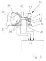
- FIG. 2 shows a top view of an extractor 21 according to FIG Figure 1, in which the glassware is only hinted at.
- a riser 27 is formed in one piece.
- a light barrier arrangement is by means of a holding device 41 32 arranged so that a transmitter element 33 and a Receiver element 34 face each other and through the Riser 27 are separated from each other.
- the holding device 41 is with an adjusting screw 44 on a parallel to Riser 27 arranged guide rail 42 movable attached.
- the distillation vessel 22 is above one Heating device 30 arranged.
- Another separate heating device 37 is between the top of the still 22 and the extraction vessel 24.
- Temperature sensors 38 measure the temperatures of the two Heaters 30 and 37. Those from the receiver element 34 the light barrier arrangement 32 and from the temperature sensors 38 outgoing signals are from the control device 40 evaluated to control valve 1.
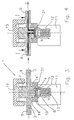
- FIG. 3 shows a cross section through a lifting armature solenoid valve 1, which is used to close and open the return line 26 serves.
- the valve 1 consists essentially of a homogeneous valve body 7 made of glass, for example made of borosilicate glass.
- the valve body 7 is approximately cylindrical and in one piece with nozzles 8 and 9 for supply line 2 and for the derivative 3 is formed.
- a conical mouth 17 integrally formed, which is surrounded by a circumferential groove 18.
- the mouth 17 simultaneously forms the valve seat 5 ( Figure 3) and it is the end of a central bore 19 for the Supply. Derivation takes place from the circumferential groove 18 through a bore 20.
- the valve body 17 is in one pot-shaped housing 10 held, the slots 14, 14 ' for the implementation of the nozzle 8 and 9 ( Figure 5).
- In the upper area is the housing with an external thread provided, on which a cap 15 with an internal thread can be screwed on.
- the closure cap 15 presses the valve body 7 against the bottom 31 in the housing 10.
- the closure cap 15 also as a bayonet lock, toggle lock or the like be trained.
- valve body 7 and the housing 20 together limit one Valve chamber 4, in which a membrane 6 is preferably made of a elastic material is held. The edge area this membrane is clamped and serves at the same time as a seal to the outside.
- a lifting anchor 12 is connected to the membrane 6 by an opening in the bottom 31 and by means of a compression spring 13 in the direction of arrow a biased against the valve seat. When the coil is de-energized thus pressing the membrane against the valve seat and that Valve is closed.
- Figure 4 shows the valve in the open position.
- the below Current set coil pulls the lifting armature 12 against the force the compression spring 13 in the direction of arrow b, the membrane 6 is lifted off the valve seat 5.
- the lead 2 is short-circuited with the lead 3 and there is a flow in the direction of arrow c.
- the two nozzles 8 and 9 are preferably directly in the Return line 26 melted down.
Landscapes
- Engineering & Computer Science (AREA)
- General Engineering & Computer Science (AREA)
- Mechanical Engineering (AREA)
- Physics & Mathematics (AREA)
- Electromagnetism (AREA)
- Chemical & Material Sciences (AREA)
- Chemical Kinetics & Catalysis (AREA)
- Extraction Or Liquid Replacement (AREA)
- Investigating Or Analyzing Materials Using Thermal Means (AREA)
Claims (16)
- Extracteur (21) pour l'extraction solide-liquide du type Soxhlet, comprenant un récipient de distillation (22) apte à être chauffé, un récipient d'extraction (24) disposé au-dessus de celui-ci pour recevoir le matériau à soumettre à l'extraction et l'extrait, et un réfrigérant (23) pour condenser l'agent d'extraction, étant précisé que pour ramener périodiquement l'extrait du récipient d'extraction (24) dans le récipient de distillation (22) lorsqu'un niveau (39) prédéfini est atteint, on prévoit une conduite de recyclage (26) qui part de la zone du fond du récipient d'extraction (24) et qui débouche dans le récipient de distillation (22), caractérisé en ce que la conduite de recyclage (26) présente une inclinaison sur toute sa longueur, du récipient d'extraction (24) au récipient de distillation (22), et en ce que la conduite de recyclage comporte, pour l'ouvrir et la fermer, une soupape (1).
- Extracteur selon la revendication 1, caractérisé en ce que la soupape (1) est une électrovanne.
- Extracteur selon la revendication 1 ou 2, dans lequel le récipient d'extraction (24) et la conduite de recyclage (26) sont conçus comme un ensemble en verre d'une seule pièce, caractérisé en ce que la soupape (1) comporte des tubulures de raccordement (8, 9) qui sont incorporées directement dans la conduite de recyclage (26).
- Extracteur selon l'une des revendications 1 à 3, caractérisé en ce que la soupape (1) comporte au moins une conduite d'amenée (2) et au moins une conduite d'évacuation (3) qui communiquent avec une chambre de soupape (4) dans laquelle est disposé au moins un siège de soupape (5), en ce que la soupape comporte au moins un élément de fermeture (6) qui coopère de manière étanche avec le siège de soupape et qui est apte à être activé à partir du côté extérieur de la chambre de soupape (4), en ce que la chambre de soupape (4) est limitée partiellement par un corps de soupape homogène (7) en verre sur lequel le siège de soupape (5) est formé d'une seule pièce et qui comporte des tubulures respectives (8, 9) pour la conduite d'amenée (2) et la conduite d'évacuation (3), et en ce que le corps de soupape (7) est retenu de façon amovible dans une enveloppe (10) qui entoure le reste de la chambre de soupape.
- Extracteur selon la revendication 4, caractérisé en ce que l'élément de fermeture comporte une membrane (6) dont la zone du bord est serrée fermement et de façon étanche entre le corps de soupape (7) et l'enveloppe (10).
- Extracteur selon la revendication 4 ou 5, caractérisé en ce que le corps de soupape (7) est à peu près cylindrique et en ce que l'enveloppe (10) a à peu près la forme d'un pot et présente des fentes latérales (14, 14') par lesquelles les tubulures (8, 9) sortent de l'enveloppe, le corps de soupape (7) pouvant être fixé à l'aide d'un couvercle (15) apte à être posé sur l'enveloppe.
- Extracteur selon les revendications 5 et 6, caractérisé en ce que le siège de soupape (5) est conçu comme une ouverture conique (17) sur un côté frontal (16) du corps de soupape (7).
- Extracteur selon la revendication 7, caractérisé en ce que l'ouverture conique (17) est entourée par une rainure circulaire (18) dans laquelle débouche un perçage (20) prévu pour la conduite d'évacuation (3).
- Extracteur selon l'une des revendications 1 à 8, caractérisé en ce que des moyens (28) pour déterminer le niveau de liquide (39) sont disposés sur le récipient d'extraction (24), et en ce que la soupape (1) est apte à être commandée par l'intermédiaire de ces moyens en présence d'un niveau prédéfini.
- Extracteur selon la revendication 9, caractérisé en ce qu'il est prévu, a l'extérieur du récipient d'extraction (24), une conduite montante (27) qui communique avec celui-ci, et en ce que les moyens (28) sont disposés sur la conduite montante.
- Extracteur selon la revendication 10, caractérisé en ce que les moyens (28) comportent un dispositif de cellule photo-électrique (32) formé d'un élément émetteur (33) et d'un élément récepteur (34) qui sont disposés sur la conduite montante (27) de telle sorte que le rayon lumineux traverse la conduite montante (27).
- Extracteur selon la revendication 11, caractérisé en ce que le dispositif de cellule photo-électrique (32) est disposé, réglable en hauteur, sur la conduite montante (27).
- Extracteur selon l'une des revendications 10 à 12, caractérisé en ce que la conduite montante (27), au niveau de son extrémité inférieure (35), débouche directement, au-dessus de la soupape (1), dans la conduite de recyclage (26).
- Extracteur selon l'une des revendications 1 à 13, caractérisé en ce que le récipient de distillation (22) comporte un raccordement de gaz inerte (36).
- Extracteur selon l'une des revendications 1 à 14, caractérisé en ce que le récipient d'extraction (24) comporte un dispositif de chauffage séparé (37).
- Extracteur selon l'une des revendications 1 à 15, caractérisé en ce qu'un capteur de température (38) est disposé sur le récipient d'extraction (24) et/ou sur le récipient de distillation (22), et en ce que la soupape (1) est apte à être commandée par l'intermédiaire de la température détectée.
Priority Applications (5)
| Application Number | Priority Date | Filing Date | Title |
|---|---|---|---|
| DE59503267T DE59503267D1 (de) | 1995-06-08 | 1995-06-08 | Extraktor für die Fest-Flüssig-Extraktion nach Soxhlet |
| EP95810380A EP0747103B1 (fr) | 1995-06-08 | 1995-06-08 | Extracteur soxhlet pour extraction solide/liquide |
| AT95810380T ATE169836T1 (de) | 1995-06-08 | 1995-06-08 | Extraktor für die fest-flüssig-extraktion nach soxhlet |
| JP13350096A JP4093605B2 (ja) | 1995-06-08 | 1996-05-28 | 固液抽出用ソックスレー抽出器 |
| US08/660,401 US5776317A (en) | 1995-06-08 | 1996-06-07 | Extractor for soxhlet solid-liquid extraction |
Applications Claiming Priority (1)
| Application Number | Priority Date | Filing Date | Title |
|---|---|---|---|
| EP95810380A EP0747103B1 (fr) | 1995-06-08 | 1995-06-08 | Extracteur soxhlet pour extraction solide/liquide |
Publications (2)
| Publication Number | Publication Date |
|---|---|
| EP0747103A1 EP0747103A1 (fr) | 1996-12-11 |
| EP0747103B1 true EP0747103B1 (fr) | 1998-08-19 |
Family
ID=8221752
Family Applications (1)
| Application Number | Title | Priority Date | Filing Date |
|---|---|---|---|
| EP95810380A Expired - Lifetime EP0747103B1 (fr) | 1995-06-08 | 1995-06-08 | Extracteur soxhlet pour extraction solide/liquide |
Country Status (5)
| Country | Link |
|---|---|
| US (1) | US5776317A (fr) |
| EP (1) | EP0747103B1 (fr) |
| JP (1) | JP4093605B2 (fr) |
| AT (1) | ATE169836T1 (fr) |
| DE (1) | DE59503267D1 (fr) |
Families Citing this family (12)
| Publication number | Priority date | Publication date | Assignee | Title |
|---|---|---|---|---|
| SE503761C2 (sv) * | 1995-06-16 | 1996-08-26 | Tecator Ab | Anordning för lösningsmedelsextraktion |
| US6790318B2 (en) | 2002-09-27 | 2004-09-14 | Bausch & Lomb Incorporated | Method of purification of polymeric medical device materials using continuous soxhlet extraction |
| KR100556354B1 (ko) * | 2002-09-30 | 2006-03-03 | 엘지전자 주식회사 | 유기물 정제 장치 |
| US20050203305A1 (en) * | 2004-03-11 | 2005-09-15 | Britt Michael L. | Oil extraction system |
| CN100446832C (zh) * | 2006-01-25 | 2008-12-31 | 中国科学院大连化学物理研究所 | 一种用于溶剂萃取的耐高温高压池 |
| KR100817536B1 (ko) * | 2007-10-31 | 2008-03-27 | (주)제네마인 | 상향추출 및 하향추출이 가능한 고성능 추출장치 |
| JP5794520B2 (ja) * | 2011-03-29 | 2015-10-14 | 地方独立行政法人山口県産業技術センター | ポリオレフィンを主成分として含む溶融混練した複合プラスチックの分析方法 |
| ITTV20120086A1 (it) * | 2012-05-16 | 2013-11-17 | Stefano Ruffini | Estrattore |
| US9259666B1 (en) | 2013-01-08 | 2016-02-16 | Tulio Chavez-Gil | Compact extractor/separator apparatus for solid/liquid/gel sample |
| ITRM20130127A1 (it) * | 2013-03-01 | 2014-09-02 | Univ Palermo | Dispositivo per estrarre e purificare analiti da una matrice. |
| DE102015116392A1 (de) * | 2015-09-28 | 2017-03-30 | Endress+Hauser Conducta Gmbh+Co. Kg | Vorrichtung zum Dosieren einer Flüssigkeit |
| CN111729345B (zh) * | 2020-06-19 | 2023-07-14 | 云南中烟工业有限责任公司 | 一种可自动停止的索氏提取装置及其提取树苔香气成分的方法 |
Family Cites Families (7)
| Publication number | Priority date | Publication date | Assignee | Title |
|---|---|---|---|---|
| DE1070894B (fr) * | 1959-12-10 | |||
| US2095056A (en) * | 1934-05-11 | 1937-10-05 | W H Curtin & Co Inc | Apparatus for evaluating oil sands |
| GB843094A (en) * | 1955-09-12 | 1960-08-04 | Harry Lee | Improvements in or relating to valves for fluids |
| FR2257054A1 (en) * | 1974-01-03 | 1975-08-01 | Relle Marcel | Valve for gas detonator on bird scarer - has sprung operating piston holding diaphragm against seat |
| FR2570956B1 (fr) * | 1984-09-28 | 1989-07-28 | Union Fabricants Aliments Comp | Procede et dispositif permettant de separer deux corps par dissolution |
| US5017500A (en) * | 1988-10-11 | 1991-05-21 | C. Gerhardt Fabrik & Lager Chemischer Apparate Gmbh & Co K.G. | Fat extraction process and apparatus |
| AT396622B (de) * | 1990-02-19 | 1993-10-25 | Avl Verbrennungskraft Messtech | Elektromagnetisch betätigbares ventil |
-
1995
- 1995-06-08 DE DE59503267T patent/DE59503267D1/de not_active Expired - Lifetime
- 1995-06-08 AT AT95810380T patent/ATE169836T1/de not_active IP Right Cessation
- 1995-06-08 EP EP95810380A patent/EP0747103B1/fr not_active Expired - Lifetime
-
1996
- 1996-05-28 JP JP13350096A patent/JP4093605B2/ja not_active Expired - Fee Related
- 1996-06-07 US US08/660,401 patent/US5776317A/en not_active Expired - Lifetime
Also Published As
| Publication number | Publication date |
|---|---|
| US5776317A (en) | 1998-07-07 |
| EP0747103A1 (fr) | 1996-12-11 |
| DE59503267D1 (de) | 1998-09-24 |
| ATE169836T1 (de) | 1998-09-15 |
| JPH08332303A (ja) | 1996-12-17 |
| JP4093605B2 (ja) | 2008-06-04 |
Similar Documents
| Publication | Publication Date | Title |
|---|---|---|
| EP0747103A1 (fr) | Extracteur soxhlet pour extraction slide/liquide | |
| DE3529956C2 (fr) | ||
| DE102012004845B4 (de) | Milchaufschäumer | |
| EP0081826B1 (fr) | Dispositif pour purger des condensats et similaires hors de systèmes sous pression | |
| DE2429731C2 (de) | Tropfvorrichtung für Laborflüssigkeiten | |
| DE3417696A1 (de) | Vorrichtung zum volumetrischen abmessen und abfuellen von fluessigkeitsmengen | |
| DE1300622B (de) | Selbsttaetige Vorrichtung zum Ablassen von Fluessigkeiten aus Druckgasanlagen | |
| DE4303645C2 (de) | Vorrichtung zur Bereitstellung befeuchteten Atemgases | |
| DE1055764B (de) | Vorrichtung zum Giessen von Metallkoerpern, insbesondere Metallplatten | |
| DE4409877A1 (de) | Vorrichtung zum Aufbereiten und/oder Extrahieren von Proben mittels eines verdampfungsfähigen Mittels bei erhöhter Temperatur | |
| DE469847C (de) | Kaffeemaschine | |
| DE4427846A1 (de) | Regeleinrichtung für die Temperatur des aus einer Wasserleitung entnommenen Wassers | |
| DE4301343A1 (de) | Verfahren zur Lösungsmittel-Extraktion und Extraktionseinheit dafür sowie Reihengerät aus derartigen Extraktionseinheiten, insbesondere mit Lösungsmittelrückgewinnung | |
| EP0361068B1 (fr) | Dispositif pour séparer des composants à l'état de vapeur d'un courant gazeux | |
| DE814259C (de) | Selbsttaetig arbeitende Fuellvorrichtung fuer Behaelter | |
| DE3804893A1 (de) | Vorrichtung zur ueberpruefung der von einem dispenser abgegebenen fluessigkeitsmenge | |
| EP1985347A1 (fr) | Evaporateur | |
| DE3918077C2 (fr) | ||
| DE3029503C2 (de) | Dosiervorrichtung für Flüssigkeiten | |
| DE2735284C2 (de) | Einrichtung zur Ableitung von Kondensat aus geschlossenen und mit einer Dampfzuleitung versehenen Härtekesseln für die Kalksandsteinfabrikation | |
| DE2233661C3 (de) | Luftbefeuchter für Saunaräume | |
| CH436223A (de) | Gerät zum Ausscheiden und Abführen von Flüssigkeiten aus einem gasförmigen Druckmedium | |
| AT111724B (de) | Drosselvorrichtung und -steuerung für Flüssigkeiten. | |
| EP0206012A1 (fr) | Compteur à fluide ou débitmètre | |
| CH251092A (de) | Kaffeemaschine. |
Legal Events
| Date | Code | Title | Description |
|---|---|---|---|
| PUAI | Public reference made under article 153(3) epc to a published international application that has entered the european phase |
Free format text: ORIGINAL CODE: 0009012 |
|
| AK | Designated contracting states |
Kind code of ref document: A1 Designated state(s): AT BE CH DE DK ES FR GB GR IE IT LI LU MC NL PT SE |
|
| 17P | Request for examination filed |
Effective date: 19970510 |
|
| GRAG | Despatch of communication of intention to grant |
Free format text: ORIGINAL CODE: EPIDOS AGRA |
|
| 17Q | First examination report despatched |
Effective date: 19971217 |
|
| GRAG | Despatch of communication of intention to grant |
Free format text: ORIGINAL CODE: EPIDOS AGRA |
|
| GRAH | Despatch of communication of intention to grant a patent |
Free format text: ORIGINAL CODE: EPIDOS IGRA |
|
| GRAH | Despatch of communication of intention to grant a patent |
Free format text: ORIGINAL CODE: EPIDOS IGRA |
|
| GRAA | (expected) grant |
Free format text: ORIGINAL CODE: 0009210 |
|
| AK | Designated contracting states |
Kind code of ref document: B1 Designated state(s): AT BE CH DE DK ES FR GB GR IE IT LI LU MC NL PT SE |
|
| PG25 | Lapsed in a contracting state [announced via postgrant information from national office to epo] |
Ref country code: NL Free format text: LAPSE BECAUSE OF FAILURE TO SUBMIT A TRANSLATION OF THE DESCRIPTION OR TO PAY THE FEE WITHIN THE PRESCRIBED TIME-LIMIT Effective date: 19980819 Ref country code: IT Free format text: LAPSE BECAUSE OF FAILURE TO SUBMIT A TRANSLATION OF THE DESCRIPTION OR TO PAY THE FEE WITHIN THE PRE;WARNING: LAPSES OF ITALIAN PATENTS WITH EFFECTIVE DATE BEFORE 2007 MAY HAVE OCCURRED AT ANY TIME BEFORE 2007. THE CORRECT EFFECTIVE DATE MAY BE DIFFERENT FROM THE ONE RECORDED.SCRIBED TIME-LIMIT Effective date: 19980819 Ref country code: GR Free format text: LAPSE BECAUSE OF NON-PAYMENT OF DUE FEES Effective date: 19980819 Ref country code: ES Free format text: THE PATENT HAS BEEN ANNULLED BY A DECISION OF A NATIONAL AUTHORITY Effective date: 19980819 |
|
| REF | Corresponds to: |
Ref document number: 169836 Country of ref document: AT Date of ref document: 19980915 Kind code of ref document: T |
|
| REG | Reference to a national code |
Ref country code: CH Ref legal event code: EP |
|
| REG | Reference to a national code |
Ref country code: CH Ref legal event code: NV Representative=s name: HEPP, WENGER & RYFFEL AG |
|
| REF | Corresponds to: |
Ref document number: 59503267 Country of ref document: DE Date of ref document: 19980924 |
|
| REG | Reference to a national code |
Ref country code: IE Ref legal event code: FG4D Free format text: GERMAN |
|
| PG25 | Lapsed in a contracting state [announced via postgrant information from national office to epo] |
Ref country code: SE Free format text: LAPSE BECAUSE OF FAILURE TO SUBMIT A TRANSLATION OF THE DESCRIPTION OR TO PAY THE FEE WITHIN THE PRESCRIBED TIME-LIMIT Effective date: 19981119 Ref country code: PT Free format text: LAPSE BECAUSE OF FAILURE TO SUBMIT A TRANSLATION OF THE DESCRIPTION OR TO PAY THE FEE WITHIN THE PRESCRIBED TIME-LIMIT Effective date: 19981119 Ref country code: DK Free format text: LAPSE BECAUSE OF FAILURE TO SUBMIT A TRANSLATION OF THE DESCRIPTION OR TO PAY THE FEE WITHIN THE PRESCRIBED TIME-LIMIT Effective date: 19981119 |
|
| ET | Fr: translation filed | ||
| GBT | Gb: translation of ep patent filed (gb section 77(6)(a)/1977) |
Effective date: 19981110 |
|
| NLV1 | Nl: lapsed or annulled due to failure to fulfill the requirements of art. 29p and 29m of the patents act | ||
| PG25 | Lapsed in a contracting state [announced via postgrant information from national office to epo] |
Ref country code: IE Free format text: LAPSE BECAUSE OF NON-PAYMENT OF DUE FEES Effective date: 19990504 |
|
| PG25 | Lapsed in a contracting state [announced via postgrant information from national office to epo] |
Ref country code: LU Free format text: LAPSE BECAUSE OF NON-PAYMENT OF DUE FEES Effective date: 19990608 Ref country code: AT Free format text: LAPSE BECAUSE OF NON-PAYMENT OF DUE FEES Effective date: 19990608 |
|
| PLBE | No opposition filed within time limit |
Free format text: ORIGINAL CODE: 0009261 |
|
| STAA | Information on the status of an ep patent application or granted ep patent |
Free format text: STATUS: NO OPPOSITION FILED WITHIN TIME LIMIT |
|
| PG25 | Lapsed in a contracting state [announced via postgrant information from national office to epo] |
Ref country code: BE Free format text: LAPSE BECAUSE OF NON-PAYMENT OF DUE FEES Effective date: 19990630 |
|
| REG | Reference to a national code |
Ref country code: IE Ref legal event code: FD4D |
|
| 26N | No opposition filed | ||
| BERE | Be: lapsed |
Owner name: BUCHI LABORTECHNIK A.G. Effective date: 19990630 |
|
| PG25 | Lapsed in a contracting state [announced via postgrant information from national office to epo] |
Ref country code: MC Free format text: LAPSE BECAUSE OF NON-PAYMENT OF DUE FEES Effective date: 19991231 |
|
| REG | Reference to a national code |
Ref country code: GB Ref legal event code: IF02 |
|
| PGFP | Annual fee paid to national office [announced via postgrant information from national office to epo] |
Ref country code: GB Payment date: 20140604 Year of fee payment: 20 |
|
| PGFP | Annual fee paid to national office [announced via postgrant information from national office to epo] |
Ref country code: DE Payment date: 20140603 Year of fee payment: 20 |
|
| PGFP | Annual fee paid to national office [announced via postgrant information from national office to epo] |
Ref country code: CH Payment date: 20140828 Year of fee payment: 20 |
|
| PGFP | Annual fee paid to national office [announced via postgrant information from national office to epo] |
Ref country code: FR Payment date: 20140609 Year of fee payment: 20 |
|
| REG | Reference to a national code |
Ref country code: DE Ref legal event code: R071 Ref document number: 59503267 Country of ref document: DE |
|
| REG | Reference to a national code |
Ref country code: CH Ref legal event code: PL |
|
| REG | Reference to a national code |
Ref country code: GB Ref legal event code: PE20 Expiry date: 20150607 |
|
| PG25 | Lapsed in a contracting state [announced via postgrant information from national office to epo] |
Ref country code: GB Free format text: LAPSE BECAUSE OF EXPIRATION OF PROTECTION Effective date: 20150607 |