EP0753792A1 - Système de transfert de film - Google Patents
Système de transfert de film Download PDFInfo
- Publication number
- EP0753792A1 EP0753792A1 EP96305014A EP96305014A EP0753792A1 EP 0753792 A1 EP0753792 A1 EP 0753792A1 EP 96305014 A EP96305014 A EP 96305014A EP 96305014 A EP96305014 A EP 96305014A EP 0753792 A1 EP0753792 A1 EP 0753792A1
- Authority
- EP
- European Patent Office
- Prior art keywords
- film
- spool
- cartridge
- film transfer
- take
- Prior art date
- Legal status (The legal status is an assumption and is not a legal conclusion. Google has not performed a legal analysis and makes no representation as to the accuracy of the status listed.)
- Granted
Links
Images


Classifications
-
- G—PHYSICS
- G03—PHOTOGRAPHY; CINEMATOGRAPHY; ANALOGOUS TECHNIQUES USING WAVES OTHER THAN OPTICAL WAVES; ELECTROGRAPHY; HOLOGRAPHY
- G03D—APPARATUS FOR PROCESSING EXPOSED PHOTOGRAPHIC MATERIALS; ACCESSORIES THEREFOR
- G03D3/00—Liquid processing apparatus involving immersion; Washing apparatus involving immersion
- G03D3/16—Treating exposed material in original holder
-
- G—PHYSICS
- G03—PHOTOGRAPHY; CINEMATOGRAPHY; ANALOGOUS TECHNIQUES USING WAVES OTHER THAN OPTICAL WAVES; ELECTROGRAPHY; HOLOGRAPHY
- G03B—APPARATUS OR ARRANGEMENTS FOR TAKING PHOTOGRAPHS OR FOR PROJECTING OR VIEWING THEM; APPARATUS OR ARRANGEMENTS EMPLOYING ANALOGOUS TECHNIQUES USING WAVES OTHER THAN OPTICAL WAVES; ACCESSORIES THEREFOR
- G03B27/00—Photographic printing apparatus
- G03B27/32—Projection printing apparatus, e.g. enlarger, copying camera
- G03B27/52—Details
- G03B27/62—Holders for the original
- G03B27/6271—Holders for the original in enlargers
- G03B27/6285—Handling strips
Definitions
- the present invention relates to an improvement of a film transfer apparatus for subjecting a film to a desired process at an exposure station.
- Film transfer apparatuses are known in which a film drawn out from a cartridge is temporarily rewound on a take-up member so that it can be subjected repeatedly to printing processes with minimum risks of damage or injury.
- Each conventional film transfer apparatus has two drive motors for driving a spool rotating shaft of the cartridge and the take-up member respectively, thus increasing the arrangement difficulty and the dimensions. It often happens that a film is jammed and damaged during its unwinding and rewinding operations.
- a film transfer apparatus has a cartridge set station, a spool rotating mechanism for rotating a spool in a cartridge, a process station for subjecting a film supplied from the cartridge to a desired process, a take-up means for taking up the film released from the process station for storage, a take-up means rotating mechanism for driving the take-up means, a film transfer path provide with a film transfer mechanism, and a drive motor.
- the film transfer apparatus is characterized in that the spool and take-up means rotating mechanisms are provided with frictions which prevent loading of an excessive force to the film, and in that the drive motor is connected to the film transfer mechanism which in turn is linked to the spool and take-up means rotating mechanisms so that the rotation of the drive motor is transmitted through the film transfer mechanism to the spool and take-up rotating mechanisms.
- the film transfer apparatus may be arranged in which the spool rotating mechanism has a clutch for disconnecting the transmission of power to the spool in the cartridge upon the leading end of the film from the cartridge reaching the film transfer mechanism.
- Another film transfer apparatus has a cartridge set station provided at one end of a film transfer path and a film process station provided at an intermediate location of the film transfer path for drawing a film from a cartridge loaded to the cartridge set station, advancing it by the action of a film transfer means to the film process station where it is scanned or exposed for printing, and returning it to the cartridge.
- the film transfer apparatus further comprises a detecting means for detecting removal of the trailing end of the film from the cartridge, a film drawing means responsive to a detection signal of the detecting means for drawing out from the cartridge the film which has been removed from its spool, and a film discharging means for unloading from the film transfer path the film which has been drown from the cartridge.
- the film transfer apparatus may be arranged in which the film transfer means comprises a film transfer mechanism linked to a drive motor, and the detecting means comprises a rotary detection disk and a rotation sensor, the rotary detection disk arranged to stop its rotating motion when the trailing end of the film of which final frame has been subjected to a desired process is not separated from the spool or to keep rotating due to a driving force of the film transfer mechanism when the trailing end is separated from the spool, the rotation sensor arranged to detect the continuous rotation of the rotary detection disk after the final frame has been subjected to the process.
- the film transfer apparatus may further comprise an idling means for canceling the driving force of the film transfer mechanism to prevent exertion of an excessive load on to the film when the trailing end of the film is not separated from the spool.
- Figs. 1 to 5 illustrate a first embodiment of a film transfer apparatus according to the present invention.
- Fig. 1 is a plan view of the film transfer apparatus.
- the film transfer apparatus includes, as shown, a process station 2 provided across a film transfer path 1 for subjecting the film F to a process, and a cartridge set station 3 and a pulley 4 (a rewinder) disposed on both ends of the film transfer path 1 for feeding, taking up, and holding the film F which has been processed at the processing station 2.
- the film transfer mechanism 5 comprises three, first, second, and third, pairs of transfer roller assemblies 51, 52, and 53 which consist mainly of drive rollers 51a, 52a, 53a and pinch rollers 51b, 52b, 53b respectively.
- the first, second, and third drive rollers 51a, 52a, and 53a are mounted on drive shafts 51c, 52c, and 53c respectively which also hold three pulleys 51d, 52d, and 53d.
- the pulleys 51d, 52d, and 53d are linked by a drive belt 54 to a drive pulley of a drive motor 8 which will be described later.
- S1 is a loading sensor which comprises a detector element and a photosensitive element and is mounted between the first and second transfer roller assemblies 51 and 52.
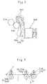
- a spool rotating mechanism 6 is provided for rotating the spool (not shown) of a cartridge C loaded on the cartridge set station 3 and comprises a drive shaft 61, two spool rotating shafts 62 and 62A, a friction 63, and a clutch 64.
- the rotation of the drive shaft 61 is transmitted through a set of gears 61a, 61b and 61c, and a clutch gear 64C, described later, to the spool rotating mechanism 62.
- the clutch 64 controls the transmission of the rotation from the drive shaft 61 to the spool rotating shaft 62.
- the clutch 64 comprises a clutch lever 64A, a solenoid 64B, and a clutch gear 64C.
- the clutch lever 64A is rotata mounted on the drive shaft 61.
- a rotary detection disk 66 has a notch or aperture (not shown) provided in the outer edge thereof and is mounted on the drive shaft 61.
- S2 Denoted by S2 is a rotation sensor which has a detector element and a photosensitive element for counting the number of rotations of the rotary detection disk 66 through detecting the passing of the notch or aperture.
- the sensor S2 starts counting the number of rotations upon the leading end of the film F departing from the first transfer roller assembly 51 of the film transfer mechanism 5.
- the solenoid 64B releases the clutch lever 64A to prevent over-running of the film F.
- the axle of the friction 63 is linked by a coupling 65 to the drive shaft 51c of the first drive roller assembly 51a of the film transfer mechanism 5.
- the friction 63 is also coupled to the drive shaft 61 by a drive belt 67 mounted between two pulleys 61A and 63a of the friction 63 and drive shaft 61 respectively.
- the friction 63 of the spool rotating mechanism 6 may be a combination of an outer body and a drive shaft which are closely joined to each other by a frictional material.
- the friction 63 absorbs a difference between the feeding of the film F by the drive roller assemblies of the film transfer mechanism 5 and the rewinding of the film F by the spool rotating shaft 62. In action, the friction 63 allows slipping of the outer body on its rotating drive shaft to prevent the film F from being overloaded with more than a critical value.
- the friction 63 is not limited to the prescribed construction and will be arranged in any other appropriate form which can eliminate the difference of movement.
- the friction 63 is in the form of a torque limiter.
- a take-up rotating mechanism 7 is provided for rotating the take-up pulley 4.
- the take-up rotating mechanism 7 comprises a friction 71 mounted on a shaft of the take-up pulley 4 and a take-up gear 71a.
- the take-up gear 71a is mounted on a drive shaft 71A to which a pulley 71B is also secured.
- a drive belt 72 is mounted between the pulley 71B and a pulley 53e mounted on the drive shaft 53c of the third drive roller assembly 53a.
- the friction 71 of the take-up rotating mechanism 7 may be a rotary unit comprising an outer body and a drive shaft.
- the outer body is closely joined by a frictional material to the drive shaft.
- the friction 71 absorbs a difference between the feeding of the film F by the drive roller assemblies of the film transfer mechanism 5 and the taking up of the film F by the take-up pulley 4. More specifically, the friction 71 allows slipping of the outer body on its rotating drive shaft to prevent the film F from being overloaded with more than a critical value.
- the friction 71 is not limited to the prescribed construction and will be arranged in any other appropriate form which can eliminate the difference of movement.
- the friction 71 is in the form of an oil damper.
- the drive motor 8 is provided for forwarding the film F one frame at a time and reversing it in continuous motion.
- the drive motor 8 has a drive shaft 81 on which the drive pulley 82 is mounted.
- the process station 2 comprises an exposure stage 2A and a scanning stage. At the exposure stage 2A, a frame of the film F paused in a print gate 21A is projected by light source on to a sheet of printing paper (not shown).
- the film F can smoothly be unwound and rewound on the cartridge C or the take-up pulley 4 without being jammed or injured.
- Figs. 6 to 10 illustrate a second embodiment of the film transfer apparatus according to the present invention.
- Fig. 6 is a plan view of the film transfer apparatus.
- the film transfer apparatus of the second embodiment comprises a process station 2 provided across a film path 1 for subjecting the film F to a desired process, and a cartridge set station 3 and a take-up pulley 4 (a rewinder) for rewinding the film F processed at the process station 2.
- the process station 2 comprises an exposure stage and a scanning stage. At the exposure stage, the film F is exposed through a print gate 21A to an intensity of exposure light for printing a frame picture on a sheet of printing paper (not shown).
- the scanning stage includes a magnetic head (not shown) for reading and writing data on magnetic recording tracks of the film F.
- Denoted by 8 is a drive motor (a film transfer motor) for advancing the film F one frame at a time in its forward rotation mode and reversing it continuously in its backward rotation mode.
- the drive motor 8 has a drive shaft 81 on which a drive pulley 82 is mounted.
- a film transfer mechanism 5 is provided along the transfer path 1 and comprises two, first and second, transfer roller assemblies 51 and 52.
- the transfer roller assemblies 51 and 52 include drive rollers 51a and 52a, and press roller 51b and 52b respectively (Figs. 6 and 7).
- the first drive roller 51a is mounted on a drive shaft 51c to which two pulleys 51d and 51e are fitted.
- the second drive roller 52a is mounted on a drive shaft 52c to which a pulley 52d is fitted.
- the take-up rotating mechanism 7 comprises a friction 71 mounted on a pulley shaft of the take-up pulley 4, and a take-up drive gear 71a.
- the take-up drive gear 71 is mounted on a drive shaft 71A to which a pulley 71B is fitted.
- a friction shaft 63 is provided on which frictions 63A and 63B and a pulley 631 are mounted.
- a drive belt B1 is mounted between the pulley 631 and the drive pulley 82 of the drive motor 8. Also, shown is a guide pulley G1.
- a drive belt B2 is mounted to run along the friction 63B, the pulley 71B of the take-up rotating mechanism 7, the pulley 51d of the first drive shaft 51c, and the pulley 52d of the second drive shaft 52c in the film transfer mechanism 5.
- guide pulleys G2, G3, and G4 are further provided.
- the rotation of the drive motor 8 is transmitted through the friction 63B to first and second drive shafts 51c, 52c for driving both the transfer roller assemblies 51 and 52.
- S1 is a loading sensor comprising a combination of a detector element and a photosensitive element for detecting the leading end of the film F.
- the loading sensor S1 is mounted between the cartridge set station 3 and the first transfer roller assembly 51.
- a trailing-end detection sensor S3 (a loading sensor) which comprises a combination of a detector element and a photosensitive element for detecting the trailing end of the film F.
- the sensor S3 is mounted between the first transfer roller assembly 51 and the second transfer roller assembly 52, but close to the later.
- a spool rotating mechanism 6 is provided for rotating a spool C2 in a cartridge C loaded to the cartridge set station 3.
- the spool rotating mechanism 6 comprises a drive shaft 61, spool rotating shafts 62 and 62A, and a clutch 64.
- the rotation of the drive shaft 61 is transmitted through a set of gears 61a, 61b, and 61c, and a clutch gear 64C described later to the spool rotating shaft 62.
- the clutch 64 controls the transmission of the rotation from the drive shaft 61 to the spool rotating shaft 62.
- the clutch 64 comprises a clutch lever 64A, a solenoid 64B, and a clutch gear 64C.
- the clutch lever 64A is rotatably mounted on the drive shaft 61.
- a rotary detection disk 66 is mounted on the drive shaft 61 and has an aperture or notch (not shown) provided in the outer edge thereof.
- the passing of the aperture or notch of the rotary detection disk 66 is detected by a rotation sensor S2 for counting the number of rotations.
- the rotation sensor S2 comprises a combination of a detector element and a photosensitive element.
- the rotation sensor S2 starts counting the number of rotations of the rotary detection disk 66 upon the leading end of the film F departing from the first transfer roller assembly 51 of the film transfer mechanism 5.
- the solenoid 64B releases a clutch lever 64A to prevent overrunning of the film F.
- the rotary detection disk 66 When the trailing end of the film F has departed from the spool C1 of the cartridge C, the rotary detection disk 66 remains rotating with the final frame of the film F being processed. The departure of the film F is detected by the rotation sensor S2 which in turn produces and sends a trailing-end departure signal to a driver circuit for continuous motion of the drive motor 8. Upon the film F being rewound up on the take-up pulley 4, its trailing end is detected by the trailing-end detection sensor S3 which thus stops the advancing movement of the film F.
- the drive shaft 61 of the rotary detection disk 66 has a pulley 611 mounted thereon.
- a drive belt B4 is mounted to run along the pulley 611, the friction 63A of the friction drive shaft 63, and the pulley 51e of the first drive shaft 51c in the film transfer mechanism 5. Also, shown is a guide pulley G5.
- the rotation of the drive motor 8 is transmitted through the friction 63A to the first drive shaft 51c and simultaneously, through the friction 63A and clutch 64 to the spool rotating shaft 61.
- the frictions 63A and 63B allow the drive pulley 82 of the drive motor 8 to run idle without transmitting its rotation to the transfer roller assemblies 51 and 52 after the last frame of the film F is subjected to the process.
- the rotary detection disk 66 stops its movement.
- the rotation sensor S2 thus detects the stop action of the rotary detection disk 66 and switches on the solenoid 64B for the clutch 64 to connect the drive shaft 61 in the spool rotating mechanism 6 with the spool rotating shaft 62.
- Each of the frictions 63A and 63B on the friction shaft 63 may be a rotary unit comprising a drive shaft and an outer body.
- the outer body is closely joined to the drive shaft by a frictional material.
- the friction 63B causes the drive pulley 82 of the drive motor 8 to rotate idle thus preventing the film F from being overloaded with an excessive force due to the continuous forwarding action of the transfer roller assemblies 51 and 52 with the final frame having been subjected to the process. More specifically, the outer body of the friction 63B is slipped on the drive shaft 63 for preventing overloading on the film F.
- the frictions 63A and 63B are not limited to the above construction, e.g. a torque limiter, and any other means for eliminating the difference in movement will be applicable.
- the friction 71 namely an oil damper, of the take-up rotating mechanism 7 eliminates the difference of movement between the forwarding distance of the film by the drive rollers of the film transfer mechanism 5 and the rewinding length on the take-up pulley 4. More particularly, the outer body of the friction 71 is slipped on its drive shaft for preventing the film F from being overloaded with an excessive force.
- the friction 71 may has a construction identical to that of the first embodiment.
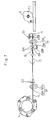
- a movable film guide 10 for guiding the film F along the transfer path 1 and easing removal of the film F from the transfer path 1.
- the movable film guide 10 comprises a guide body 10A and a solenoid 10B.
- the guide body 10A is pivoted in a see-saw form as shown by the two-dot chain line in Fig. 7.
- the solenoid 10B When the solenoid 10B is switched on, its actuator 10C drives the guide body 1 to the location denoted by the two-dot chain line for removal of the film F.
- the solenoid 10B When the solenoid 10B is switched off, its actuator 10C pulls the guide body 10A to the location denoted by the real line for allowing the film F to be advanced along the transfer path 1.
- Denoted by 11 is a stationary film guide.
Landscapes
- Physics & Mathematics (AREA)
- General Physics & Mathematics (AREA)
- Projection-Type Copiers In General (AREA)
- Photographic Developing Apparatuses (AREA)
Applications Claiming Priority (6)
| Application Number | Priority Date | Filing Date | Title |
|---|---|---|---|
| JP174945/95 | 1995-07-11 | ||
| JP17494595 | 1995-07-11 | ||
| JP7174945A JP2833526B2 (ja) | 1995-07-11 | 1995-07-11 | フィルム送り出し・巻き取り装置 |
| JP10788096 | 1996-04-26 | ||
| JP10788096A JP3409577B2 (ja) | 1996-04-26 | 1996-04-26 | フィルム搬送装置 |
| JP107880/96 | 1996-04-26 |
Publications (2)
| Publication Number | Publication Date |
|---|---|
| EP0753792A1 true EP0753792A1 (fr) | 1997-01-15 |
| EP0753792B1 EP0753792B1 (fr) | 2001-12-12 |
Family
ID=26447853
Family Applications (1)
| Application Number | Title | Priority Date | Filing Date |
|---|---|---|---|
| EP96305014A Expired - Lifetime EP0753792B1 (fr) | 1995-07-11 | 1996-07-05 | Système de transfert de film |
Country Status (4)
| Country | Link |
|---|---|
| EP (1) | EP0753792B1 (fr) |
| KR (1) | KR970007481A (fr) |
| CA (1) | CA2180708C (fr) |
| DE (1) | DE69617819T2 (fr) |
Citations (1)
| Publication number | Priority date | Publication date | Assignee | Title |
|---|---|---|---|---|
| US3586430A (en) * | 1968-03-12 | 1971-06-22 | Bell & Howell Co | Film transport apparatus |
Family Cites Families (1)
| Publication number | Priority date | Publication date | Assignee | Title |
|---|---|---|---|---|
| EP0582852B1 (fr) * | 1992-07-15 | 1998-01-07 | Fuji Photo Film Co., Ltd. | Dispositif et méthode de chargement et d'enlèvement de film dans une cassette de film photographique |
-
1996
- 1996-06-17 KR KR1019960021822A patent/KR970007481A/ko not_active Ceased
- 1996-07-05 EP EP96305014A patent/EP0753792B1/fr not_active Expired - Lifetime
- 1996-07-05 DE DE69617819T patent/DE69617819T2/de not_active Expired - Fee Related
- 1996-07-08 CA CA002180708A patent/CA2180708C/fr not_active Expired - Fee Related
Patent Citations (1)
| Publication number | Priority date | Publication date | Assignee | Title |
|---|---|---|---|---|
| US3586430A (en) * | 1968-03-12 | 1971-06-22 | Bell & Howell Co | Film transport apparatus |
Also Published As
| Publication number | Publication date |
|---|---|
| DE69617819T2 (de) | 2002-06-20 |
| EP0753792B1 (fr) | 2001-12-12 |
| CA2180708C (fr) | 2000-02-22 |
| KR970007481A (ko) | 1997-02-21 |
| CA2180708A1 (fr) | 1997-01-12 |
| DE69617819D1 (de) | 2002-01-24 |
Similar Documents
| Publication | Publication Date | Title |
|---|---|---|
| US4527172A (en) | Thermal transfer recording apparatus | |
| JP3454348B2 (ja) | 感光材料の搬送装置 | |
| US6820831B2 (en) | Winding method and device for photo film and photo film carrier | |
| EP0753792B1 (fr) | Système de transfert de film | |
| US5446511A (en) | Original conveying apparatus | |
| JP2833526B2 (ja) | フィルム送り出し・巻き取り装置 | |
| US5721610A (en) | Film image pickup device | |
| EP0762191B1 (fr) | Méthode pour dérouler et enrouler du matériau photosensible | |
| JP3409577B2 (ja) | フィルム搬送装置 | |
| JPH09165126A (ja) | ロール紙給紙装置 | |
| JP2917803B2 (ja) | フィルム搬送装置 | |
| KR100224129B1 (ko) | 필름반송장치 | |
| JP2001354341A (ja) | 蛇行防止装置及びプリンタ装置 | |
| JP3548278B2 (ja) | フィルムキャリア | |
| JP3353569B2 (ja) | フィルム自動搬送装置 | |
| JPH0541534B2 (fr) | ||
| JP3401770B2 (ja) | フイルム搬送装置 | |
| JP3374871B2 (ja) | フイルム搬送方法及び装置 | |
| JP3690521B2 (ja) | フイルム搬送装置 | |
| JPH0141709Y2 (fr) | ||
| JPS63267575A (ja) | 感熱転写記録装置のたるみ取り方法 | |
| JP3560757B2 (ja) | 自動原稿搬送装置 | |
| JPH07109039A (ja) | シート材の分離給送方法及びシート材の分離給送装置 | |
| JPH11242715A (ja) | 情報記録媒体のクリーニング装置 | |
| JPH07114228A (ja) | 原稿搬送装置及び投影装置 |
Legal Events
| Date | Code | Title | Description |
|---|---|---|---|
| PUAI | Public reference made under article 153(3) epc to a published international application that has entered the european phase |
Free format text: ORIGINAL CODE: 0009012 |
|
| 17P | Request for examination filed |
Effective date: 19961015 |
|
| AK | Designated contracting states |
Kind code of ref document: A1 Designated state(s): CH DE FR GB IT LI |
|
| 17Q | First examination report despatched |
Effective date: 20000912 |
|
| GRAG | Despatch of communication of intention to grant |
Free format text: ORIGINAL CODE: EPIDOS AGRA |
|
| GRAG | Despatch of communication of intention to grant |
Free format text: ORIGINAL CODE: EPIDOS AGRA |
|
| GRAH | Despatch of communication of intention to grant a patent |
Free format text: ORIGINAL CODE: EPIDOS IGRA |
|
| GRAH | Despatch of communication of intention to grant a patent |
Free format text: ORIGINAL CODE: EPIDOS IGRA |
|
| GRAA | (expected) grant |
Free format text: ORIGINAL CODE: 0009210 |
|
| AK | Designated contracting states |
Kind code of ref document: B1 Designated state(s): CH DE FR GB IT LI |
|
| PG25 | Lapsed in a contracting state [announced via postgrant information from national office to epo] |
Ref country code: LI Free format text: LAPSE BECAUSE OF FAILURE TO SUBMIT A TRANSLATION OF THE DESCRIPTION OR TO PAY THE FEE WITHIN THE PRESCRIBED TIME-LIMIT Effective date: 20011212 Ref country code: IT Free format text: LAPSE BECAUSE OF FAILURE TO SUBMIT A TRANSLATION OF THE DESCRIPTION OR TO PAY THE FEE WITHIN THE PRE;WARNING: LAPSES OF ITALIAN PATENTS WITH EFFECTIVE DATE BEFORE 2007 MAY HAVE OCCURRED AT ANY TIME BEFORE 2007. THE CORRECT EFFECTIVE DATE MAY BE DIFFERENT FROM THE ONE RECORDED.SCRIBED TIME-LIMIT Effective date: 20011212 Ref country code: CH Free format text: LAPSE BECAUSE OF FAILURE TO SUBMIT A TRANSLATION OF THE DESCRIPTION OR TO PAY THE FEE WITHIN THE PRESCRIBED TIME-LIMIT Effective date: 20011212 |
|
| REG | Reference to a national code |
Ref country code: CH Ref legal event code: EP |
|
| REG | Reference to a national code |
Ref country code: GB Ref legal event code: IF02 |
|
| REF | Corresponds to: |
Ref document number: 69617819 Country of ref document: DE Date of ref document: 20020124 |
|
| ET | Fr: translation filed | ||
| REG | Reference to a national code |
Ref country code: CH Ref legal event code: PL |
|
| PLBE | No opposition filed within time limit |
Free format text: ORIGINAL CODE: 0009261 |
|
| STAA | Information on the status of an ep patent application or granted ep patent |
Free format text: STATUS: NO OPPOSITION FILED WITHIN TIME LIMIT |
|
| 26N | No opposition filed | ||
| PGFP | Annual fee paid to national office [announced via postgrant information from national office to epo] |
Ref country code: GB Payment date: 20040630 Year of fee payment: 9 |
|
| PGFP | Annual fee paid to national office [announced via postgrant information from national office to epo] |
Ref country code: FR Payment date: 20040708 Year of fee payment: 9 |
|
| PG25 | Lapsed in a contracting state [announced via postgrant information from national office to epo] |
Ref country code: GB Free format text: LAPSE BECAUSE OF NON-PAYMENT OF DUE FEES Effective date: 20050705 |
|
| GBPC | Gb: european patent ceased through non-payment of renewal fee |
Effective date: 20050705 |
|
| PG25 | Lapsed in a contracting state [announced via postgrant information from national office to epo] |
Ref country code: FR Free format text: LAPSE BECAUSE OF NON-PAYMENT OF DUE FEES Effective date: 20060331 |
|
| REG | Reference to a national code |
Ref country code: FR Ref legal event code: ST Effective date: 20060331 |
|
| PGFP | Annual fee paid to national office [announced via postgrant information from national office to epo] |
Ref country code: DE Payment date: 20090702 Year of fee payment: 14 |
|
| PG25 | Lapsed in a contracting state [announced via postgrant information from national office to epo] |
Ref country code: DE Free format text: LAPSE BECAUSE OF NON-PAYMENT OF DUE FEES Effective date: 20110201 |
|
| REG | Reference to a national code |
Ref country code: DE Ref legal event code: R119 Ref document number: 69617819 Country of ref document: DE Effective date: 20110201 |