EP0762265A2 - Koordinateneingabevorrichtung und Methode - Google Patents
Koordinateneingabevorrichtung und Methode Download PDFInfo
- Publication number
- EP0762265A2 EP0762265A2 EP96113922A EP96113922A EP0762265A2 EP 0762265 A2 EP0762265 A2 EP 0762265A2 EP 96113922 A EP96113922 A EP 96113922A EP 96113922 A EP96113922 A EP 96113922A EP 0762265 A2 EP0762265 A2 EP 0762265A2
- Authority
- EP
- European Patent Office
- Prior art keywords
- coordinate
- data
- sampling
- input
- output
- Prior art date
- Legal status (The legal status is an assumption and is not a legal conclusion. Google has not performed a legal analysis and makes no representation as to the accuracy of the status listed.)
- Granted
Links
Images



Classifications
-
- G—PHYSICS
- G06—COMPUTING OR CALCULATING; COUNTING
- G06F—ELECTRIC DIGITAL DATA PROCESSING
- G06F3/00—Input arrangements for transferring data to be processed into a form capable of being handled by the computer; Output arrangements for transferring data from processing unit to output unit, e.g. interface arrangements
- G06F3/01—Input arrangements or combined input and output arrangements for interaction between user and computer
- G06F3/048—Interaction techniques based on graphical user interfaces [GUI]
- G06F3/0487—Interaction techniques based on graphical user interfaces [GUI] using specific features provided by the input device, e.g. functions controlled by the rotation of a mouse with dual sensing arrangements, or of the nature of the input device, e.g. tap gestures based on pressure sensed by a digitiser
- G06F3/0488—Interaction techniques based on graphical user interfaces [GUI] using specific features provided by the input device, e.g. functions controlled by the rotation of a mouse with dual sensing arrangements, or of the nature of the input device, e.g. tap gestures based on pressure sensed by a digitiser using a touch-screen or digitiser, e.g. input of commands through traced gestures
-
- G—PHYSICS
- G06—COMPUTING OR CALCULATING; COUNTING
- G06F—ELECTRIC DIGITAL DATA PROCESSING
- G06F3/00—Input arrangements for transferring data to be processed into a form capable of being handled by the computer; Output arrangements for transferring data from processing unit to output unit, e.g. interface arrangements
- G06F3/01—Input arrangements or combined input and output arrangements for interaction between user and computer
- G06F3/048—Interaction techniques based on graphical user interfaces [GUI]
- G06F3/0487—Interaction techniques based on graphical user interfaces [GUI] using specific features provided by the input device, e.g. functions controlled by the rotation of a mouse with dual sensing arrangements, or of the nature of the input device, e.g. tap gestures based on pressure sensed by a digitiser
- G06F3/0488—Interaction techniques based on graphical user interfaces [GUI] using specific features provided by the input device, e.g. functions controlled by the rotation of a mouse with dual sensing arrangements, or of the nature of the input device, e.g. tap gestures based on pressure sensed by a digitiser using a touch-screen or digitiser, e.g. input of commands through traced gestures
- G06F3/04883—Interaction techniques based on graphical user interfaces [GUI] using specific features provided by the input device, e.g. functions controlled by the rotation of a mouse with dual sensing arrangements, or of the nature of the input device, e.g. tap gestures based on pressure sensed by a digitiser using a touch-screen or digitiser, e.g. input of commands through traced gestures for inputting data by handwriting, e.g. gesture or text
-
- G—PHYSICS
- G06—COMPUTING OR CALCULATING; COUNTING
- G06F—ELECTRIC DIGITAL DATA PROCESSING
- G06F3/00—Input arrangements for transferring data to be processed into a form capable of being handled by the computer; Output arrangements for transferring data from processing unit to output unit, e.g. interface arrangements
- G06F3/01—Input arrangements or combined input and output arrangements for interaction between user and computer
- G06F3/03—Arrangements for converting the position or the displacement of a member into a coded form
- G06F3/041—Digitisers, e.g. for touch screens or touch pads, characterised by the transducing means
Definitions
- This invention relates to coordinate input device and method for generating data based on coordinate positions specified by an operator.
- digitizers which are used as sampling devices.
- One of such devices permits handwriting input of the operator using an input appliance such as stylus pen.
- the device of this type provides handwriting computing applications, differently from that using a keyboard, by displaying an input trace to a host computer based on coordinate data from the coordinate input device, or by recognizing strings of input coordinate points as a character.
- the coordinate input device referred herein is configured to transmit, to the host computer, an X-Y coordinate pair indicative of a position of the stylus pen, the X-Y coordinate system using a certain point in the input area of the device as the origin, every predetermined time or when a change in input point becomes large, i.e., when it exceeded a predetermined amount, or in response to a command from the host computer.
- the host computer On receipt of the coordinates, the host computer displays a string of input points by connecting them by a straight line or interpolating curve such as a spline curve or Bezier curve. This provides to the operator a feeling as if he or she wrote the curve with a pen on a paper.
- a straight line or interpolating curve such as a spline curve or Bezier curve.
- information output from typical coordinate input devices generally contains only coordinates indicative of the input position.
- information output from typical coordinate input devices generally contains only coordinates indicative of the input position.
- the coordinate points to be passed are shown and theoretically the passing direction at each point is present inexhaustibly. Since the coordinate information is usually given in the form of a string of points, the host apparatus connects the input coordinate points by a straight line or interpolating curve to display the input trace.
- curve interpolation may be used not to increase the storage capacity.
- One common curve interpolation uses a three-dimensional spline curve.
- an object of the present invention is to provide coordinate input device and method capable of interpolating sampling data more faithful to input data with less input data and in simper computing.
- Another object of the present invention is to provide coordinate input device and method capable of obtaining a trace more faithful to an input trace with less coordinate information and simpler computing.
- Still another object of the present invention is to provide coordinate input device and method capable of adding information indicative of a direction of an input trace at each coordinate point of sampling data.
- the conventional coordinate input device and the host apparatus have been configured to exchange information therebetween such that the coordinate input device transmits, to the host apparatus, all kinds of information mainly containing coordinate information given at a predetermined, constant sampling rate, while the host apparatus uses the transmitted coordinate information for execution of all kinds of processings such as curve interpolation, information transmission, enlarged/reduced display, information storage and graph/character recognition.
- the use of the coordinate information from the coordinate input device to carry out a normal enlarged display processing onto a large-scale display screen consisting of small pixels may produce a trace of the coordinate strings connected by polygonal lines, as shown in Fig. 19, different from the original input curves, even if a user input a Japanese character pronounced "a", with smooth curves using the pen appliance as shown in Fig. 18.
- the host apparatus may execute a curve interpolation processing based on the coordinate information to overcome the above problem.
- a curve interpolation processing based on the coordinate information to overcome the above problem.
- apparently displayed character can be reproduced on the display screen, but other problems arise that processing time for the curve interpolation takes much longer and real-time operativity until displayed after input is impaired.
- a compression technique may be used together depending on final storage or communication protocol.
- the host apparatus is required to temporarily store all the coordinate information from the coordinate input device without fail, therefore, still another problem arises that a trace required for a long input time involves an increasing quantity of information. Likewise, this problem occurs when the host apparatus transfers information to an external device.
- the use of all the coordinate information to execute character or graph recognition in the same manner as aforementioned may be extremely wasteful in a case requiring high-speed operation at the beginning of the recognition processing step such as stroke matching or matching between initial and terminal points. It is therefore desirable to normalize the information size or thin out the coordinate information.
- the coordinate information is too small to execute a final recognition processing step at which further detailed recognition should be done such as similar-character discrimination.
- the coordinate information is either insufficient or wasteful for each individual step in one processing.
- the present invention is also to solve the above problems by a coordinate input device capable of outputting coordinate information from the input coordinate input device to a host apparatus with less information content but as effective coordinate information.
- the conventional input device such as a digitizer is mainly used to input, to the host apparatus, coordinate data corresponding to each coordinate position specified on a coordinate input surface.
- the host apparatus converts the coordinate data to each arithmetic expression representative of a curve so that a graph or graphic character can be plotted or created.
- the created graphic data is then stored or displayed.
- the coordinate input device outputs the coordinate data to a CPU of the host apparatus at a fixed time interval, while the CPU converts the coordinate data into a curve using a Bezier curve technique or B-spline function for displaying or storing the curve.
- the host apparatus since the coordinate data is transmitted from the coordinate input device to the host apparatus at a fixed time interval, a delay is produced in the coordinate data read-in process when the processing steps at the host apparatus are complicated. It is therefore required that the host apparatus sequentially inputs and stores the coordinate data to display the coordinate data input at a fixed time interval by connecting them with a straight line and to display a curve by converting the coordinate data using the Bezier curve technique or the like.
- Such a double display configuration may provide a sense of incongruity to the operator due to a difference between two displayed traces.
- the host apparatus can not read all the coordinate data input at a short time interval while displaying the curve unless the processing speed of the CPU in the host apparatus is extremely high. For this reason, some of coordinate data may be missing within the traced curve when the coordinate data are sequentially input at a high speed and at a short time interval. In this case, although the time interval at which the coordinate data are sequentially input may be extended to avoid the missing coordinate data, this causes a failure in tracing a curve faithful to the graph or character originally drawn or written by the operator.
- the present invention is also made in view of the above further problems and yet another object thereof to provide coordinate input device and method capable of generating data for curve approximation based on coordinates specified by an operator.
- One form of the present invention provides a coordinate input device comprising first sampling means for sampling input data with a predetermined sampling cycle; second sampling means for sampling the input data at least at one moment staggered by a predetermined period from the time when the first sampling means sampled the input data; and output means for supplying output data based on sampling data from the first and second sampling means.
- a coordinate input device includes curve calculation means which starts calculating an approximate curve based on at least four points of coordinate data at the time when the four points of coordinate data have been generated.
- the coordinate input device also includes determination means for determining whether an angle difference between two straight lines is a predetermined value or more, in which one line is formed by a terminal point of the approximate and the previous point and the other line is formed by the terminal point and the subsequent point. If the angle difference is determined to be the predetermined value or more, the terminal point of the approximate curve will be changed to the previous one.
- the approximate curve may be selected among a Bezier curve, a three-dimensional spline curve and a B-spline curve.
- the coordinate input device is configured to output information indicative of the number of coordinate data contained in the approximate curve as well as characteristics of the approximate curve.
- Fig. 1 is an illustration showing a relationship between coordinate data specified by an operator and a Bezier curve in the first embodiment.
- a Bezier curve section 1 is formed by an initial point 2 and a terminal point 3, including apexes 4, 5.
- Sections 18, 9 are also Bezier curves previously created.
- a section 6 indicates a group of multiple points (containing points 7, 8, 21 and 22) corresponding to coordinate data which has not been plotted yet.
- the point 7 corresponds to the first coordinate data (which has been first input) in the section 6, while the point 8 corresponds to the last coordinate data (which has been finally or lastly input).
- the section 9 is the newest Bezier curve section formed by a point 13 and a point 19.
- the Bezier curve section 18 has apexes 14, 11 and the Bezier curve section 9 has apexes 10, 12.
- a certain amount of input coordinate data is converted into a Bezier curve in order of input.
- the Bezier curve is typically determined and calculated from four points, namely, the initial point, terminal point and two apexes.
- the last point 7 is also used to obtain a tangent vector.
- all the coordinate data in the section 6 but one at the point 8, i.e., the coordinate data at four points are converted into a Bezier curve.
- the coordinate data at the point 8 and the apex 10 are also used to obtain a tangent vector for computing the Bezier curve.
- Such calculation is started only when determination has been made that the coordinate data at the point 8 could not be part of the Bezier curve.
- the input of coordinate data is started from the initial point 13, and subsequently the apexes 12, 10 and the points 19, 7 are input in this order.
- the Bezier curve 9 to be displayed are calculated from the four points 13, 12, 10 and 19.
- the Bezier curve 9 needs to be matched with the Bezier curve 18 for showing how to connect these curves.
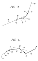
- the Bezier curve 9 is traced to be tangent to a straight line 17 at the point 13.
- the straight line 17 is a bisector which equally divides an angle between a straight line 16 connecting points 11, 13 and a straight line 15 connecting points 12, 13.
- the Bezier curve 9 also needs to be matched at point 19 with the subsequent Bezier curve being next generated.
- the Bezier curve 9 is traced to be tangent to a bisector 20 which equally divides an angle between straight lines, one connecting points 10, 19 and the other connecting points 7, 19.
- the Bezier curve 9 is traced to be tangent to the straight line 17 at point 13 and to the straight line 20 at point 19, including apexes 12, 10.
- Plotting of the Bezier curve 9 is required not only to pass through the four control points 13, 12, 10 and 19, but also to be tangent to the straight lines 17, 19, as discussed above.
- the embodiment adds control points 30, 31 into positions on the tangent lines 17, 19 and nearby the control points 13, 19, respectively.
- the Bezier curve 9 is thus plotted upon the control points 13, 30, 12, 10, 31 and 19.
- the technique for tracing the Bezier curve 9 of Fig. 3 is taken by way of example to describe the present invention, and any other techniques may be used as long as they satisfy tangential conditions.
- Fig. 4 is an illustration for explaining how to trace a Bezier curve 41 subsequent to the Bezier curve 9, in which portions common to the aforementioned drawings are given the same reference numerals.
- FIG. 4 there are shown a vector 40 connecting points 10, 7, a vector 41 connecting points 7, 21, a vector 42 connecting points 21, 22, and a vector 43 connecting points 22, 8.
- An angle between the vectors 40, 41 is calculated respectively from tan-1 (x, y) to obtain a difference which represents an angle of the vector 41 from the vector 40.
- the angle difference of the vector 41 from the vector 40 is "-0.7" in the radian system (where + indicates the clockwise direction and - is the anti-clockwise direction).
- the vector 42 is "-0.6" and the vector 43 is "+0.5".
- of a difference between two angle differences is then calculated. Specifically, an absolute value
- the threshold value is used to change the number of coordinate point groups to be converted into a Bezier curve. If the threshold value is "0.6", the absolute value remains within the threshold value Th until the vector 42 (0.1 ⁇ 0.6), but it exceeds the threshold value Th at the time when the vector 43 appears (1.1>0.6).
- an appropriate Bezier curve can be traced across sections from the initial point 19 to the coordinate point 22, i.e., until the vector 42, but not in the next section since the direction of the vector 43 is remarkably changed.
- a tangent 44 is obtained from two straight lines containing the vectors 41, 42 on both sides of the point 21 by calculating a bisector equally dividing an angle between the two straight lines.
- Fig. 5 is a block diagram showing the main part of a coordinate input device according to the embodiment.
- a digitizer 51 includes a coordinate input surface on which an operator specifies coordinates of data using an input appliance such as pen.
- a coordinate detector 52 detects coordinate positions specified by the operator to the digitizer 51.
- a controller 53 controls operation of the other blocks, and transmits, to a host computer, coordinate data, base point/apex coordinate data indicative of a Bezier curve created upon the coordinate data and such.
- a timer 54 measures predetermined time in accordance with instructions from the controller 53.
- a coordinate memory 55 stores the coordinate data detected by the coordinate detector 52 and input thereto.
- a curve processor 56 produces trigonometric functions based on the coordinate data stored in the coordinate memory 55, or approximate curve data based on coordinate data obtained from angle calculation.
- the coordinate detector 52 actuates the digitizer 51 to generate coordinate data of a point at which the pen is in contact with the coordinate input surface of the digitizer 51.
- the generated coordinate data is output to the coordinate memory 55 and stored therein.
- the controller 53 counts the number of coordinate data to be processed, in response to interrupt pulse signals, and when four or more unprocessed coordinate data have been counted, it actuates the curve processor 56 to start processing apexes.
- the controller 53 transmits to the host computer curve information containing the coordinate data of base points and apexes derived by the curve processor 56.
- the coordinate data of the base points and apexes each include a flag indicative of a particular point at which the coordinate data exists.
- information concerning the number of coordinate data originally contained within a Bezier curve i.e., information indicative of time
- Fig. 6 shows a coordinate input system utilizing an ultrasonic digitizer which is taken by way of example to briefly describe operation for detecting coordinate positions specified to the digitizer 51.
- the working principle of such an ultrasonic digitizer is disclosed, for example, in JP-B-5-62771 and therefore needs not be discussed in detail.
- a vibrator-type or vibratory input pen 63 when a vibrator-type or vibratory input pen 63 is in contact with a surface of a vibration transmitting material 68, if a driving signal is sent thereto from the coordinate detector 52 through a vibrator driver 62, then the vibratory input pen 63 starts vibrating so that the vibration will be transmitted to the vibration transmitting material 68.
- the vibration spreads into the material 68 at an inherent propagation rate and is detected by sensors 66a to 66d provided at four corners. Since the coordinate detector 52 measures the time after the driving signal was output until it reaches the vibratory input pen 63, each distance between the vibratory input pen 63 and the respective sensors 66a to 66d can be calculated from the measured time and the propagation velocity previously measured.
- JP-B-5-62771 among several propagation time applications, a propagation delay time is used for calculating the distance, which is determined by group velocity and phase velocity.
- the calculated distance between the vibratory input pen 63 and each sensor 66a-66d can be used to produce data indicative of the present coordinate position specified by the pen 63 based on the Pythagorean proposition.
- step S1 determination is made at step S1 as to whether the controller 53 instructed the curve processor 56 to start the curve processing. If it has been instructed, the operational procedure goes to step S2, and the curve processor 56 starts reading coordinates of control points input from the digitizer 51 and stored in the coordinate memory 55 in response to signals sequentially output from the controller 53 at timing from the timer 54. The number of unprocessed control points is then counted at the subsequent step S3. If the number is less than four, the operational procedure returns to step S1 and repeats the above processing steps.
- step S5 the curve processor 56 starts processing apexes of a Bezier curve.
- the processing is started at step S5 from calculation of a difference D angle between two angle differences, each between two vectors on both sides of a terminal point, as discussed above. If the absolute value
- step S1 the operational procedure goes to step S9, and it is checked whether there remains any unprocessed point which has been input until then. If not remain, the curve processor 56 stops the curve processing. If remains, it goes to step S10, and the curve processing is executed for the unprocessed point or points before the curve processor 56 stops the curve processing.
- Fig. 8 is an illustration showing a relationship between a Bezier curve and points corresponding to respective coordinate data in the second embodiment of the present invention.
- a Bezier curve 81 is formed by an initial point 82 and a terminal point 83, including apexes 84, 85.
- a point 86 is also displayed as coordinate data provisionally output.
- a certain amount of input coordinate data is converted into a Bezier curve in order of input as the coordinate data are output.
- the Bezier curve is determined by four points, namely, the initial point, terminal point and two apexes so that display points can be calculated therefrom.
- Time required for inputting the terminal point after the initial point was input is also output together with data representative of the Bezier curve.
- the last coordinate data (which has been finally or lastly input) is output as a provisional coordinate data.
- the provisional coordinate data is displayed to point 86.
- the provisional coordinate data is output at each fixed interval or when the operator specifies a position of coordinate data which is located predetermined distance apart or more from the previous provisional point.
- the present invention is not limited by the embodiments and may be applied to any other digitizers such as resistive film type digitizer and electromagnetic digitizer, or pointing devices such as a mouse.
- Each of the embodiments also took a two-dimensional Bezier curve by way of example to describe the present invention, but any other curves may be used instead, such as three-dimensional spline curve, parabolic blending curve and arc.
- the present invention may be applied to a system including a plurality of apparatuses, such as host computer, interface and printer, or to a single apparatus. Further, it can be applied to a case in which all features are implemented in the system or apparatus by supplying a program.
- the present invention will feature a storage medium for storing the program. The program is read out from the storage medium to the system or apparatus so that the system or apparatus can behave according to the program's law.
- the coordinate input device since the coordinate input device produces curve data to be output to the host computer, the work load on the host computer can be reduced.
- the amount of communication data between the host computer and the coordinate input device can be also reduced, or an increasing number of sampling coordinate data can be obtained in the coordinate input device, so that the specified coordinate data can be converted into a curve more approximate to an actual or handwritten curve.
- the coordinate data can be continuously output to the host computer while displaying points indicative of the coordinate data to a display of the host computer, and this permits pen's path to be displayed before the operator hands up the pen, i.e., before the coordinate specification or input is stopped.
- time data may be added to these coordinate data so that the host computer can discriminate a difference in pen pressure, for example, between tap and press.
- the curve can be temporarily displayed to a position closer to the coordinate position from which input of the subsequent coordinate data should be started.
- approximate curve data can be obtained from the specified coordinates.
- the above embodiment also have the advantage of creating a curve more approximate to the specified coordinate data.
- Fig. 9 is a schematic block diagram showing a system structure including a host apparatus and a coordinate input device according to the third embodiment;
- Figs. 10A and 10B are flowcharts showing operation in the embodiment;
- Fig. 11 is an illustration of coordinate strings which represent output information from the coordinate input device according to the embodiment.
- the coordinate input device 101 includes a coordinate detector 102 and a coordinate discriminator 103 for determining whether the coordinates detected by the coordinate detector 102 should be output or not.
- the coordinate detector 102 which may be constituted with one of well-known means, is connected to the input of the coordinate discriminator 103.
- An angle processor 104 and a counter 105 are also connected to the input of the coordinate discriminator 103.
- the angle processor 104 calculates an angle between adjacent two coordinate points previously input and detected, stores the angle therein, and compares the stored angle with the next angle at a coordinate point newly detected.
- the counter 105 counts the number of detected coordinates.
- the angle processor 104 and the counter 105 thus constitute coordinate calculation and processing means for calculating and processing the coordinate data detected by the coordinate detector 102.
- a transmitter 106 is connected to the output of the coordinate discriminator 103.
- the transmitter 106 outputs coordinate information to a host apparatus 107 in accordance with instructions from the coordinate discriminator 103.
- the host apparatus 107 executes all kinds of processings utilizing the coordinate information sent out from the coordinate input device 101.
- the host apparatus 107 includes a curve interpolator 108 for interpolating a curve of the coordinate data from the coordinate input device 101 as required.
- the coordinate strings in Fig. 11 consist of coordinates of a handwritten trace which is input with a pen appliance onto an input surface of the coordinate input device.
- a string of small points typified by 301, 302, 303 and 304 is a coordinate string detected by the coordinate detector 103 of the coordinate input device 101 when one line of the first stroke of a Japanese character was written with the pen appliance on the input surface of the coordinate input device 101.
- Points enclosed with circles and labeled 305, 306 and 307 are coordinates to be output from the coordinate input device 101 to the host apparatus 107. These points are specified by circles each having a fixed radius for convenience sake. Although only the first stroke of the Japanese character is described herein, the second and third strokes are also processed in the same manner as the first stroke was processed and therefore need not be discussed here in further detail.
- the counter 105 is reset, for example, to "2" as an initial value, which indicates the number of coordinate values read in the coordinate detector 102 before the counter starts counting the first coordinate value. Then, the point subsequent to the initial point 301 of the first stroke is read in the coordinate detector 102 at step S205.
- the read coordinate data at that point is transmitted from the transmitter 106 to the host apparatus 107, and the operation for processing this stroke section is finished at step S221.
- step S207 the operational procedure shifts from step S206 to step S207, and calculation is made for an angle formed by two points, one read in at step S202 and the other read in at step S205.
- the angle calculated at step S207 is temporarily stored at step S208, and coordinate data at the subsequent point is read in at step 209.
- step S210 it is determined whether the coordinate data read in at step S209 is the terminal point of the first stroke. If it is the terminal point, the operational procedure jumps to step S220 in the same manner as step S206.
- step S220 the read coordinate data at that point is then transmitted from the transmitter 106 to the host apparatus 107, and the operation for processing this stroke section is finished at step S221.
- the point read herein is not the terminal point of the first stroke, so that it goes to step S211, and calculation is made for an angle formed by the point read in at step S209 and the previous point read in at step S205. Then, a difference between the angle calculated at step S211 and the angle temporarily stored at step S208 is calculated at step S212.
- the difference is compared with a predetermined value a, for example, it is compared with an angle "2 ⁇ /10(rad)" dividing the circle into ten equal parts. If the difference between the angles is larger than the predetermined value a, the operational procedure goes to step S214. If smaller, it branches to step S217.
- step S217 the count value of the counter 105, which represents the number of coordinate data being read in the coordinate detector 102 until then, is compared with a predetermined value X, e.g., it is compared with "10". If the value X is larger than the count value of the counter 105, the operational procedure shifts to step S214.
- the counter 105 Since the count value of the counter 105 remains reset, i.e., it remains at the initial value "2", the counter 105 counts up by one at step S218 and the angle calculated at step S211 is temporarily stored at step S219. After that, the operational procedure returns to step S209.
- a string of points from point 302 through the point previous to point 303 is processed in sequence in the same manner as in the flowcharts of Figs. 10A and 10B.
- step S211 the angle calculated at step S211 is temporarily stored at step S214, and the coordinate data read in at step S209 is transmitted from the transmitter 106 to the host apparatus 107.
- step S216 the count indicative of the number of coordinate data is reset to "0", and the operational procedure returns to step S209.
- step S209 a description will be made to processing operation when the terminal point 304 of the first stroke in Fig. 11 was read in the coordinate detector 102 at step S209 after processing a stroke section from point 303 through the point previous to point 304.
- the coordinate data at point 304 is first read in the coordinate detector 102 at step S209.
- the point 304 is terminal point and therefore the operational procedure jumps to step S220.
- the coordinate data at point 304 is transmitted from the transmitter 106 to the host computer 107 at step S220, and the processing operation is finished at step S221.
- a stroke section to be processed is largely curved, such as a section of the third stroke typified by points labeled 308, 309 and 310 in Fig. 11, since the difference between angles calculated at step S212 is determined at step S213 to be larger than the predetermined value a, the operational procedure goes to step S214, and the coordinate data read in at step S209 is transmitted from the transmitter 106 to the host apparatus 107 at step S215.
- any conventional coordinate input device has been required to output all the coordinate data in each stroke, typified by point 302 in Fig. 11.
- the coordinate input device according to the embodiment can thin out coordinate data, i.e., it can extract only coordinate data at points typified by 301 and 303 and enclosed with circles 305 and 306, thus extremely reducing information content to be transmitted to the host apparatus.
- the predetermined value X to be compared with the number of continuous points read in the coordinate detector 102, and the predetermined value a to be compared with the difference between variable angles may be changed properly, and this makes it possible to extract point information to be transmitted to the host apparatus as optimum characteristics for execution of all kinds of processings in the host apparatus without a special load on the host apparatus.
- Fig. 12 is a schematic block diagram showing a structure of a coordinate input device according to the fourth embodiment
- Fig. 13 is an illustration of a written curve for explaining operation of the coordinate input device according to the embodiment
- Fig. 14 is a illustration of coordinate strings output from a conventional coordinate input device
- Fig. 15 is a illustration of coordinate strings output from the coordinate input device according to the embodiment
- Fig. 16 is a flowchart showing a sequence of operational procedure for execution of curve interpolation in the embodiment in comparison with conventional curve interpolation
- Fig. 17 is an illustration of an exemplary character with interpolated curves which is output from the host apparatus according to the embodiment.
- the embodiment is different from the third embodiment in that an oversampling unit 403 is added into the coordinate input device 101 of Fig. 8 for detecting coordinate data with an oversampling cycle.
- an oversampling unit 403 is added into the coordinate input device 101 of Fig. 8 for detecting coordinate data with an oversampling cycle.
- a coordinate input device 401 there are shown a coordinate input device 401, a coordinate detector 402, a coordinate discriminator 404, an angle processor 405, a counter 406, and a transmitter 407.
- These units have the same functions as the respective corresponding units shown in Fig. 9 and therefore need not be discussed here in further detail.
- a curve 501 is part of handwritten trace which was input to the coordinate input device 401 using an input appliance such as a pen.
- Points 502, 503 and 504 are detected points which were read in the coordinate detector 402, for example, every 10 msec., while points 505, 506 and 507 occurs immediately after detection of the corresponding points 502, 503 and 504, which are detected here as coordinate data after 2 msec.
- each differential vector formed by each point pair i.e., by a point pair 502 and 505, 503 and 506, or 504 and 507, is used as a pseudo tangent vector at each point 502, 503 or 504 to be transmitted to the host apparatus by adding it to the coordinate information selected for transmission to the host apparatus in the same manner as in the first embodiment.
- Fig. 14 shows coordinate strings which were input with an input appliance such as a pen and read in the coordinate detector of the conventional coordinate input device with a fixed sampling cycle.
- the coordinate strings represent Chinese characters which means “trace” and is pronounced “kiseki”.
- the coordinate string information is then output to the host computer.
- Fig. 15 shows coordinate strings which were transmitted from the coordinate input device 401 according to the embodiment to the host computer when inputting handwritten Chinese characters " " with the pen appliance in the same manner as in Fig. 14, in which 701 is a point indicative of selected coordinates and 702 represents a pseudo tangent vector added to the point 701.
- the pseudo tangent vector 702 is lengthened to facilitate the description.
- Such a structure of the embodiment permits the host apparatus to easily execute curve interpolation using the coordinate data from the coordinate input device 401.
- Fig. 16 shows a comparison between operational procedure for executing conventional curve interpolation (steps S801 through S809) and operational procedure for executing curve interpolation according to the embodiment.
- the former operation is performed in the conventional curve interpolator 108 utilized in the third embodiment of Fig. 9 for calculating the curve as a curve function based on the coordinate string information from the coordinate input device 101.
- the latter operation is performed for calculating the curve as a curve function based on the coordinate string information which additionally contains information indicative of pseudo tangent vectors at respective coordinate points according to the embodiment.
- steps S801 and S807 are commonly used in both the calculation systems for reading data of coordinate strings, and steps S802 and S808 are commonly used for calculating the distance between data to be made approximate.
- a matrix calculation technique is generally used to calculate a tangent vector at each data point from each data of coordinate strings.
- Steps S803 through S805 show the processing steps of calculating the tangent vector at each data point using such a matrix calculation technique.
- the calculation technique according to the embodiment can directly enter the final step S809 (step S806 in the conventional) of calculating a spline curve without any matrix calculation since the pseudo tangent vector at each data point has been already obtained.
- Fig. 17 shows an exemplary output of the host computer when inputting handwritten Chinese characters with the pen, in which curve interpolation according to the embodiment has been already done.
- the oversampling unit 403 in the coordinate input device 401 can obtain a pseudo tangent vector at each data point, and this makes it possible to easily execute curve interpolation with less work load on the host apparatus than the conventional. Accordingly, the processing can be performed with higher accuracy and at a higher rate than the conventional calculation technique which involves a sequence of matrix calculating steps.
- the coordinate discriminator selects data among the coordinate data detected based on the coordinate information and by the calculation means consisting of the angle processor and the counter so that only the data selected by the coordinate discriminator can be output to the transmitter. For this reason, the coordinate input device can transmits the coordinate information to the host apparatus with less information content but as effective coordinate information. This permits the host apparatus to process the coordinate information properly with higher accuracy and at a higher rate than the conventional.
- the coordinate input device also includes the oversampling unit so that the distance difference between two data can be output to the host apparatus, one data from the coordinate detector and the other data obtained by the oversampling unit after a slight delay since the coordinate detector obtained the data. This also permits the host computer to process coordinate information more properly with higher accuracy and at a higher rate.
- Fig. 20 is an illustration for explaining sampling timing in the fifth embodiment.
- difference approximation with a first difference method is used to calculate data corresponding to a tangent vector based on the input from a digitizer.
- Tn is a sampling cycle and each black circle represents data point sampled with the sampling cycle Tn.
- a time interval T (e.g., 2 msec.) is then set to be shorter than the sampling cycle Tn, so as to get a sample of data again at the end of the time interval T after the normal sampling was done with the cycle Tn.
- ⁇ is a constant and may be properly defined in each curve processing system.
- the embodiment is configured to get a sample of data again at the end of a short time interval after the normal sampling was done with the normal sampling cycle. For this reason, an approximate value of a tangent vector at the normally sampled coordinate point can be obtained in a short time. The use of such a tangent vector facilitates faithful reproduction of the input trace.
- the embodiment also simplifies the procedure for curve approximation and therefore enables the host apparatus to output a faithfully reproduced trace. This makes it possible to reduce the number of sampling data conventionally required. Since the number of data can be reduced with the same display quality, the work load on the host apparatus can be also reduced.
- the sampling time for difference approximation is shorter than the normal sampling cycle and therefore requires less data content than that of the normal coordinate data.
- the coordinate data obtained by the normal sampling is 16 bits
- the amount of difference ⁇ X, ⁇ Y can express several bits or so, thus reducing the amount of data transmission.
- Fig. 21 is a schematic block diagram showing a structure of an ultrasonic digitizer according to the embodiment.
- a controller 1 drives a built-in vibrator 4 of the pen 3 through a vibrator driver 2.
- the vibration generated by the vibrator 4 spreads into the material 8 at an inherent propagation rate and is converted into electric waveforms (signal waveform) by sensors 6a to 6d provided at four corners.
- the signal waveforms are detected by a signal waveform detector 9 and transmitted to the controller 1.
- the controller 1 measures the time after the vibrator 4 started vibrating until the vibration reaches the respective sensors 6a to 6d, and calculates each distance between the pen 3 and the sensors 6a to 6d from the measured time and the propagation velocity of the vibration transmitting material 8 previously measured.
- a propagation delay time is used for calculating the distance, the propagation delay time determined by group velocity and phase velocity.
- the calculated distance between the pen and each sensor can be used, based on the Pythagorean proposition, to produce data indicative of the present coordinate position at which the pen 3 is in contact with the vibration transmitting material 8.
- the controller 1 then calculates an input trace from the input coordinate position and displays it on a display 11 such as a liquid crystal display through a display driver 10.
- Such a coordinate detecting operation can be repeated every normal sampling cycle, e.g., every 10 [msec.], to detect normal coordinate data (marked with black circles in Fig. 20).
- the operation can be also repeated at the end of the time interval T (2 msec. in the embodiment) after the normal sampling was done so as to get a sample of data again, thus obtaining data corresponding to a tangent vector as discussed above.
- the operation may be carried out under control of the controller 1 using a control program.
- the control program will be described below in further detail with reference to Fig. 22.
- Fig. 22 is a flowchart showing operation in the embodiment.
- the control program used herein is stored in a ROM, not shown, and executed by an unillustrated CPU, the ROM and the CPU both incorporated in the controller 1.
- the control program may be supplied from a storage medium such as a floppy disk to the apparatus.
- the sampling cycle Tn and the time interval T are set at step S1.
- the count may be set to a cycle of 10 [msec.] as well as set to a special timing at which supplemental sampling can be done.
- a first counter counting 1 msec clock is set to "10”
- the first counter starts normal sampling with the normal cycle Tn. Subsequently, the first counter continuously repeats counting until the power is turned off.
- the first counter is checked to determine whether the present timing is first sampling timing, i.e., whether it is sampling timing of the cycle Tn. If not the first sampling timing, the control procedure provides a feedback loop and waits until the first sampling timing appears. If it is the first sampling timing, the control procedure goes to step S4 and first sampling data is obtained. Thus, the normal sampling of the cycle Tn is performed.
- the second counter After the end operation of the first sampling, the second counter starts at step S5 and determines second sampling timing.
- the second counter is configured to count a time interval T as mentioned above. If the time interval T is 2 [msec], the second counter will be required to monitor whether 2 [msec] has elapsed or not.
- the control procedure provides a feedback loop. If once the time interval T has elapsed, the control procedure goes to step S7 and second sampling is performed for obtaining second data. After the second data was obtained, the second counter is stopped and cleared at step S8.
- the first data is first sampling data obtained at sampling timing of the cycle Tn and the second data is second sampling data obtained at the end of the time interval T after the first data was obtained.
- the current data is compared with the previous output data and determined as to whether the current data should be output or not. The determination is made through several comparison steps (not shown) at which several comparative elements are used such as the changed amount from the previous output data, the length or angle, sampling frequency between the current data and the previous output data, and the number of skipped data.
- points (data points) are extracted from the sampling data and output, so that the data content to be processed can be reduced, thereby carrying out high speed operation.
- the previous output data is stored in the RAM, not shown, in the controller 1 for comparison with the current sampling data.
- an angle between the current data and the previous output data may be detected.
- the current sampling data is adopted only when the angle is a predetermined angle or more (e.g., 30 degree or more).
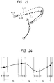
- Fig. 23 shows a concrete example of such operation using a Japanese character pronounced "a".
- a point 4-0 marked with a white dot is sampling data
- points 4-3a to 4-3g each marked with a white circle are data used as data points
- a point 4-1 marked with a black dot represents the result of interpolation.
- there is less change at the beginning of the character (at the beginning of the first stroke) the sampling data are not adopted as data points, i.e., all the points from 4-3a to 4-3b are not used as data points.
- the data point When it is determined whether the sampling data is adapted or not only from the angle change, the data point may not be output for quite a long time such as to be independent of any vector. It is therefore desirable, when the number of non-selected sampling points (skipped sampling points) became a predetermined value or more, to use the subsequent sampling data as a data point irrespective of the angle change. For example, the data point 4-3b was adopted due to the number of skipped sampling points over the predetermined value, whereas the data point 4-3c was adopted due to a large angle change. Although this determination used the number of skipped sampling data as a criterion, it may use the distance between a position of the previous output data and a position of the current sampling data. In this case, it is required to calculate the distance between data, but not count the sampling data to be skipped.
- Any other criterion may be also used to determine whether the data point should be adopted or not.
- step S10 if the determination was made at step S11 that the current data is data not to be output, the control procedure returns to step S3 and the next sampling is started. If the first data currently checked is data to be output, the first data and the associated difference data are output to an unillustrated host apparatus at step S12.
- step S13 After the data output to the host apparatus is then stored in an unillustrated memory of the controller 1 (step S13) for the next determination, the control procedure returns to the sampling loop.
- the determination at step S10 was concretely described above, the present invention is not limited thereto, and the determining method and criterion may be selected properly according to the system.
- FIG. 23 is an illustration of exemplary handwritten input to which the embodiment is applied.
- Fig. 23 there are shown two display examples, one an interpolation example 4-2 (marked with crosses) which was interpolated by a three-dimensional spline technique using only the normal sampling data, and the other an interpolation example 4-1 (marked with black dots) according to the embodiment which was interpolated using finite differences.
- a comparison between the examples shows that the representation 4-1 (black dots) using the difference data is almost equal to the actual handwritten input (marked with white dots).
- the representation 4-2 (crosses) using the three-dimensional spline technique is largely deviated from the actual handwritten input (white dots).
- the actual handwritten input (4-0) can be approximately reproduced only by using, at steps S10 and S11, the angle change of the coordinate sampling point (4-0) and the data points (4-3a through 4-3g) extracted according to a criterion such as the number of data, so that the data content can be also reduced to a degree.
- the interpolated curve is not limited thereto, and other curve functions such as Bezier curve and B-spline may be applicable.
- the embodiment used a time relationship in which the difference sampling point is located behind the corresponding sampling point, but the present invention is not limited by the embodiment.
- the different sampling point may be located before the corresponding sampling point.
- the obtained difference data is the first order.
- a sixth embodiment described herein is to expand the difference data to the second order.
- Such second difference data may be used in a case that a need exists to obtain information corresponding to a derivative of the second order at the point. For example, it is desirably used in a case that continuity should be considered such as contact in a three-dimensional approximate curve.
- Fig. 24 shows sampling timing in the sixth embodiment.
- two difference sampling points (marked with the white dots) are provided before and behind one normal sampling point (marked with the black dot).
- T is a difference sampling time and ⁇ is a constant for adjusting the size of a vector as similar to those in the fifth embodiment.
- the ultrasonic digitizer as shown in the above embodiments may be used at first to read in only time data at respective sampling timing, and then, to execute the coordinate processing and difference calculation.
- Such configuration control permits an interval between difference sampling points to be set shorter and therefore the sampling time interval to be reduced.
- any other type of coordinate input device may be applicable. Even in any type of coordinate input device, the same expected results will be obtained as long as sampling is performed using a normal sampling cycle and a time interval for difference sampling in combination in a manner similar to those shown in the above embodiments.
- the present invention is not limited to the coordinate input device, and is may be applied to other devices such as A/D converters
- the use of such devices to get samples of all kinds of sensing signals such as a sound or video signal, heat, light, vibration and moving direction of an object, may realize reduction of data content and faithful reproduction of input data as similar to the above embodiments.
- samples of data are obtained with a normal sampling cycle and difference data are obtained at sampling timing before and/or after the normal sampling timing of the normal sampling cycle, so that data corresponding to a derivative of the first order or second order at the point can be obtained.
- the use of the data corresponding to the derivative may reduce the number of data and hence the work load on the host apparatus as well as enables a faithful reproduction of the input trace.
- the application to a coordinate input device as discussed in the above embodiments permits addition of data indicative of a directional component to the coordinate data at each sampling point as it was used as only a passing point in the conventional, so that the number of coordinate data can be reduced as well as the faithful reproduction of the input trace can be realized irrespective of display size.
- the present invention may be applied to a system including a plurality of apparatuses, or to a single apparatus. Further, it can be applied to a case in which all features are implemented in the system or apparatus by supplying a program.
- the present invention will feature a storage medium for storing the program. The program is read out from the storage medium to the system or apparatus so that the system or apparatus can behave in a predetermined manner.
- interpolation of sampling data can be made more faithfully approximate to the input data with less input data and in simpler computing.
- the present invention is capable of obtaining a trace more approximate to the input trace indicated by input data with less coordinate information and in simpler computing.
- the present invention also enables addition of information which represents a direction of the input trace at each coordinate sampling point. This makes it possible to obtain a trace further approximate to the input trace with less coordinate information and in simpler computing.
- a coordinate input device capable of interpolation of sampling data more faithful to input data with less input data and in simpler computing.
- the input data (coordinate information indicative of an input trace) are sampled both with a predetermined cycle (Tn) and at the end of a predetermined time interval after the sampling of the cycle Tn was done.
- Tn predetermined cycle
- information indicative of a tangent vector at each coordinate point on the input trace can be obtained.
- the coordinate point and the associated tangent vector information are thus output, so that a trace more faithful to the input trace can be obtained with less coordinate points.
Landscapes
- Engineering & Computer Science (AREA)
- General Engineering & Computer Science (AREA)
- Theoretical Computer Science (AREA)
- Human Computer Interaction (AREA)
- Physics & Mathematics (AREA)
- General Physics & Mathematics (AREA)
- Character Discrimination (AREA)
- User Interface Of Digital Computer (AREA)
- Image Processing (AREA)
- Processing Or Creating Images (AREA)
- Image Generation (AREA)
Applications Claiming Priority (9)
| Application Number | Priority Date | Filing Date | Title |
|---|---|---|---|
| JP223589/95 | 1995-08-31 | ||
| JP22358995 | 1995-08-31 | ||
| JP7223589A JPH0969022A (ja) | 1995-08-31 | 1995-08-31 | サンプリング方法及び装置及び情報処理装置 |
| JP268059/95 | 1995-09-22 | ||
| JP26805995 | 1995-09-22 | ||
| JP26805995A JP3517496B2 (ja) | 1995-09-22 | 1995-09-22 | 座標入力装置および座標入力方法 |
| JP26286995 | 1995-10-11 | ||
| JP262869/95 | 1995-10-11 | ||
| JP26286995A JPH09106321A (ja) | 1995-10-11 | 1995-10-11 | 座標入力方法及びその装置 |
Publications (3)
| Publication Number | Publication Date |
|---|---|
| EP0762265A2 true EP0762265A2 (de) | 1997-03-12 |
| EP0762265A3 EP0762265A3 (de) | 1997-06-11 |
| EP0762265B1 EP0762265B1 (de) | 2003-05-28 |
Family
ID=27330803
Family Applications (1)
| Application Number | Title | Priority Date | Filing Date |
|---|---|---|---|
| EP96113922A Expired - Lifetime EP0762265B1 (de) | 1995-08-31 | 1996-08-30 | Koordinateneingabevorrichtung und Methode |
Country Status (5)
| Country | Link |
|---|---|
| US (1) | US6278445B1 (de) |
| EP (1) | EP0762265B1 (de) |
| KR (1) | KR100269680B1 (de) |
| CN (1) | CN1098496C (de) |
| DE (1) | DE69628380T2 (de) |
Cited By (14)
| Publication number | Priority date | Publication date | Assignee | Title |
|---|---|---|---|---|
| EP1037135A3 (de) * | 1999-03-18 | 2002-12-04 | Samsung Electronics Co., Ltd. | Verarbeitungsverfahren der durch einen Benutzer eingebenen Information auf den berührungsempfindlichen Bildschirm einer digitalen Mobilstation |
| US6970599B2 (en) | 2002-07-25 | 2005-11-29 | America Online, Inc. | Chinese character handwriting recognition system |
| CN1331637C (zh) * | 2005-04-06 | 2007-08-15 | 南京师范大学 | 异性切刀波浪刃口的开刃和刃磨方法 |
| US8201087B2 (en) | 2007-02-01 | 2012-06-12 | Tegic Communications, Inc. | Spell-check for a keyboard system with automatic correction |
| US8225203B2 (en) | 2007-02-01 | 2012-07-17 | Nuance Communications, Inc. | Spell-check for a keyboard system with automatic correction |
| US8456441B2 (en) | 2003-04-09 | 2013-06-04 | Tegic Communications, Inc. | Selective input system and process based on tracking of motion parameters of an input object |
| US8466896B2 (en) | 1999-05-27 | 2013-06-18 | Tegic Communications, Inc. | System and apparatus for selectable input with a touch screen |
| US8576167B2 (en) | 1999-05-27 | 2013-11-05 | Tegic Communications, Inc. | Directional input system with automatic correction |
| EP2282253A3 (de) * | 2009-07-29 | 2014-03-19 | Nintendo Co., Ltd. | Koordinatenberechnungsverfahren |
| WO2016044214A1 (en) * | 2014-09-15 | 2016-03-24 | Microsoft Technology Licensing, Llc | Smooothing and gpu-enabled rendering of digital ink |
| EP2573658A4 (de) * | 2010-05-21 | 2016-07-13 | Nec Corp | Vorrichtung zur bestimmung einer festgelegten position für einen berührungsbildschirm, berührungsbildschirmvorrichtung, verfahren zur bestimmung einer festgelegten position für einen berührungsbildschirm und computerprogramm-speichermedium |
| US9400782B2 (en) | 1999-05-27 | 2016-07-26 | Nuance Communications, Inc. | Virtual keyboard system with automatic correction |
| WO2017007451A1 (en) * | 2015-07-07 | 2017-01-12 | Landmark Graphics Corporation | Tri-cubic and hybrid interpolation in a 3d texture shader |
| CN107980109A (zh) * | 2017-01-04 | 2018-05-01 | 深圳配天智能技术研究院有限公司 | 机器人运动轨迹规划方法及相关装置 |
Families Citing this family (36)
| Publication number | Priority date | Publication date | Assignee | Title |
|---|---|---|---|---|
| US6408085B1 (en) * | 1998-07-22 | 2002-06-18 | Space Imaging Lp | System for matching nodes of spatial data sources |
| ATE443946T1 (de) * | 1999-05-27 | 2009-10-15 | Tegic Communications Inc | Tastatursystem mit automatischer korrektur |
| US7610194B2 (en) * | 2002-07-18 | 2009-10-27 | Tegic Communications, Inc. | Dynamic database reordering system |
| US6636217B1 (en) * | 2000-05-11 | 2003-10-21 | Autodesk, Inc. | Regularized tangents in computer graphics |
| US6771266B2 (en) * | 2001-01-16 | 2004-08-03 | Microsoft Corporation | Method and apparatus for improving the appearance of digitally represented handwriting |
| AUPR890201A0 (en) * | 2001-11-16 | 2001-12-06 | Silverbrook Research Pty. Ltd. | Methods and systems (npw005) |
| US6654016B1 (en) * | 2001-11-30 | 2003-11-25 | Microsoft Corporation | System and method for efficiently creating splines |
| JP4061094B2 (ja) * | 2002-03-15 | 2008-03-12 | インターナショナル・ビジネス・マシーンズ・コーポレーション | 音声認識装置、その音声認識方法及びプログラム |
| JP2004355098A (ja) * | 2003-05-27 | 2004-12-16 | Fujitsu Component Ltd | 超音波座標入力装置及び超音波座標入力方法 |
| JP4213052B2 (ja) * | 2004-01-28 | 2009-01-21 | 任天堂株式会社 | タッチパネル入力を用いたゲームシステム |
| JP4159491B2 (ja) * | 2004-02-23 | 2008-10-01 | 任天堂株式会社 | ゲームプログラムおよびゲーム装置 |
| JP2005346467A (ja) * | 2004-06-03 | 2005-12-15 | Nintendo Co Ltd | 図形認識プログラム |
| KR100723402B1 (ko) * | 2005-02-15 | 2007-05-30 | 삼성전자주식회사 | 제스처 인식장치와 방법 및 컴퓨터 프로그램을 저장하는 컴퓨터로 읽을 수 있는 기록매체 |
| JP4717489B2 (ja) * | 2005-04-07 | 2011-07-06 | 任天堂株式会社 | ゲームプログラム |
| FR2925708B1 (fr) * | 2007-12-20 | 2009-12-18 | Dav | Procede de detection d'une variation angulaire d'une trajectoire de commande sur une surface tactile et module de commande correspondant |
| JP5464819B2 (ja) * | 2008-04-30 | 2014-04-09 | キヤノン株式会社 | 動画像処理装置および方法、プログラム |
| CN101751200B (zh) * | 2008-12-09 | 2012-01-11 | 北京三星通信技术研究有限公司 | 移动终端的空间输入法及其实现装置 |
| JP5324391B2 (ja) * | 2009-10-22 | 2013-10-23 | キヤノン株式会社 | 画像処理装置およびその制御方法 |
| JP5537121B2 (ja) * | 2009-10-30 | 2014-07-02 | キヤノン株式会社 | 画像処理装置およびその制御方法 |
| FR2959331B1 (fr) * | 2010-04-22 | 2013-03-29 | St Microelectronics Rousset | Procede et dispositif d'authentification d'un utilisateur a l'aide de donnees biometriques. |
| US20120050293A1 (en) * | 2010-08-25 | 2012-03-01 | Apple, Inc. | Dynamically smoothing a curve |
| WO2012075629A1 (en) * | 2010-12-08 | 2012-06-14 | Nokia Corporation | User interface |
| CN102622120B (zh) * | 2011-01-31 | 2015-07-08 | 宸鸿光电科技股份有限公司 | 多点触控面板的触碰轨迹追踪方法 |
| DE112011105035T5 (de) * | 2011-03-14 | 2014-01-02 | Mitsubishi Electric Corporation | Folgenanordnungsvorrichtung |
| TWI442279B (zh) * | 2011-07-18 | 2014-06-21 | Acer Inc | 多重取樣頻率電路及方法 |
| US9442598B2 (en) * | 2013-02-08 | 2016-09-13 | Synaptics Incorporated | Detecting interference in an input device having electrodes |
| DE102013009376A1 (de) * | 2013-06-05 | 2014-12-24 | Voith Patent Gmbh | Welle |
| JP2015069284A (ja) | 2013-09-27 | 2015-04-13 | 株式会社リコー | 画像処理装置 |
| JP6315271B2 (ja) * | 2013-11-13 | 2018-04-25 | ブラザー工業株式会社 | 電子筆記装置及び電子筆記処理プログラム並びにデータ処理方法 |
| CN105765502B (zh) | 2013-11-19 | 2019-10-08 | 株式会社和冠 | 用于墨水数据生成、墨水数据呈现、墨水数据操纵以及墨水数据通信的方法和系统 |
| US20150241970A1 (en) * | 2014-02-27 | 2015-08-27 | Samsung Electronics Co., Ltd. | Method and apparatus for providing haptic effect |
| JP6539032B2 (ja) | 2014-10-06 | 2019-07-03 | キヤノン株式会社 | 表示制御装置、表示制御方法、およびプログラム |
| TWI620097B (zh) * | 2016-12-30 | 2018-04-01 | 漳州立達信光電子科技有限公司 | 輸入方法及使用該輸入方法的觸控裝置、手勢偵測裝置、電腦可讀取紀錄媒體、及電腦程式產品 |
| US11158097B2 (en) * | 2019-08-19 | 2021-10-26 | Remarkable As | Generating vector graphics by processing raster graphics |
| CN110716493B (zh) * | 2019-09-10 | 2022-03-04 | 天津大学 | 一种五轴微线段加工路径光顺方法 |
| CN110703289B (zh) * | 2019-10-29 | 2021-07-06 | 杭州鸿泉物联网技术股份有限公司 | 轨迹数据上报方法及移动轨迹还原方法 |
Family Cites Families (14)
| Publication number | Priority date | Publication date | Assignee | Title |
|---|---|---|---|---|
| US4510568A (en) | 1981-05-25 | 1985-04-09 | Fanuc Ltd. | Graphic processing method |
| JPS60222917A (ja) * | 1984-04-20 | 1985-11-07 | Oki Electric Ind Co Ltd | イメ−ジデ−タ伝送装置 |
| JPS62154078A (ja) | 1985-12-26 | 1987-07-09 | Fujitsu Ltd | オンライン手書文字認識における特徴点の抽出方式 |
| JPH0621170B2 (ja) | 1986-03-25 | 1994-03-23 | ダイアホイルヘキスト株式会社 | 2軸延伸ポリエステルフイルム |
| DE3779019D1 (de) | 1986-06-27 | 1992-06-17 | Canon Kk | Koordinateneingabegeraet. |
| JPS636619A (ja) | 1986-06-27 | 1988-01-12 | Canon Inc | 入力装置 |
| JPH03154122A (ja) * | 1989-11-10 | 1991-07-02 | Hitachi Ltd | 座標入力サンプリング方式 |
| US5392058A (en) * | 1991-05-15 | 1995-02-21 | Sharp Kabushiki Kaisha | Display-integrated type tablet device |
| JPH05159036A (ja) * | 1991-12-04 | 1993-06-25 | Canon Inc | 描画方法及びその装置 |
| US5491305A (en) * | 1992-01-24 | 1996-02-13 | Canon Kabushiki Kaisha | Vibration transmission plate for inputting coordinates |
| JPH05233136A (ja) * | 1992-02-25 | 1993-09-10 | Nitsuko Corp | 座標入力装置 |
| US5329625A (en) | 1992-04-15 | 1994-07-12 | International Business Machines Corp. | System to service processor interface for a tablet computer |
| JP2570954B2 (ja) | 1993-01-26 | 1997-01-16 | 日本電気株式会社 | 3次元スプラインの次元変換時の直線形状判定方法 |
| JPH0844485A (ja) * | 1994-07-29 | 1996-02-16 | Canon Inc | 座標入力装置 |
-
1996
- 1996-08-27 US US08/697,278 patent/US6278445B1/en not_active Expired - Fee Related
- 1996-08-30 DE DE69628380T patent/DE69628380T2/de not_active Expired - Fee Related
- 1996-08-30 CN CN96113011A patent/CN1098496C/zh not_active Expired - Fee Related
- 1996-08-30 EP EP96113922A patent/EP0762265B1/de not_active Expired - Lifetime
- 1996-08-31 KR KR1019960037479A patent/KR100269680B1/ko not_active Expired - Fee Related
Cited By (26)
| Publication number | Priority date | Publication date | Assignee | Title |
|---|---|---|---|---|
| US7031756B1 (en) | 1999-03-18 | 2006-04-18 | Samsung Electronics Co., Ltd | Method of processing user information inputted through touch screen panel of digital mobile station |
| EP1037135A3 (de) * | 1999-03-18 | 2002-12-04 | Samsung Electronics Co., Ltd. | Verarbeitungsverfahren der durch einen Benutzer eingebenen Information auf den berührungsempfindlichen Bildschirm einer digitalen Mobilstation |
| US8576167B2 (en) | 1999-05-27 | 2013-11-05 | Tegic Communications, Inc. | Directional input system with automatic correction |
| US8466896B2 (en) | 1999-05-27 | 2013-06-18 | Tegic Communications, Inc. | System and apparatus for selectable input with a touch screen |
| US9400782B2 (en) | 1999-05-27 | 2016-07-26 | Nuance Communications, Inc. | Virtual keyboard system with automatic correction |
| US9557916B2 (en) | 1999-05-27 | 2017-01-31 | Nuance Communications, Inc. | Keyboard system with automatic correction |
| US6970599B2 (en) | 2002-07-25 | 2005-11-29 | America Online, Inc. | Chinese character handwriting recognition system |
| US8456441B2 (en) | 2003-04-09 | 2013-06-04 | Tegic Communications, Inc. | Selective input system and process based on tracking of motion parameters of an input object |
| CN1331637C (zh) * | 2005-04-06 | 2007-08-15 | 南京师范大学 | 异性切刀波浪刃口的开刃和刃磨方法 |
| US8892996B2 (en) | 2007-02-01 | 2014-11-18 | Nuance Communications, Inc. | Spell-check for a keyboard system with automatic correction |
| US9092419B2 (en) | 2007-02-01 | 2015-07-28 | Nuance Communications, Inc. | Spell-check for a keyboard system with automatic correction |
| US8225203B2 (en) | 2007-02-01 | 2012-07-17 | Nuance Communications, Inc. | Spell-check for a keyboard system with automatic correction |
| US8201087B2 (en) | 2007-02-01 | 2012-06-12 | Tegic Communications, Inc. | Spell-check for a keyboard system with automatic correction |
| EP2282253A3 (de) * | 2009-07-29 | 2014-03-19 | Nintendo Co., Ltd. | Koordinatenberechnungsverfahren |
| US9833706B2 (en) | 2009-07-29 | 2017-12-05 | Nintendo Co., Ltd. | Storage medium having information processing program stored therein, information processing device, and coordinate calculation method |
| EP2573658A4 (de) * | 2010-05-21 | 2016-07-13 | Nec Corp | Vorrichtung zur bestimmung einer festgelegten position für einen berührungsbildschirm, berührungsbildschirmvorrichtung, verfahren zur bestimmung einer festgelegten position für einen berührungsbildschirm und computerprogramm-speichermedium |
| WO2016044214A1 (en) * | 2014-09-15 | 2016-03-24 | Microsoft Technology Licensing, Llc | Smooothing and gpu-enabled rendering of digital ink |
| CN106687891A (zh) * | 2014-09-15 | 2017-05-17 | 微软技术许可有限责任公司 | 数字墨水的平滑和gpu使能的渲染 |
| US9697625B2 (en) | 2014-09-15 | 2017-07-04 | Microsoft Technology Licensing, Llc | Smoothing and GPU-enabled rendering of digital ink |
| US9508166B2 (en) | 2014-09-15 | 2016-11-29 | Microsoft Technology Licensing, Llc | Smoothing and GPU-enabled rendering of digital ink |
| CN106687891B (zh) * | 2014-09-15 | 2019-12-03 | 微软技术许可有限责任公司 | 数字墨水的平滑和gpu使能的渲染 |
| AU2015318093B2 (en) * | 2014-09-15 | 2020-06-04 | Microsoft Technology Licensing, Llc | Smoothing and GPU-enabled rendering of digital ink |
| WO2017007451A1 (en) * | 2015-07-07 | 2017-01-12 | Landmark Graphics Corporation | Tri-cubic and hybrid interpolation in a 3d texture shader |
| GB2554327A (en) * | 2015-07-07 | 2018-03-28 | Landmark Graphics Corp | Tri-cubic and hybrid interpolation in a 3D texture shader |
| US10319140B2 (en) | 2015-07-07 | 2019-06-11 | Landmark Graphics Corporation | Tri-cubic and hybrid interpolation in a 3D texture shader |
| CN107980109A (zh) * | 2017-01-04 | 2018-05-01 | 深圳配天智能技术研究院有限公司 | 机器人运动轨迹规划方法及相关装置 |
Also Published As
| Publication number | Publication date |
|---|---|
| US6278445B1 (en) | 2001-08-21 |
| CN1098496C (zh) | 2003-01-08 |
| CN1151555A (zh) | 1997-06-11 |
| EP0762265A3 (de) | 1997-06-11 |
| DE69628380T2 (de) | 2004-04-01 |
| EP0762265B1 (de) | 2003-05-28 |
| KR100269680B1 (ko) | 2000-10-16 |
| DE69628380D1 (de) | 2003-07-03 |
| KR970012113A (ko) | 1997-03-29 |
Similar Documents
| Publication | Publication Date | Title |
|---|---|---|
| EP0762265B1 (de) | Koordinateneingabevorrichtung und Methode | |
| KR100465241B1 (ko) | 가상 필기 평면을 이용한 모션 인식 시스템 및 그 인식방법 | |
| US6278443B1 (en) | Touch screen with random finger placement and rolling on screen to control the movement of information on-screen | |
| CN1121662C (zh) | 以直线段为主的手写体字符的预处理方法和手写体识别设备 | |
| US5155813A (en) | Computer apparatus for brush styled writing | |
| JP4177335B2 (ja) | 手書き文字入力装置および手書き文字入力処理方法 | |
| US5933149A (en) | Information inputting method and device | |
| JP3416325B2 (ja) | 座標入力装置及びその制御方法 | |
| EP0383304A2 (de) | Koordinateneingabevorrichtung | |
| US5636336A (en) | Graphics processing unit for use with a stylus pen and tablet, and method therefore | |
| JPH0683522A (ja) | 座標入力方式 | |
| JPH09106321A (ja) | 座標入力方法及びその装置 | |
| EP0509996B1 (de) | Rechner für pinselmodelliertes schreiben | |
| JP3990799B2 (ja) | 座標入力装置及びその制御方法、コンピュータ可読メモリ | |
| JPH08328724A (ja) | データ入力方法とその装置 | |
| JP2592971B2 (ja) | 座標出力方法及びその装置 | |
| JPH07121152A (ja) | マウスによるポインティング方法 | |
| JPH0683525A (ja) | 座標入力制御方法及び装置 | |
| JP2002366294A (ja) | データ入力装置およびそのプログラム | |
| JPH09185454A (ja) | 座標入力方法及びその装置 | |
| JPH08241170A (ja) | 手書き入力装置 | |
| JPH0969022A (ja) | サンプリング方法及び装置及び情報処理装置 | |
| JPH0962837A (ja) | 線分拡大描画方法および線分拡大描画装置 | |
| JPH07306747A (ja) | 入力座標変換方法およびその装置 | |
| KR19990059505A (ko) | 휴대 정보 단말기를 이용한 펜입력 방법 및 장치 |
Legal Events
| Date | Code | Title | Description |
|---|---|---|---|
| PUAI | Public reference made under article 153(3) epc to a published international application that has entered the european phase |
Free format text: ORIGINAL CODE: 0009012 |
|
| AK | Designated contracting states |
Kind code of ref document: A2 Designated state(s): DE FR GB IT NL |
|
| PUAL | Search report despatched |
Free format text: ORIGINAL CODE: 0009013 |
|
| AK | Designated contracting states |
Kind code of ref document: A3 Designated state(s): DE FR GB IT NL |
|
| 17P | Request for examination filed |
Effective date: 19971028 |
|
| 17Q | First examination report despatched |
Effective date: 20010716 |
|
| GRAH | Despatch of communication of intention to grant a patent |
Free format text: ORIGINAL CODE: EPIDOS IGRA |
|
| GRAH | Despatch of communication of intention to grant a patent |
Free format text: ORIGINAL CODE: EPIDOS IGRA |
|
| GRAA | (expected) grant |
Free format text: ORIGINAL CODE: 0009210 |
|
| AK | Designated contracting states |
Designated state(s): DE FR GB IT NL |
|
| PG25 | Lapsed in a contracting state [announced via postgrant information from national office to epo] |
Ref country code: NL Free format text: LAPSE BECAUSE OF FAILURE TO SUBMIT A TRANSLATION OF THE DESCRIPTION OR TO PAY THE FEE WITHIN THE PRESCRIBED TIME-LIMIT Effective date: 20030528 Ref country code: IT Free format text: LAPSE BECAUSE OF FAILURE TO SUBMIT A TRANSLATION OF THE DESCRIPTION OR TO PAY THE FEE WITHIN THE PRESCRIBED TIME-LIMIT;WARNING: LAPSES OF ITALIAN PATENTS WITH EFFECTIVE DATE BEFORE 2007 MAY HAVE OCCURRED AT ANY TIME BEFORE 2007. THE CORRECT EFFECTIVE DATE MAY BE DIFFERENT FROM THE ONE RECORDED. Effective date: 20030528 Ref country code: FR Free format text: LAPSE BECAUSE OF FAILURE TO SUBMIT A TRANSLATION OF THE DESCRIPTION OR TO PAY THE FEE WITHIN THE PRESCRIBED TIME-LIMIT Effective date: 20030528 |
|
| REG | Reference to a national code |
Ref country code: GB Ref legal event code: FG4D |
|
| REF | Corresponds to: |
Ref document number: 69628380 Country of ref document: DE Date of ref document: 20030703 Kind code of ref document: P |
|
| NLV1 | Nl: lapsed or annulled due to failure to fulfill the requirements of art. 29p and 29m of the patents act | ||
| PLBE | No opposition filed within time limit |
Free format text: ORIGINAL CODE: 0009261 |
|
| STAA | Information on the status of an ep patent application or granted ep patent |
Free format text: STATUS: NO OPPOSITION FILED WITHIN TIME LIMIT |
|
| 26N | No opposition filed |
Effective date: 20040302 |
|
| EN | Fr: translation not filed | ||
| PGFP | Annual fee paid to national office [announced via postgrant information from national office to epo] |
Ref country code: DE Payment date: 20080831 Year of fee payment: 13 |
|
| PGFP | Annual fee paid to national office [announced via postgrant information from national office to epo] |
Ref country code: GB Payment date: 20080814 Year of fee payment: 13 |
|
| GBPC | Gb: european patent ceased through non-payment of renewal fee |
Effective date: 20090830 |
|
| PG25 | Lapsed in a contracting state [announced via postgrant information from national office to epo] |
Ref country code: DE Free format text: LAPSE BECAUSE OF NON-PAYMENT OF DUE FEES Effective date: 20100302 |
|
| PG25 | Lapsed in a contracting state [announced via postgrant information from national office to epo] |
Ref country code: GB Free format text: LAPSE BECAUSE OF NON-PAYMENT OF DUE FEES Effective date: 20090830 |