EP0762337A2 - Procédé et dispositif pour augmenter la protection contre la manipulation de données critiques - Google Patents
Procédé et dispositif pour augmenter la protection contre la manipulation de données critiques Download PDFInfo
- Publication number
- EP0762337A2 EP0762337A2 EP96250191A EP96250191A EP0762337A2 EP 0762337 A2 EP0762337 A2 EP 0762337A2 EP 96250191 A EP96250191 A EP 96250191A EP 96250191 A EP96250191 A EP 96250191A EP 0762337 A2 EP0762337 A2 EP 0762337A2
- Authority
- EP
- European Patent Office
- Prior art keywords
- code word
- memory
- new
- processor
- volatile
- Prior art date
- Legal status (The legal status is an assumption and is not a legal conclusion. Google has not performed a legal analysis and makes no representation as to the accuracy of the status listed.)
- Withdrawn
Links
- 238000000034 method Methods 0.000 title claims description 59
- 230000002708 enhancing effect Effects 0.000 title 1
- 230000015654 memory Effects 0.000 claims abstract description 239
- 238000004891 communication Methods 0.000 claims description 32
- 238000003860 storage Methods 0.000 claims description 31
- 230000015572 biosynthetic process Effects 0.000 claims description 21
- 230000005540 biological transmission Effects 0.000 claims description 10
- 230000008859 change Effects 0.000 claims description 10
- 230000000295 complement effect Effects 0.000 claims description 10
- 238000004519 manufacturing process Methods 0.000 claims description 10
- 230000001419 dependent effect Effects 0.000 claims description 3
- 230000000903 blocking effect Effects 0.000 claims 5
- 230000001681 protective effect Effects 0.000 claims 1
- 101100521334 Mus musculus Prom1 gene Proteins 0.000 description 48
- 238000007639 printing Methods 0.000 description 14
- 238000004422 calculation algorithm Methods 0.000 description 10
- 230000006870 function Effects 0.000 description 9
- 238000012544 monitoring process Methods 0.000 description 8
- 238000013475 authorization Methods 0.000 description 7
- 230000008901 benefit Effects 0.000 description 7
- 238000010586 diagram Methods 0.000 description 7
- 230000008569 process Effects 0.000 description 6
- 238000012360 testing method Methods 0.000 description 6
- WHXSMMKQMYFTQS-UHFFFAOYSA-N Lithium Chemical compound [Li] WHXSMMKQMYFTQS-UHFFFAOYSA-N 0.000 description 5
- 238000013478 data encryption standard Methods 0.000 description 5
- 238000011156 evaluation Methods 0.000 description 5
- 229910052744 lithium Inorganic materials 0.000 description 5
- 230000003936 working memory Effects 0.000 description 5
- 238000010367 cloning Methods 0.000 description 4
- 230000002950 deficient Effects 0.000 description 4
- 238000005538 encapsulation Methods 0.000 description 4
- 238000005516 engineering process Methods 0.000 description 4
- 238000011161 development Methods 0.000 description 3
- 230000018109 developmental process Effects 0.000 description 3
- 238000007620 mathematical function Methods 0.000 description 3
- 238000012545 processing Methods 0.000 description 3
- 230000008439 repair process Effects 0.000 description 3
- 239000004065 semiconductor Substances 0.000 description 3
- 241001295925 Gegenes Species 0.000 description 2
- 238000004026 adhesive bonding Methods 0.000 description 2
- 230000001174 ascending effect Effects 0.000 description 2
- 230000010365 information processing Effects 0.000 description 2
- 230000000737 periodic effect Effects 0.000 description 2
- 238000002360 preparation method Methods 0.000 description 2
- 230000010076 replication Effects 0.000 description 2
- 101100285688 Caenorhabditis elegans hrg-7 gene Proteins 0.000 description 1
- 230000021917 activation of membrane attack complex Effects 0.000 description 1
- 239000008186 active pharmaceutical agent Substances 0.000 description 1
- 238000004458 analytical method Methods 0.000 description 1
- 238000004364 calculation method Methods 0.000 description 1
- 238000012937 correction Methods 0.000 description 1
- 238000013479 data entry Methods 0.000 description 1
- 230000000694 effects Effects 0.000 description 1
- 239000003822 epoxy resin Substances 0.000 description 1
- 239000003292 glue Substances 0.000 description 1
- 230000001788 irregular Effects 0.000 description 1
- 230000014759 maintenance of location Effects 0.000 description 1
- 230000007257 malfunction Effects 0.000 description 1
- 229920000647 polyepoxide Polymers 0.000 description 1
- 238000004382 potting Methods 0.000 description 1
- 238000011084 recovery Methods 0.000 description 1
- 230000000717 retained effect Effects 0.000 description 1
- 238000007789 sealing Methods 0.000 description 1
- 238000000926 separation method Methods 0.000 description 1
- 238000012546 transfer Methods 0.000 description 1
- 230000007704 transition Effects 0.000 description 1
- 230000001960 triggered effect Effects 0.000 description 1
- 238000011144 upstream manufacturing Methods 0.000 description 1
Images


Classifications
-
- G—PHYSICS
- G07—CHECKING-DEVICES
- G07B—TICKET-ISSUING APPARATUS; FARE-REGISTERING APPARATUS; FRANKING APPARATUS
- G07B17/00—Franking apparatus
- G07B17/00185—Details internally of apparatus in a franking system, e.g. franking machine at customer or apparatus at post office
- G07B17/00362—Calculation or computing within apparatus, e.g. calculation of postage value
- G07B2017/00395—Memory organization
- G07B2017/00403—Memory zones protected from unauthorized reading or writing
-
- G—PHYSICS
- G07—CHECKING-DEVICES
- G07B—TICKET-ISSUING APPARATUS; FARE-REGISTERING APPARATUS; FRANKING APPARATUS
- G07B17/00—Franking apparatus
- G07B17/00185—Details internally of apparatus in a franking system, e.g. franking machine at customer or apparatus at post office
- G07B17/00362—Calculation or computing within apparatus, e.g. calculation of postage value
- G07B2017/00395—Memory organization
- G07B2017/00411—Redundant storage, e.g. back-up of registers
-
- G—PHYSICS
- G07—CHECKING-DEVICES
- G07B—TICKET-ISSUING APPARATUS; FARE-REGISTERING APPARATUS; FRANKING APPARATUS
- G07B17/00—Franking apparatus
- G07B17/00185—Details internally of apparatus in a franking system, e.g. franking machine at customer or apparatus at post office
- G07B17/00362—Calculation or computing within apparatus, e.g. calculation of postage value
- G07B2017/00427—Special accounting procedures, e.g. storing special information
Definitions
- the invention relates to a method and arrangement for increasing the security against manipulation of critical data, which must be protected against manipulation in information processing devices, in particular critical register data in electronic franking machines or in another electronic device in which security-relevant data are traded or in which billing of monetary data is carried out.
- Franking machines are, with at least one input means, a control module, a storage means and equipped with a printer module. Data which are necessary for the operation of the franking machine as well as data which correspond to funds are stored in a non-volatile manner.
- the franking machine types differ in shape and equipment according to the amount of mail to be processed. However, if different types of franking machines are to be produced, then a large number of circuits (ASICs or / and other components) must be provided. The large number of components and circuits in particular offers starting points for manipulation if no alternative effort is made or a safety housing is used.
- ASICs application-specific integrated circuits
- An ASIC is known from EP 465 236 A2, which comprises a circuit for pressure control for motor control and for billing.
- the circuit for pressure control comprises a memory for fixed and another for variable data, which are overlaid with the fixed data.
- a motor controller is provided for actuating a motor drive depending on the mail item feed.
- a modular system for a franking machine with meter / base separation is known from US Pat. No. 4,858,138, a security module (meter) being coupled to a pressure control module (base).
- the security module can take the form of a credit card.
- A serves as the electrical connection device to the pressure control module High-speed communication bus designed as a parallel CPU interface.
- the print control module has a high speed printer. Postage amount entered from the keyboard of the print control module is transferred to the security module.
- the security module provides a digital representation of the fixed part of the postage stamp and an encrypted validity number.
- the validity number includes the postage amount and possibly other information such as the franking machine serial number and the date.
- the encrypted validity number is used to detect illegal printing of an amount of money that has not been calculated.
- Counterfeit protection is based on encryption of a validity number, which is carried out in a security logic and is transmitted via a CPU interface.
- this solution has no advantage in the case of manipulations which are carried out in the security module or on the bus between the postal value stores and the security logic.
- a disadvantage here is that only the security housing of the security module is provided as the only protection.
- Another disadvantage is the high number of lines of the meter / base connection at the interface to the base and that an expensive high-speed interface is required.
- a credit is loaded from a data center or from a memory of a transmission means, preferably a chip card.
- the postage amounts used by the franking machine are debited from this.
- a postage calculator which determines the valid postage amount from the weight of the mail piece, is usually already integrated in the scale connected to the franking machine.
- solutions with a postage calculator integrated in the franking machine have also been proposed.
- the postage fee required for the item of mail can be found in a postage fee table.
- a transportable franking machine known from DE 42 13 278 A1 has storage means and receiving means connected thereto for data that can be transmitted via a transmission means.
- the storage means of the franking machine has sections that can be updated for tables linked to certain conditions, for example for at least one current postage fee table, on the basis of which the respective postage fee is determined.
- the franking machine has first means in the control module, the at Commissioning the franking machine Load at least one postage fee table for the franking machine from the memory of the transmission means via the receiving means into a predetermined memory space of the storage means.
- these first and second means are designed as a fixed or freely programmable logic module or program of a microprocessor control and each time the device is switched on they establish a connection to the external memory.
- Such updatable sections of the storage means are also provided for other information and / or additional information.
- the security against fraudulent manipulations can be increased by the fact that a number of functions assigned to the update date can be loaded into the franking machine during the update and that the further triggerable functions to be loaded are specified in a variety of ways and cannot be selected.
- the national postal authority to which the respective sending location belongs may provide a printout that can only be machine-read by the respective national postal authority. This printout can be, for example, the transaction number for an authorization check in the form of a barcode or another agreed symbol which is printed on the mail item at a defined position using the same or a further printer.
- E 2 PROM's Electrically programmable non-volatile memory which have no restrictions by a ge religiouse battery life are, for example, E 2 PROM's.
- the disadvantage of the E 2 PROM's is the limited number of permissible write / read cycles. If the permissible number of read / write cycles is exceeded, errors can occur in a used memory area.
- each accounting data record containing an initial section with piece number data.
- the current data record can be determined via the initial sections.
- a switch is made to another previously unused memory area in order to save the data record.
- An EPROM can therefore be used the longer the more unused memory areas are still available in the memory. However, this limits the number of data to be saved.
- CMOS RAM battery-backed CMOS RAM
- franking machines' s used to the accounting data in the postal registers to store non-volatile.
- the billing data can only be saved as often as required, due to the limited battery life.
- a battery for CMOS RAM s must be changed ', the data to another storage must, for example, are copied to another battery-backed CMOS RAM.
- This copying of all data from one memory to another memory is also referred to as cloning.
- the new battery-backed CMOS-RAM or the old battery-backed CMOS-RAM with a replaced or renewed battery can both be fully used if all the data is identical in their memory areas. By cloning, even unauthorized persons could provide any number of memories with identical data content when the housing is open.
- the assembly units are encapsulated by a safety housing.
- each assembly unit is equipped with two plug units.
- the data flow is looped through a special transmission line of a first connector unit, but the loop is removed on the same first connector unit of the old assembly unit and the normal data flow is interrupted and redirected. From the memory of the old assembly unit, the data flow is redirected to the new assembly unit via the latter connector unit and by means of a second connector unit of the new assembly unit.
- Mechanical locking members are provided which are operatively connected to a switch which sets an electronic identification mark (flag) and which is actuated when the defective assembly unit is removed. After the data have been transferred to the new assembly unit, a second indelible flag is set, so that a second data transfer is impossible.
- the security is essentially based on the encapsulation of CPU and non-volatile memory on the mounting unit and the aforementioned switch for setting the flags. Knowing the position or arrangement of the switch, however, cannot prevent intrusion and manipulation with the intention of forgery.
- DE 41 29 302 A1 discloses the use of a sensor which deletes the postal register when the franking machine housing is opened. However, this cannot prevent new data from being written into the postal register by a nifty manipulator once the housing is opened.
- EP 231 452 A2 discloses the periodic polling of sensors according to a software routine of a CPU.
- the disadvantage of this solution is a high computing time due to the periodic scanning of the sensors. This disadvantage is further increased if the query is particularly time-critical. In order to be able to react to a change of state as quickly as possible, the polling frequency must be set high. The microprocessor therefore spends a large proportion of its computing time on the query. In particular, the manipulation of a machine that is switched off cannot be prevented.
- EP 231 452 A2 also assumes a redundant storage of accounting data. Since checking the stored register values does not allow all errors to be determined, separate address and data lines were used for two redundant memories.
- a method for operating a data processing system with a first non-volatile memory, a status memory and a second non-volatile memory has already been proposed in DE 42 17 830 A1.
- a module identifier enables the program to be continued and a status identifier enables the processing and continuation of the program section in which a program interruption occurred, i.e. possibly the correction of incorrectly registered data in one NVM due to redundant data in the other NVM.
- this solution cannot check the data content for manipulation.
- memory content is cloned, correct data is transferred to external storage. When this memory content is transferred back or when this external memory is used in the postage meter machine at a later point in time, a state that was not recognized as faulty by the postage meter machine itself and that was once correct at an earlier point in time is restored.
- a method for improving the security of franking machines has already been proposed (DE 43 44 476 A2) in that the franking machine can distinguish between authorized and unauthorized intervention or opening of its housing.
- the method presupposes that the franking machine is continuously supplied with energy for self-checking. In this case, no security-relevant data can be unauthorized downloaded, accepted or fed from the franking machine without this being noticed during the self-check.
- additional housings, seals and / or further safety measures are required to protect the machine when it is switched off.
- the invention has for its object to develop a method for increasing the security against manipulation of critical register data, which avoids the disadvantages of the prior art and can be implemented inexpensively for a large number of franking machine variants without reducing the security against manipulation.
- Another object is to ensure, in the case of an arrangement for franking mail, preferably a portable franking machine of the type mentioned, which can be operated regardless of location, security against fraudulent manipulation of any kind and franking according to valid postal tariffs depending on the weight and format of the mail that can be entered. Even when the franking machine is switched off and without a power supply, the security circuit internal to the postage meter machine for postal register data and other security-relevant data should be effective.
- the invention is based on the fact that a duplication or cloning of the non-volatile memory NVM to be protected need not be prevented, but also a duplicate of the memory content, which is exchanged for the memory content of the original, can continue to be used. In the case of repairs is often a copy and exchange of the memory contents is necessary, although it is assumed that no valid frankings are made in the meantime.
- an internal processor memory is used to store a code word in a non-volatile manner. It is provided that a separate code word is assigned to each non-volatile memory or memory area to be protected, at least one of the aforementioned separate code words having been stored in a non-volatile manner in a further internal memory of a processor system, a chip card and / or in a similar system, and that formation of new code words from a predetermined point in time and then the new code words are stored in the aforementioned non-volatile memory.
- the solution according to the invention therefore does not prevent the postal registers and their contents from being removed in order to make any number of copies, but rather prevents postal items from being franked with the aid of these copies without adequate billing at the data center or payment at the post becomes.
- Encapsulation of the components for the removable NV-RAMs storing the postal registers with a security housing or the provision of other additional measures for protection against removal, such as sticking to the printed circuit board, sealing or potting with epoxy resin, are now no longer necessary.
- the internal postage meter security circuit for postal register data and other security-related data is based on non-volatile memory modules.
- the data remains saved when the franking machine is switched off or the power supply fails.
- Such supported, for example, with a lithium battery CMOS SRAMs can be written to as often as required during their lifespan of approx. 10 years.
- the battery can neither be recharged nor discharged without destroying the memory chip. It is assumed that up to 150,000 impressions are possible in the life of a franking machine and that the lithium battery does not have to be replaced during this time.
- Storage devices from other storage technology can also be appropriately protected from misuse by the safety circuit if security-relevant data is stored in this non-volatile storage device for predetermined events.
- the manufacturer of the franking machine stores a code word in the non-volatile memory modules (Bat-NV-CMOS-SRAM's and E 2 PROM), which is assigned to a predetermined franking machine.
- the code word may initially include, for example, the serial number of the postage meter machine or may be part of another number.
- the register memory locations are preset with initial values by the manufacturer.
- the solution according to the invention prevents the non-volatile memories (NV-RAMs, E 2 PROMs) from being used for counterfeiting purposes, which were replaced and cloned in order to later operate the franking machine FM with the cloned or exchanged NV-RAMs or E 2 PROMs .
- the invention is based on an OTP processor with an internal OPT-ROM and internal OTP-RAM. A list of code words is stored in the internal OPT-ROM, with each code word being active temporarily and possibly only once. The code word is selected regardless of the memory content of the NV-RAMs from the table - which is stored in the internal ROM area of the OTP, which is not accessible from the outside.
- the new code word is at least when the Franking machine taken from the internal OTP table and saved in the non-volatile memories (NV-RAMs, E 2 PROMs) if the old one in the list was the respective predecessor code word.
- NV-RAMs non-volatile memories
- an E 2 PROM is the only non-volatile memory that is permanently attached to the circuit board together with the OTP processor.
- a random number is generated during the operation of the franking machine before each print and thus before each new number of franking imprints to be registered on the basis of the previous number of pieces and, if appropriate, the current time supplied by the clock / date module.
- a pseudo-random generator can be implemented in terms of hardware and / or software. At least one of the large number of possible random words that can be generated is stored in the internal OPT-ROM of the OTP processor.
- the new code word is stored redundantly once in the removable non-volatile memories (NVRAMs) and, according to the invention, also in the aforementioned non-volatile memories (E 2 PROM) permanently attached to the circuit board.
- the permissible number of read / write cycles for the E 2 PROM is not exceeded if, for example, the average non-volatile memory (E 2 PROM and NVRAMs) is only redundantly written with a new code word every twenty-fourth franking.
- non-volatile memories E 2 PROM and NVRAMs
- E 2 PROM and NVRAMs are redundantly written with a new code word even in the case of another last operating state of the postage meter machine, which is assigned predetermined states, such as the result of the manufacture or reloading of the postage meter machine or the switching off or before Power failure or a standby time or program interruption and corresponding other events.
- the code words listed in the internal OPT-ROM are switched on via flags or pointers which are stored in the non-volatile memory which is permanently installed.
- the pointer is stored in a non-volatile manner outside the releasably installed non-volatile memory (NV-RAMs) to be checked in the permanently installed and / or in communication connection with its processor system during the runtime of the postage meter machine and secured against removal during the runtime of the postage meter machine.
- NV-RAMs non-volatile memory
- these flags or pointers should be stored in a MAC-secured manner.
- the program for the selection of the new code word is stored in the internal program memory (internal OTP-ROM or OTP-EPROM).
- the selection of the new code word is carried out depending on the previous and / or on the state of the franking machine at a predetermined point in time or at a predetermined number of pieces.
- a separate code word can be assigned to each non-volatile memory or memory area that must be protected. In the franking machine, this can make it possible to carry out an automatic analysis as to which memory module has been removed from a large number of memory modules.
- the aforementioned last operating state of the franking machine which corresponds to the code word, corresponds in particular to a state as a result of the manufacture or reloading of the franking machine or as a result of the formation of a pseudorandom sequence or a state before the franking machine was switched off or a state before a power failure or before a standstill (stand by ) or before the program is interrupted. It is provided that the validity check of the code word is carried out at least at the time the franking machine is switched on and subsequently at least on the basis of a pseudo random sequence.
- control device has a microprocessor or an OTP processor (ONE TIME PROGRAMMABLE).
- OTP processor ONE TIME PROGRAMMABLE
- Microprocessor CPU also accommodates further circuits and / or programs or data in the internal OTP-ROM or in the internal OTP-RAM in a common component housing, which form a first security means against unauthorized manipulation.
- a first and a second non-volatile memory are connected to the control device, the first non-volatile memory NVM forming a second security means against unauthorized manipulation and being secured against removal.
- the first non-volatile memory is implemented as an internal processor memory for non-volatile storage in the processor and is thus secured against removal and manipulation.
- the first non-volatile memory as an external non-volatile memory NVM is electrically and mechanically non-detachably connected to the processor via a printed circuit board.
- the external non-volatile memory NVM is connected to the processor via an input / output control module and is secured against removal during the running time of the franking machine. It is also provided that the external non-volatile memory NVM is part of a chip card and is connected to the input / output control module via a chip card read / write unit.
- the program for the formation of the new code word is stored in the program memory (internal ROM or EPROM).
- the formation of the new code word depends on the previous one.
- a separate code word can be assigned to each non-volatile memory or memory area, with (before or simultaneously) at least one of the aforementioned code words being stored in a non-volatile manner according to the invention in the internal processor memory.
- the new second code word in one step to form a new one changeable unique first code word is also formed as a complementary shadow to the new first code word in order to load a complementary new second code word into the non-volatile memories to be protected.
- Another variant provides that in a step to form a new changeable unique first code word, the formation of the new second code word as a code word identical to the new changeable unique first code word and as a complementary shadow to the new first code word takes place by at least one load a new second code word into the non-volatile memories to be protected or that the complementary shadow is also used when protecting a corresponding memory in at least one of the memory areas.
- the intervals for loading a MESSAGE AUTHENTIFICATION CODE (MAC) after the franking machine has been switched on are intervals in terms of time or quantity and / or intervals determined at least on the basis of a pseudo-random sequence.
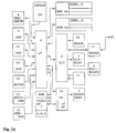
- FIG. 1a shows a block diagram of the franking machine according to the invention with a printer module 1 for a fully electronically generated franking image, with at least one input means 2 having a plurality of actuating elements, a display unit 3, a MODEM 23 establishing communication with a data center, which via an input / output control module 4 are coupled to a control device 6 and with at least one non-volatile memory 5a or 5b for the variable and a memory 10, 11 for the constant parts of the franking image.
- a character memory 9 supplies the necessary print data for a volatile working memory 7.
- the volatile working memory 7 comprises, for example, an external RAM in conjunction with an internal RAM 6b arranged in the processor.
- the control device 6 has a correspondingly designed microprocessor ⁇ P and is with the input / output control module 4, the character memory 9, the volatile working memory 7, with a non-volatile cost center memory NVM 5a and with a non-volatile working memory NVM 5b, with an application-specific program memory ASP 10 (Cliché EPROM), a program memory PSP 11 (Program EPROM), connected to the motor of a transport or feed device, possibly with a strip release 12, an encoder (coding disk) 13, a letter sensor 16 and a clock / date module 8.
- a corresponding method for controlling the printing of a postage stamp image in columns is described in more detail, for example, in EP 578 042 A2 or in EP 576 133 A2.
- the increased security according to the invention is achieved in connection with an E 2 PROM 20, which is located externally of the microprocessor housing. Both are permanently attached to the board.
- the control device 6 - shown in more detail in FIG. 2a - has a microprocessor or an OTP processor (ONE TIME PROGRAMMABLE).
- OTP also houses other circuits in a common component housing.
- These further circuits and / or programs or data in the internal OTP-ROM 6c or in the internal OTP-RAM 6b in the common processor housing form a security circuit or a first security means against unauthorized manipulation.
- the first non-volatile memory NVM 20 is, for example, an E 2 PROM and serves as a second security means against unauthorized manipulation.
- an external non-volatile memory NVM 25 forms a second security means against unauthorized manipulation and is connected to the processor 6 via an input / output control module 4 and is secured against removal during the running time of the franking machine.
- the remaining individual memories can be combined in a number of physically separate modules or in a few modules as shown in FIG. 2a be realized.
- the read-only memories CSP 9 and PSP 11 are preferably combined in an EPROM and the non-volatile memories NVM 5a and 5b to be protected are combined in a postal register memory.
- the latter is preferably duplicated and is redundantly written with data in its memory areas.
- a method for storing security-relevant data is described in more detail, for example, in EP 615 211 A1.
- FIG. 1b The block diagram of a franking machine shown in FIG. 1b achieves increased security according to the invention with an OTP-internal non-volatile memory (NVM), preferably an E 2 PROM 6d.
- NVM OTP-internal non-volatile memory
- the control device 6 - shown in more detail in FIG. 2b - has a microprocessor or an OTP processor (ONE TIME PROGRAMMABLE).
- OTP processor ONE TIME PROGRAMMABLE
- internal non-volatile memories NVM 6d and further circuits are accommodated in the OTP in a common component housing.
- the aforementioned internal non-volatile memory NVM 6d and further circuits and / or programs or data in the internal OTP-ROM 6c or internal OTP-RAM 6b in the common processor housing again form a security circuit or a security means against unauthorized manipulation.
- An internal non-volatile memory NVM 6d in the security means of the OTP processor (CPU) 6 works together with the program memory 6c (internal EPROM or ROM) and volatile data memory RAM 6b. Reading out the internal non-volatile memory can be prevented by the possibility of setting backup bits (with internal EPROM) or with mask programming during production (with internal ROM).
- the latter forms a second security means against unauthorized manipulation.
- the external non-volatile memory NVM 20 - as shown in FIG. 1a - is a component of the processor system of the franking machine and works together with the program memory 6c (internal EPROM or ROM) and volatile data memory RAM 6b.
- a chip card read / write unit 21 is also shown in the aforementioned block diagram of the franking machine 1 according to the invention. This is connected via a bus 11 to a processor 6 directly or via input / output means (I / O ports) 4. Furthermore, a connection of a MODEM 23 via the BUS 11 directly or via the aforementioned input / output means 4 is provided, which is not shown in more detail in FIG. 1a.
- the chip card which has to be inserted into the chip card read / write unit 21 includes an external non-volatile memory 25. Such a non-volatile memory can also be present in a similar system.
- security bits are set by programming the internal EPROM during the manufacture of the franking machine in the OTP processor. Observing such security-relevant routines, such as billing routines, with an emulator / debugger would also lead to a change in the timing, which can be determined by the OTP.
- This also includes a clock generator / counter circuit for the specification of time intervals or clock cycles, for example for time-out generation or printer control. The clock generator / counter circuit is advantageous for program runtime monitoring used, which is described in more detail in the application EP 660 269 A2.
- the clock / counter circuit When a certain time has elapsed and the expected event has not occurred, the clock / counter circuit generates an interrupt which reports to the microprocessor that the time has elapsed without success, whereupon the microprocessor initiates further measures.
- the monitoring function is carried out in the aforementioned manner by the aforementioned first security means, which is part of the processor (OTP) and which becomes effective in connection with appropriate software during the operation of the franking machine.
- OTP processor
- a code word in the external NVM 5a, 5b or 25 is deleted. This can be done by overwriting with a predetermined other word, for example 0000.
- the advantage is in particular that the safety circuit reacts to manipulation by unauthorized intervention in the franking machine during operation.
- the monitoring function is also carried out in the second variant - shown in FIGS. 1b and 2b - in the aforementioned manner, but now by the safety circuit formed by means 6a and 6d, which is part of the processor (OTP) and which is associated with corresponding software takes effect during the operation of the franking machine.
- a CMOS single-chip 8-bit microcontroller Philips 80C851 or 83C851 with a non-volatile 256x8-bit E 2 PROM can, for example, be used as the processor as internal processor memory.
- the code word can be stored in the above-mentioned internal processor memory more than 50,000 times in a non-volatile manner. Data retention is also guaranteed for 10 years.
- Another suitable processor is, for example, the TMS 370C010 from Texas Instruments, which also has an internal 256 byte E 2 PROM.
- the internal franking machine security circuit for postal register data and other security-relevant data protects the data content of non-volatile memories, for example CMOS-SRAMs supported by a lithium battery, against the use of illegally cloned copies without billing.
- the aforementioned lithium battery-supported CMOS SRAMs have a lifespan of at least 10 years.
- a non-volatile memory device is available from Dallas Semiconductor for the DS1230Y / AB, for example, a memory area of 256 K or a memory area of 1024 K for an NV-SRAM for the DS1245Y / AB.
- the clock / date module 8 can also be protected by the same method.
- This module is a non-volatile timer RAM and also contains a lithium battery for at least 10 years.
- the DS 1642 device from Dallas Semiconductor has a 2K x 8 NV-SRAM.
- the safety circuit stores in this non-volatile memory, for example, only data at the time the franking machine is switched on or restarted after a standby operation, that is to say at times when there is no billing requirement and no franking takes place.
- Normal E 2 PROM memories in particular of the 28256 type, do not require an internal battery and allow at least 10,000 to 100,000 read / write cycles.
- the internal postage meter security circuit for postal register data and other security-relevant data accordingly controls the aforementioned non-volatile memory modules so that the service life is increased or sufficient.
- the data content of the postal register as If the checksum is stored in encrypted form, manipulation of the postal register can be effectively prevented from the start.
- an OTP processor ONE TIME PROGRAMMABLE
- Set flags prevent the safety-relevant data from being read out of the processor.
- a known checksum method is based on a MAC (MESSAGE AUTHENTIFICATION CODE) which is attached to the data to be backed up. Such MAC protection is advantageously placed over the postal register data.
- the aforementioned code word which is changed at intervals in terms of time or quantity, can also be used for MAC protection of the postal register data.
- a stored code word is sufficient, which is changed at intervals to guarantee security.
- the monitoring function is also implemented in the processor in the first variant — shown in FIGS. 1a and 2a.
- an 8051 processor with a 16 kbyte on-chip EPROM can be used as internal program memory.
- the internal OTP-RAM has a memory area of 256 bytes.
- the non-volatile memories containing the postal register data in particular battery-backed CMOS-RAMs (Bat-NV-CMOS-RAMs), contain a code word which corresponds to the last operating state of the franking machine before switching off or power failure or before a certain downtime (status by) or before the program was interrupted and that the old code word is replaced by a predetermined new code word at least when the franking machine is switched on.
- Battery-backed CMOS-RAMs Bat-NV-CMOS-RAMs
- the code word thus becomes predetermined Events automatically changed by the operational franking machine in all non-volatile memories that deal with security-relevant data.
- Such a measure prevents a cloned memory content of a non-volatile memory (Bat-NV-CMOS-RAM's) from being used more than once because the code word in the non-volatile internal processor memory and in the post register (Bat-NV-CMOS-RAM's) is changed, as soon as a predetermined operating state of the franking machine is reached after switching on the machine or after voltage recovery after a failure, after leaving the communication mode or after reloading the franking machine with a credit or after a certain downtime (stand by) or after another program interruption.
- the above Measure does not prevent duplication or cloning of a Bat-NV-CMOS-RAM or other NVRAM's.
- a duplicate of the memory content, which is exchanged for the memory content of the original, can also be used.
- the original's code word becomes invalid later, i.e. a replacement of the memory contents would be noticed by the processor due to the code word in the non-volatile internal processor memory, which has meanwhile also been changed.
- the code words cannot be changed by the manipulator without knowledge of the key and the parameter data, even if the data content of the memory has remained the same, if the algorithm for forming the new code word were known.
- a known encryption method such as DES, can therefore be used.
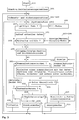
- the method for increasing the security against manipulation of critical register data comprises further security steps, which are shown in FIG.
- step 106 the code words stored in the non-volatile memories to be protected are read in succession and then transmitted to the processor.
- the processor carries out a security step 107 for checking the previously valid code word and a step 108 for correspondingly changing the code word if the check has shown the correspondence or absence of errors. Otherwise, a branch is made from step 107 to step 109 in order to set a number characterizing the kill mode or at least a MAC-secured kill mode flag in the permanently installed non-volatile external security memory.
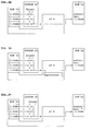
- FIGS. 8a to c show pointer positions according to the method according to the invention.
- FIG. 8a shows an initial state presetting. Such a step is required in step 107 (FIG. 7) in order to determine the correct old code word from the stored list.
- the pointer stands on a number 1.
- the serial number of the franking machine can also form a starting number.
- the pointer position (number 1 or starting number) is saved.
- a corresponding first code which is at a first position in the list, is then stored in the NVM 5a or 5b to be protected.
- the franking machine leaves the manufacturing plant with a number 1 or initial number.
- the franking machine is now switched on or switched on again (FIG. 8b).
- the first code is read from the list in accordance with the pointer position and compared with the first code stored in the NVM 5a or 5b to be protected.
- This first phase corresponds to step 107 of FIG. 7, in which it is determined whether a memory has been removed in the meantime without billing and has been replaced by another and has now been used again with old data. If the codes are the same, the FIG. 8 c, the pointer position is forwarded to a second code word in the list, which can be gathered from step 108 in FIG. 7.
- the pointer position is changed in a predetermined manner. In the simplest case, the pointer position is incremented or decremented.
- the first code in the NVM 5a or 5b to be protected is now replaced by the second code, ie overwritten. If the postage meter machine is now switched on or switched on again after switching off, a check is carried out on the basis of the current code in a manner analogous to that shown in FIGS. 8b and 7, step 107.
- a count value is incremented in the internal NVM 20 before a new code word (W ', T', U ', V') is formed.
- a cryptographic function can be used as the mathematical function F, which is stored in the internal OTP-ROM as an algorithm or program.
- the DES algorithm Data Encryption Standard
- a random function can be used, for example to determine the new pointer in accordance with F.
- code words comprises the calculation and / or selection from a list of code words which is stored in the internal OTP-ROM. Ideally, each code word should only be used once to protect the external non-volatile read / write memory. However, this requires a large number of code words, which are stored in the internal OTP-ROM.
- a code word stored in the list can be read out in encrypted form if a special processor is present.
- the code words from the memory to be protected and the code word from the aforementioned list, to which the pointer points, are encrypted and transmitted to the chip card, which also has a processor which can also carry out a comparison for the purpose of security checking.
- the code word is transmitted from the franking machine to the memory of a remote similar processor system. Every time the franking machine is switched on, a connection is made to the memory of the remote similar processor system. The absence of errors is determined by comparing the code word stored externally in the remote similar processor system with the code word stored in the post register NVRAM, in order then to form a new code word and to store it in the NVRAM of the remote similar processor system and in the post register NVRAM. The comparison of the unique code words is carried out in the franking machine.
- An expedient variant consists in storing the unique code word formed according to an algorithm in a more specific transmission medium (e.g. chip card).
- a communication connection to the remote similar processor system would then not be a prerequisite for commissioning the franking machine if the chip card was inserted at the beginning, which is also the last time, i.e. was inserted in previous frankings.
- a corresponding communication mode 300 is of course provided after switching on during the running time of the postage meter machine.
- step 106 the code words stored in the non-volatile memories to be protected are read in succession and then transmitted to the processor.
- the processor carries out a security step 107 for checking the previously valid code word and a step 108 for correspondingly changing the code word if the check has shown the correspondence or absence of errors. Otherwise, a branch is made from step 107 to step 109 in order to delete a code word Y or to set at least one kill mode flag in the non-volatile memory 6d in the processor.
- a new code word is generated again with internal data and according to an internal program by means of such a mathematical function F, which makes the external replication of code words considerably more difficult, so that manipulation with the intention of forgery is made practically impossible.
- the inclusion of postal register values as a test characteristic value and gluing or secure encapsulation of at least one of the external non-volatile read / write memories can be dispensed with. Only later, for example in franking mode 400 (FIG. 5), is the data content checked during billing whether the register value sum R3 is equal to the sum of ascending register R1 (residual value) and descending register R2 and / or whether the postal register values are valid (e.g. through authenticity checks, plausibility checks and similar checks).
- the method according to the invention is integrated in an overall flow chart of the franking machine, shown in FIG. 3. After the start 100, measures for the security check and for restoring a defined initial state are carried out in a step 101 comprising the start routine and initialization.
- the further steps 102 to 105 optionally take place to restore operational readiness, for example after the franking machine has been repaired, and are shown in more detail in FIG.
- Step 106 to 109 the read old ones Checked code words and exchanged for new code words.
- the new code word is then also transferred to the NV-RAMs NVM 5a and NVM 5b, where it forms a corresponding code word (V ', U').
- Step 108 also includes checking that the code words (U ', V' or W ', T') have been correctly stored. If an implausible deviation is found when checking the previously valid code word, a branch is made to a step 109 which includes measures which ultimately prevent further franking with the franking machine. For example, a third code word Y specified by a data center can be deleted, the absence of which proves the manipulation. The system routine (point s) is then followed.
- the overall flowchart for the franking machine shown in FIG. 3 has steps 201 to 206 and 207 to 208 for monitoring further criteria. If, for example, a security criterion checked in step 207 is violated, the franking machine enters a corresponding kill mode (step 208). The franking machine enters a sleeping (warning) mode (203-206) based on a security criterion checked in step 202 , if a connection to the data center has not yet been established after the consumption of a predetermined number of pieces.
- the franking machine and the data center each agree on a predetermined number of items S, ie the amount that can be franked until the next connection is established. If communication fails (quantity control), the franking machine slows down its mode of operation (sleeping mode variant 1) so that work can continue without a warning being displayed up to the next quantity limit. However, it is possible to issue a renewed warning at ever shorter intervals, ie after a predetermined number of frankings, which is more and more urgent draws attention to the need for communication with the data center (sleeping mode variant 2).
- step 203 comprises a sub-step for error statistics in accordance with the statistics and error evaluation mode 213.
- This variant does not require the aforementioned step 204.
- Franking is not affected by Sleeping Mode. As long as the check in step 205 shows that the number of pieces S is even greater than zero, step 207 is reached. Only the warning appears more and more on the display. Otherwise, a branch is made to step 206, for example setting a FLAG, which is queried later in step 301 and evaluated as a communication request.
- step 206 an additional indication can also be given that communication is now taking place automatically and as long as the franking function is at rest until communication is successfully completed.
- the franking machine user can call up the communication mode 300 at any time beforehand.
- step 207 preceding communication mode 300, further criteria relevant to security against manipulation are checked. If the machine is tampered with and has been tampered with, it is directed to step 208 in order to prevent franking with the tampered with machine. In such a case, the machine would enter kill mode. If the franking machine is only in sleeping mode, franking is not prevented.
- step 207 After checking the criteria for the kill mode (steps 207 to 208) and for the sleeping mode (steps 202 to 206), one shown in FIG Point t reached.
- step 209 entries can be made before point e is reached.
- step 211 If the communication was successful, a query is made in step 211 as to whether data have been transmitted. Step 213 is then reached. In step 213, the current data are determined or loaded, which are called in step 201 and then required again for the comparison in step 202.
- the transmitted decision criterion is preferably the new number S '.
- the evaluation mode in step 213 also includes the formation of new code words U ', V' for the non-volatile memories to be protected as a result of a reloading process which was carried out in communication with a data center.
- Steps 106 to 109 shown by way of example in FIG. 7 for code word Y also run analogously for code words U ', V'.
- a new third code word Y 'specified by the data center is loaded, which can replace the old third code word Y.
- opening the franking machine and replacing defective components may be unavoidable. For this reason, previous measures to obtain authorization to intervene are required, which allow the franking machine to be operated after it has been repaired. An unauthorized opening of the franking machine is excluded. If the Postage meter machine is put into operation again after the intervention, because of the authorization to intervene for the postage meter machine, that new third code word Y 'specified by a data center can replace the old third code word Y, as was proposed, for example, in the application DE 43 44 476 A1.
- the franking machine could continue to be operated.
- the franking machine can continue to be operated because a new third code word Y 'is used, branching to step 108, as shown in FIG. 7, in order to form a new changeable code word (T', W ') and as Load code word (V ', U') into the NV-RAMs.
- the complementary shadow (V '', U '') can be used in at least one of the memory areas or NVRAMs are worked on.
- the form of checking the previously valid code words and replacing them with new code words in one of the memory areas of the non-volatile memory NVM 5a, 5b also changes in accordance with steps 102 to 105 shown in FIGS.
- the new code words V ', U' and / or Y 'stored in a memory area E of the NVM 5a, 5b are deleted and the new code words are appropriately addressed so that they can be called up.
- This can advantageously be done analogously to the sequence - as shown in FIG. 7 in DE 43 44 476 A1 - in that the new code words V ', U' and / or Y 'refer to the address of the old code words V, U and / or Y can be set.
- a point p is reached and, according to the details of the flowchart shown in FIG. 4, a first saving step 106 of the flowchart of the method according to the invention shown in FIG. 7 is carried out via steps 102 to 105 reached.
- Step 101 shown in FIG. 3 comprises several sub-steps, which are explained in more detail below with reference to FIG. 4.
- step 1010 The usual hardware and display initialization routines first run in step 1010 before a step 1011 for timer and interrupt start is reached.
- the internal program then starts with security checks.
- security checks it can already be checked here in step 1020 whether a code word or memory content is valid. Then, if valid, step 1040 is reached for the automatic input of stored data with print data preparation and embedding of the image data.
- a further step 1052 tests whether the program module has to be processed further. If this is not the case, the next program module PM (+1) is called in step 1054. Otherwise, it is checked in a step 1053 whether program sections of a previous program module PM (-1) have to be finished and branches to a step 1056 or a step 1055 if a program section of the current program module PM must be processed further. After determining the current program module in accordance with steps 1054, 1055 or 1056, a branch is made to point p.
- markers for example a phase identifier, as is known from DE 42 17 830 A1, or pointers are set which, after a power failure and being switched on again, enable defined states to be reconstructed for further program execution.
- point s and thus system routine 200 are reached.
- the point s is reached after the steps for a test mode 216, for a display mode 215 and for a franking mode 400 have been carried out.
- the invention is based on the fact that after switching on, the postage value in the value print corresponding to the last entry before switching off the franking machine and the date in the day stamp corresponding to the current date are automatically specified that the variable data in the fixed data for the frame for the print and are electronically embedded for all associated data that remain unchanged (FIG. 4, step 1040).
- the time in the battery-supported clock / date module 8 continues to run even when the franking machine is switched off and is constantly stored at least as a date and in step 1040 of FIG. 4 in the initialization routine 101 embedded.
- step 401 is reached in franking mode 400 after the franking machine has been switched on, after the system routine 200 has been carried out and during the operating mode, data that has already been stored can be accessed without input.
- This setting relates in particular to the last setting of the postage meter with regard to the postage value, which is displayed in step 209, before a new entry, display and print data preparation is carried out, if necessary.
- the current variable pixel image data (date and postage value) are embedded in the fixed frame pixel image data.
- step 401 the input means are queried for any further inputs. If there are further entries, a loop counter is reset in step 403 and branched back to point t (FIG. 3).
- the input data which are entered with a keyboard 2 or via an electronic scale 22 connected to the input / output device 4 and calculating the postage value, are automatically stored in the memory area D of the non-volatile working memory NVM 5.
- data records of the sub memory areas for example B j , C etc., are also stored in a non-volatile manner. This ensures that the last input values are retained even when the franking machine is switched off, so that after switching on the postage value in the value print is automatically specified in accordance with the last entry before the franking machine was switched off and the date in the day stamp is specified in accordance with the current date.
- step 209 the possible entry of new values is queried. If, for example, no new postage value has been entered, then the previous postage value stored in the memory area is used and point e (FIG. 3) is reached in order to query further entries before the franking mode 400 (FIG. 5). is achieved.
- step 401 If a new input request is found in step 401, the process branches back to step 209 via step 403. Otherwise, branch to step 402 to increment the loop counter. Via step 404, in which the number of loops passed through is checked, step 405 is reached in order to wait for the print output request. A letter that is to be franked is detected by a letter sensor. This generates a signal for the print output request.
- step 405 the print output request is awaited, in order to then branch via steps 407, 409 and 410 to the billing and printing routine in step 406. If there is no print output request (step 405), the process branches back to step 209 (point t) and, if there is no communication request, via steps 211, 212 and 214 to step 401 of franking mode 400, according to the overall flow chart shown in FIG. 3.
- a communication request can be made at any time by manual input or another input can be made in accordance with the steps test request 212 and register check 214.
- Step 401 is reached again. If no input request is recognized, further steps 402 and 404 - as shown in FIG. 5 - are carried out.
- a further query criterion can be queried in a step 404 in order to set a standby flag in step 408 if, after a number of loops that have been run through, no input has been made and no print output request has been made.
- the standby mode is also reached when a letter sensor 16 known per se - shown in FIG. 1a - does not determine a next envelope in a predetermined time which is to be franked.
- Step 404 - shown in FIG. 4 - in franking mode 400 either comprises a query for a timeout or for the number of passes through the program loop, which ultimately leads back to the input routine in accordance with step 401. If the query criterion is met, a standby flag is set in step 408 and the system routine 200 branches back directly to point p or alternatively to point s without the billing and printing routine being executed in step 406. When branching to point p, an additional change of the code words can be achieved during the standby mode. In the case of a variant (not shown in FIG. 5) with a branching to point s, however, only a change in the code words can only be achieved after switching on.
- the standby flag is queried during the system routine 200 in step 211 and, if necessary, is reset after the checksum check in step 213 if no attempted manipulation is detected.
- the query criterion in step 211 is expanded to include the question of whether the standby flag is set, ie whether the standby mode has been reached. In this case, a branch is made to step 213.
- a preferred variant with manipulation monitoring during the standby mode is to delete a code word Y in the manner already described if a manipulation attempt in the standby mode has been determined in step 213 in the aforementioned manner. The absence of code word Y is recognized in step 207 and then branched to step 208.
- the advantage of this method in connection with the first mode is in that the manipulation attempt is statistically recorded in step 213.
- the standby flag can thus be queried in step 211 following communication mode 300. This does not branch to franking mode 400 until the checksum check has shown that all or at least some selected security-relevant programs are complete and valid.
- step 405 If a print output request is recognized in step 405, further queries are made in subsequent steps 409 and 410 and in step 406. For example, in step 407 a check of the register values and additionally the code word Y can be carried out and in step 409 the validity and additionally the presence of a kill mode flag set in step 208 (FIG. 3) is determined in order to proceed to step 410 branch. Otherwise, a branch is made to step 413 for statistical and / or error evaluation and step 415 for displaying the error if the register values were not authentic.
- step 410 the achievement of a further quantity criterion is queried.
- the system automatically branches to point e in order to enter communication mode 300 so that a new predetermined number of pieces S is again credited by the data center.
- the process branches from step 410 to steps 4060, 4061 or 4062 and 4063 to the billing and printing routine in step 406.
- a pseudo-random sequence is displayed during the operation of the franking machine before each print and thus before each new number of items to be registered Franking imprints generate a random number based on the previous number of items and, if applicable, the current time supplied by the clock / date module.
- a pseudo-random generator is provided with appropriate hardware (not shown) or with a program stored in the internal OPT-ROM of the OTP processor. At least one of the large number of possible random words that can be generated is stored in the internal OPT-ROM of the OTP processor.
- step 4061 After a comparison in step 4061 and a subsequent authenticity check of the MAC in step 4062 within the OTP processor, if there is a match, redundant storage of the new code word is stuck once in the releasable non-volatile memory (NVRAMs) and, according to the invention, in the aforementioned non-releasably firmly on the circuit board non-volatile memory (E 2 PROM) 20 or in the internal OTP-NVM 6d or in the external memory 25.
- E 2 PROM circuit board non-volatile memory
- step 4061 a large number of stored further conditions can also be queried, when they result in the result that a new code word is stored in a non-volatile memory 20, 25 or in the internal OTP memory 6d.
- E 2 PROM can be used.
- the permissible number of read / write cycles for an E 2 PROM is not exceeded if, for example, the average non-volatile memory (E 2 PROM and NVRAMs) is only redundantly written with a new code word every twenty-fourth franking.
- MAC MAC
- the accounting data in the non-volatile memories to be protected 5a and 5b with reference to the appended MAC usually 'checked s.
- step 4061 event is in - shown unspecified - sub-steps of the step 4062 of the accounting data set in the OTP transmitted 6, to check it on the basis of that MAC's or codeword, which in - as the second locking means to prevent unauthorized manipulation serving - non-volatile memory is stored.
- the accounting data record is encrypted to a MAC using the code word.
- the MAC formed in this way is compared with the MAC attached to the accounting data record in the non-volatile memory 5a and 5b to be protected. The comparison can also be made in a crosswise comparison. If the MAC ' Is is authentic, a branch is made to step 4063.
- step 4063 provision is made to at least prepare both the formation of the new code word and the storage of billing data before branching to the billing and printing routine in step 406. In the event of an established error or if the MACs do not match, step 4062 branches back to step 413 for statistical and error evaluation.
- step 4060 if in step 4060 a non-matching pseudo-random number Z is generated during operation of the franking machine before each footprint, that is, a pseudo-random number Z, which in the comparison in step 4061 a mismatch with the at least one internal OPT-ROM of the OTP processor stored stored random number Z should result, then branching to the accounting and printing routine in step 406 without forming a new code word. The MAC formation then takes place using the previously valid code word.
- the invention avoids that if the postal registers and their contents are removed without authorization in order to make any number of copies, that mail items can then be franked without billing at the data center or payment at the post office if cloned memory contents are used. It is not necessary to encapsulate the NVRAM components for the postal register with a security housing. If a potential manipulator, for example from the 1st to the 23rd franking, works with cloned memories (battery-backed CMOS RAMs), this can be determined automatically by means of a self-check by the franking machine if a code word has been changed in between.
- the data contained in the postal register - in particular in the battery-backed CMOS NVRAMs - determined in accordance with a random or pseudo-random sequence number of frankings also stored non-volatile in the E 2 PROM 20, 25 or in the internal OTP memory 6d will.
- a code is checked by the processor (in step 4062, Fig. 5) before each (in ⁇ approximately after the 24th posting) in the E 2 PROM and which for each new storage in the E 2 PROM is changed (in step 4063, Fig. 5).
- This check code is stored in a kth register of the NVRAMs and can at the same time form a checksum, for example a MAC protection for the register values.
- the checksum or MAC protection for the register values is done by changing and for NVRAM and E 2 PROM different algorithms and keys are formed, which are stored in an OTP-ROM of an OTP processor. Copying the E 2 PROM memory content to the NVRAM is therefore pointless if different test codes protect different memories with related or related memory contents.
- each individual register value can be stored encrypted in the E 2 PROM.
- An advantage of the invention is, however, that this does not have to be done with every settlement. Nor does each individual register value have to be stored redundantly in the E 2 PROM. A potential manipulator cannot restore the data to a row in the table itself. Which keys and algorithms are used where is listed in the OTP-ROM.
- a pointer whose data is encrypted or stored in a MAC-secured manner in the E 2 PROM, points to corresponding positions in the list in the OTP-ROM (see Fig. 8).
- a counter can be decremented or incremented to form the pointer.
- step 4061 If a pseudorandom number has been reached (in step 4061, FIG. 5) and the check of the MACs by the NVRAM and by the E 2 PROM has shown that the data is authentic, in a preferred variant, billing is carried out and a CRC checksum is formed for all the register values at the point in time immediately before franking or before step 406 for the customary billing and printing routine and stored differently coded for NVRAM in the E 2 PROM (in step 4063, Fig. 5). If the process then branches to step 406, (FIG. 5), only the printing routine needs to be carried out, as is carried out, for example, in EP 576 113 A2, in step 49 of FIG. Otherwise, step 4061 branches directly to the normal billing and printing routine (in step 406, FIG. 5) and billing is carried out in step 406 before printing takes place.
- the solution according to the invention is based on an expansion security of the processor with internal or external E 2 PROM with a permanent E 2 PROM attachment on the processor circuit board.
- a random number is generated on the basis of the previous number of pieces and, if applicable, the current time supplied by the clock / date module.
- Such electronic counters can also be implemented by means of the battery-supported clock / date module 8.
- the clock / date module cannot be set to a previous date before the current date.
- the running time is measured and entered into a random algorithm to form a number. If a predetermined number is reached, redundant storage in the E 2 PROM and NVRAM is carried out in the above-mentioned manner in a correspondingly secure manner during the next franking.
- a pseudo-random algorithm is generated in terms of hardware by means of a bit pattern generator.
- This is an n-fold shift register with special feedback, which can preferably be part of an ASIC.
- the E 2 PROM and processor can be implemented with at least their safety-relevant parts.
- the pseudo-random algorithm results in an average value of approx. 24 frankings, in which the data is saved redundantly.
- a non-volatile memory in the OTP or (expanded) E 2 PROM arranged securely to the OTP is advantageously assumed in order to guarantee the security against manipulation with respect to cloned memory contents.
- storage is not only dependent on specific times, such as when switching on and / or transition to standby mode, in order to ensure manipulation security with respect to cloned memory contents (branching to point p, FIG. 3), but the aforementioned time is now randomly granted.
- the time of saving can thus no longer be logically derived or foreseen by a potential counterfeiter, but can only be determined retrospectively in relation to the number of pieces.
- step 406 the content of the register data which has been used for billing in a known manner is checked and changed accordingly. For example, with a valid franking with a value> 0, the piece counter R4 is incremented. The register value R1 is reduced and the register value R2 is increased accordingly, so that the register value R3 remains constant. A checksum (for example CRC) is then formed over each of the register values and stored in the NVM 5a and / or NVM 5b together with the associated register values.
- CRC checksum
- the MAC Message Authentication Code
- the MAC is an encrypted checksum which is appended to the register value when billed in step 406 (FIG. 4).
- DES encryption is suitable, for example.
- the data content can additionally be checked during billing whether the register value sum R3 is equal to the sum of the ascending register R1 (residual value) and descending register R2. Due to the security with the encrypted checksums, a content check can be completely dispensed with, especially since the data center carries out this every time the franking machine communicates. If all columns of a print image have been printed, the system branches back to the system routine 200.
- the non-volatile memories (E 2 PROM and NVRAMs) are also redundantly written with a new code word in another last operating state of the postage meter machine. Such another last operating state is assigned to predetermined states, as described above.
- the number of printed letters and the current values in the mail registers are registered in accordance with the entered cost center in the non-volatile memory 5a of the franking machine during the accounting routine 406 and are available for later evaluation.
- a special sleeping mode counter is caused to continue counting during the accounting routine which takes place immediately before printing. If required, the register values can be queried in display mode 215 (FIG. 3). This then branches back to the system routine 200.
- the TMS370 C010 from the Texas Instrument processor family is suitable for the postage meter internal safety circuit. This has an internal E 2 PROM of 256 bytes as NVM.
- the non-volatile internal processor memory and the non-volatile postal register memory (Bat-NV-CMOS-RAM's) to be protected do not contain the identical, but one of the two the complementary code word.
- the processor-internal code word cannot be queried from the outside.
- different code words are assigned to individual memories, the different code words, however, having a common stem from which they were formed and the common stem being reconstructed by the processor in order to check the validity of the individual code words.
- the routine for the code word comparison or for the validity check is queried in the processor each time it is switched on or when the program is continued. If a discrepancy is found in the comparison, the franking machine is blocked for further operation.
- the number of new code words formed is counted from a predetermined point in time and is stored in the non-volatile memory in the processor. At the time of communication with the data center, the aforementioned number of code words formed in the past and the currently valid code word are queried. If the franking machine is blocked unintentionally due to invalid code words, this then enables the old state to be restored afterwards by appropriate data transmission from the data center to the franking machine.
- a last operating state of the franking machine corresponding to the code word is a state as a result of the manufacture or reloading of the franking machine or a state before the franking machine is switched off or a state before a voltage failure or before a standstill (stand by) or before a program interruption includes.
- Such last operating states can also occur when monitoring further criteria, in that the franking machine switches to a corresponding mode.
- the overall flow chart for the franking machine shown in FIG. 3 has such steps 202 and 207 for monitoring further criteria. If one of the security criteria is violated, the franking machine enters a corresponding mode and additionally executes steps 106 to 109 according to the invention - shown in FIG. 7 - in corresponding subroutines.
- the franking machine enters a sleeping mode, for example, if a connection to the data center has not yet been established after a predetermined number of pieces has been consumed, and if communication is not triggered manually by the user, there is automatic communication with the data center and one if the number of pieces credit is exhausted Implementation of the procedure to increase the security against manipulation of critical register data.
Landscapes
- Physics & Mathematics (AREA)
- Engineering & Computer Science (AREA)
- Mathematical Physics (AREA)
- Theoretical Computer Science (AREA)
- General Physics & Mathematics (AREA)
- Devices For Checking Fares Or Tickets At Control Points (AREA)
- Techniques For Improving Reliability Of Storages (AREA)
Applications Claiming Priority (4)
| Application Number | Priority Date | Filing Date | Title |
|---|---|---|---|
| DE19534527 | 1995-09-08 | ||
| DE1995134527 DE19534527C2 (de) | 1995-09-08 | 1995-09-08 | Verfahren zur Erhöhung der Manipulationssicherheit von kritischen Daten |
| DE19534529 | 1995-09-08 | ||
| DE1995134529 DE19534529C2 (de) | 1995-09-08 | 1995-09-08 | Verfahren zur Erhöhung der Manipulationssicherheit von kritischen Daten |
Publications (2)
| Publication Number | Publication Date |
|---|---|
| EP0762337A2 true EP0762337A2 (fr) | 1997-03-12 |
| EP0762337A3 EP0762337A3 (fr) | 2000-01-19 |
Family
ID=26018690
Family Applications (1)
| Application Number | Title | Priority Date | Filing Date |
|---|---|---|---|
| EP96250191A Withdrawn EP0762337A3 (fr) | 1995-09-08 | 1996-09-06 | Procédé et dispositif pour augmenter la protection contre la manipulation de données critiques |
Country Status (2)
| Country | Link |
|---|---|
| US (1) | US5771348A (fr) |
| EP (1) | EP0762337A3 (fr) |
Cited By (2)
| Publication number | Priority date | Publication date | Assignee | Title |
|---|---|---|---|---|
| FR2758033A1 (fr) * | 1996-12-31 | 1998-07-03 | Motorola Inc | Dispositif et procede de protection d'information electronique dans un dispositif de communication sans fil |
| EP1811460A1 (fr) * | 2005-12-22 | 2007-07-25 | Pitney Bowes, Inc. | Système logiciel sécurisé et procédé pour une imprimante |
Families Citing this family (46)
| Publication number | Priority date | Publication date | Assignee | Title |
|---|---|---|---|---|
| WO1998024021A1 (fr) * | 1996-11-29 | 1998-06-04 | Hitachi, Ltd. | Systeme de commande de micro-ordinateur |
| DE19810730A1 (de) * | 1998-03-12 | 1999-09-16 | Philips Patentverwaltung | Microcontrollerschaltung |
| US7028014B1 (en) * | 1998-03-18 | 2006-04-11 | Ascom Hasler Mailing Systems | Tamper resistant postal security device with long battery life |
| FR2786285B1 (fr) * | 1998-11-24 | 2001-02-02 | Secap | Dispositif et procede de protection contre le debordement de pile dans une memoire et machine a affranchir les mettant en oeuvre |
| FR2786286B1 (fr) * | 1998-11-24 | 2001-08-31 | Secap | Dispositif et procede de detection de debordement de pile dans une memoire et machine a affranchir les mettant en oeuvre |
| FR2787899A1 (fr) * | 1998-12-29 | 2000-06-30 | Secap | Dispositif et procede de protection de donnees sensibles et machine a affranchir les mettant en oeuvre |
| DE19958941B4 (de) | 1999-11-26 | 2006-11-09 | Francotyp-Postalia Gmbh | Verfahren zum Schutz eines Gerätes vor einem Betreiben mit unzulässigem Verbrauchsmaterial |
| DE19958948B4 (de) | 1999-11-26 | 2005-06-02 | Francotyp-Postalia Ag & Co. Kg | Verfahren zur Bestimmung der Anzahl von mit einer Tintenrestmenge ausführbaren Drucken und Vorrichtung zur Durchführung des Verfahrens |
| US6862683B1 (en) | 2000-03-24 | 2005-03-01 | Novell, Inc. | Method and system for protecting native libraries |
| US20040073617A1 (en) | 2000-06-19 | 2004-04-15 | Milliken Walter Clark | Hash-based systems and methods for detecting and preventing transmission of unwanted e-mail |
| DE10136608B4 (de) * | 2001-07-16 | 2005-12-08 | Francotyp-Postalia Ag & Co. Kg | Verfahren und System zur Echtzeitaufzeichnung mit Sicherheitsmodul |
| US8578480B2 (en) | 2002-03-08 | 2013-11-05 | Mcafee, Inc. | Systems and methods for identifying potentially malicious messages |
| US8561167B2 (en) | 2002-03-08 | 2013-10-15 | Mcafee, Inc. | Web reputation scoring |
| US7693947B2 (en) | 2002-03-08 | 2010-04-06 | Mcafee, Inc. | Systems and methods for graphically displaying messaging traffic |
| US20060015942A1 (en) | 2002-03-08 | 2006-01-19 | Ciphertrust, Inc. | Systems and methods for classification of messaging entities |
| US7903549B2 (en) | 2002-03-08 | 2011-03-08 | Secure Computing Corporation | Content-based policy compliance systems and methods |
| US7458098B2 (en) | 2002-03-08 | 2008-11-25 | Secure Computing Corporation | Systems and methods for enhancing electronic communication security |
| US7694128B2 (en) | 2002-03-08 | 2010-04-06 | Mcafee, Inc. | Systems and methods for secure communication delivery |
| US8132250B2 (en) | 2002-03-08 | 2012-03-06 | Mcafee, Inc. | Message profiling systems and methods |
| US7870203B2 (en) | 2002-03-08 | 2011-01-11 | Mcafee, Inc. | Methods and systems for exposing messaging reputation to an end user |
| US6941467B2 (en) | 2002-03-08 | 2005-09-06 | Ciphertrust, Inc. | Systems and methods for adaptive message interrogation through multiple queues |
| US7124438B2 (en) | 2002-03-08 | 2006-10-17 | Ciphertrust, Inc. | Systems and methods for anomaly detection in patterns of monitored communications |
| US20030172291A1 (en) | 2002-03-08 | 2003-09-11 | Paul Judge | Systems and methods for automated whitelisting in monitored communications |
| US7302020B2 (en) * | 2002-05-20 | 2007-11-27 | Hewlett-Packard Development Company, L.P. | Encoded multi-access bus system and method |
| US20040112950A1 (en) * | 2002-12-12 | 2004-06-17 | Manduley Flavio M. | Secure stamp system |
| DE20318751U1 (de) * | 2003-12-04 | 2004-02-26 | Francotyp-Postalia Ag & Co. Kg | Einrichtung zum automatischen Ermitteln einer Produktbeschreibung zur Anzeige mittels einem Postverarbeitungsgerät |
| US8635690B2 (en) | 2004-11-05 | 2014-01-21 | Mcafee, Inc. | Reputation based message processing |
| CN100505796C (zh) * | 2004-11-24 | 2009-06-24 | 中兴通讯股份有限公司 | 一种手机显示时间的方法 |
| US7890721B2 (en) * | 2005-02-16 | 2011-02-15 | Atmel Corporation | Implementation of integrated status of a protection register word in a protection register array |
| US7937480B2 (en) | 2005-06-02 | 2011-05-03 | Mcafee, Inc. | Aggregation of reputation data |
| TWI303038B (en) * | 2005-11-15 | 2008-11-11 | Asustek Comp Inc | Computer dada security method, system |
| US8572399B2 (en) * | 2006-10-06 | 2013-10-29 | Broadcom Corporation | Method and system for two-stage security code reprogramming |
| US8214497B2 (en) | 2007-01-24 | 2012-07-03 | Mcafee, Inc. | Multi-dimensional reputation scoring |
| US7779156B2 (en) | 2007-01-24 | 2010-08-17 | Mcafee, Inc. | Reputation based load balancing |
| US8763114B2 (en) | 2007-01-24 | 2014-06-24 | Mcafee, Inc. | Detecting image spam |
| US7949716B2 (en) | 2007-01-24 | 2011-05-24 | Mcafee, Inc. | Correlation and analysis of entity attributes |
| US8179798B2 (en) | 2007-01-24 | 2012-05-15 | Mcafee, Inc. | Reputation based connection throttling |
| US8185930B2 (en) | 2007-11-06 | 2012-05-22 | Mcafee, Inc. | Adjusting filter or classification control settings |
| US8045458B2 (en) | 2007-11-08 | 2011-10-25 | Mcafee, Inc. | Prioritizing network traffic |
| US8160975B2 (en) | 2008-01-25 | 2012-04-17 | Mcafee, Inc. | Granular support vector machine with random granularity |
| US8589503B2 (en) | 2008-04-04 | 2013-11-19 | Mcafee, Inc. | Prioritizing network traffic |
| US20100145882A1 (en) * | 2008-12-10 | 2010-06-10 | Pitney Bowes Inc. | Method and system for securely transferring the personality of a postal meter at a non-secure location |
| US8621638B2 (en) | 2010-05-14 | 2013-12-31 | Mcafee, Inc. | Systems and methods for classification of messaging entities |
| US9471812B2 (en) | 2012-03-06 | 2016-10-18 | Freescale Semiconductor, Inc. | Method for implementing security of non-volatile memory |
| US9927990B2 (en) * | 2015-09-10 | 2018-03-27 | Toshiba Memory Corporation | Memory system, memory controller and memory control method |
| EP3373178B1 (fr) | 2017-03-08 | 2024-09-18 | Secure-IC SAS | Comparaison de signatures de données de contexte d'exécution avec des références |
Family Cites Families (29)
| Publication number | Priority date | Publication date | Assignee | Title |
|---|---|---|---|---|
| JPS594054B2 (ja) * | 1979-04-17 | 1984-01-27 | 株式会社日立製作所 | マルチプロセツサ障害検出方式 |
| US4447890A (en) * | 1980-07-14 | 1984-05-08 | Pitney Bowes Inc. | Remote postage meter systems having variable user authorization code |
| US4486853A (en) * | 1981-04-01 | 1984-12-04 | Telemet American, Inc. | Apparatus for receiving and displaying continuously updated data |
| EP0231452B2 (fr) * | 1982-01-29 | 2002-01-16 | Pitney Bowes Inc. | Systèmes à microprocesseur pour dispositif d'affranchissement électronique |
| DE3316414A1 (de) * | 1982-05-12 | 1983-12-22 | Bally Manufacturing Corp., 60618 Chicago, Ill. | Geraet und verfahren zum sicherstellen der unversertheit eines spielgeraets |
| US4606003A (en) * | 1982-09-30 | 1986-08-12 | Pitney Bowes Inc. | Mailing system peripheral interface with replaceable prom for accessing memories |
| JPS59192740U (ja) * | 1983-06-02 | 1984-12-21 | パイオニア株式会社 | コンピユ−タ装置 |
| DE3685191D1 (de) * | 1985-10-16 | 1992-06-11 | Pitney Bowes Inc | Systeme zur nichtfluechtigen speicherung von daten und frankiermaschinensysteme. |
| US4907150A (en) * | 1986-01-17 | 1990-03-06 | International Business Machines Corporation | Apparatus and method for suspending and resuming software applications on a computer |
| JPH0754536B2 (ja) * | 1986-02-17 | 1995-06-07 | 株式会社日立製作所 | Icカ−ド利用システム |
| US4858138A (en) * | 1986-09-02 | 1989-08-15 | Pitney Bowes, Inc. | Secure vault having electronic indicia for a value printing system |
| GB8704883D0 (en) * | 1987-03-03 | 1987-04-08 | Hewlett Packard Co | Secure information storage |
| US4933849A (en) * | 1987-07-16 | 1990-06-12 | Pitney Bowes | Security system for use with an indicia printing authorization device |
| US5144659A (en) * | 1989-04-19 | 1992-09-01 | Richard P. Jones | Computer file protection system |
| JPH02293930A (ja) * | 1989-05-08 | 1990-12-05 | Victor Co Of Japan Ltd | 記録媒体の記録内容の盗用防止方式 |
| US5124926A (en) * | 1990-03-02 | 1992-06-23 | Pitney Bowes Inc. | Carrier management system having accounting registers |
| GB2246098B (en) * | 1990-07-04 | 1994-05-25 | Alcatel Business Systems | Franking machine |
| DE4129302A1 (de) * | 1991-09-03 | 1993-03-04 | Helmut Lembens | Frankiermaschine |
| CH683652A5 (de) * | 1992-03-10 | 1994-04-15 | Frama Ag | Frankiermaschine. |
| US5442341A (en) * | 1992-04-10 | 1995-08-15 | Trw Inc. | Remote control security system |
| US5421006A (en) * | 1992-05-07 | 1995-05-30 | Compaq Computer Corp. | Method and apparatus for assessing integrity of computer system software |
| DE4217830C2 (de) * | 1992-05-29 | 1996-01-18 | Francotyp Postalia Gmbh | Verfahren zum Betreiben einer Datenverarbeitungsanlage |
| US5448719A (en) * | 1992-06-05 | 1995-09-05 | Compaq Computer Corp. | Method and apparatus for maintaining and retrieving live data in a posted write cache in case of power failure |
| FR2700043B1 (fr) * | 1992-12-30 | 1995-02-10 | Neopost Ind | Machine à affranchir permettant de mémoriser un historique. |
| US5490077A (en) * | 1993-01-20 | 1996-02-06 | Francotyp-Postalia Gmbh | Method for data input into a postage meter machine, arrangement for franking postal matter and for producing an advert mark respectively allocated to a cost allocation account |
| US5363447A (en) * | 1993-03-26 | 1994-11-08 | Motorola, Inc. | Method for loading encryption keys into secure transmission devices |
| US5509120A (en) * | 1993-11-30 | 1996-04-16 | International Business Machines Corporation | Method and system for detecting computer viruses during power on self test |
| DE4344476A1 (de) * | 1993-12-21 | 1995-06-22 | Francotyp Postalia Gmbh | Verfahren zur Verbesserung der Sicherheit von Frankiermaschinen |
| US5488702A (en) * | 1994-04-26 | 1996-01-30 | Unisys Corporation | Data block check sequence generation and validation in a file cache system |
-
1996
- 1996-09-06 EP EP96250191A patent/EP0762337A3/fr not_active Withdrawn
- 1996-09-09 US US08/711,091 patent/US5771348A/en not_active Expired - Fee Related
Cited By (3)
| Publication number | Priority date | Publication date | Assignee | Title |
|---|---|---|---|---|
| FR2758033A1 (fr) * | 1996-12-31 | 1998-07-03 | Motorola Inc | Dispositif et procede de protection d'information electronique dans un dispositif de communication sans fil |
| DE19755796B4 (de) * | 1996-12-31 | 2009-02-05 | Motorola Inc. (N.D.Ges.D. Staates Delaware), Schaumburg | Vorrichtung und Verfahren zum Sichern elektronischer Information in einer drahtlosen Kommunikationseinrichtung |
| EP1811460A1 (fr) * | 2005-12-22 | 2007-07-25 | Pitney Bowes, Inc. | Système logiciel sécurisé et procédé pour une imprimante |
Also Published As
| Publication number | Publication date |
|---|---|
| US5771348A (en) | 1998-06-23 |
| EP0762337A3 (fr) | 2000-01-19 |
Similar Documents
| Publication | Publication Date | Title |
|---|---|---|
| EP0762337A2 (fr) | Procédé et dispositif pour augmenter la protection contre la manipulation de données critiques | |
| EP0969422B1 (fr) | Procédé pour l'amélioration de la sécurité des machines à affranchir | |
| DE3613007B4 (de) | System zur Ermittlung von nicht-abgerechneten Drucken | |
| DE69828331T2 (de) | Elektronische Frankiermaschine mit mehreren Taktsystemen zur verbesserten Sicherheit | |
| EP1035517B1 (fr) | Procédé de protection d'un module de sécurité et ensemble pour mettre en oeuvre ledit procédé | |
| EP0762335A2 (fr) | Procédé pour changer les données chargées dans des cellules de stockage d'une machine d'affranchissement | |
| EP1035516B1 (fr) | Système pour un module de sécurité | |
| EP1035518B1 (fr) | Ensemble de protection d'un module de sécurité | |
| EP1278164A2 (fr) | Système et méthode pour changer la fonctionnalité d'un module de sécurité | |
| EP1063619B1 (fr) | Module de sécurité et procédé pour protection du registre postal contre la manipulation | |
| DE19534530A1 (de) | Verfahren zur Absicherung von Daten und Programmcode einer elektronischen Frankiermaschine | |
| DE19757653C2 (de) | Verfahren und postalisches Gerät mit einer Chipkarten-Schreib/Leseeinheit zum Nachladen von Änderungsdaten per Chipkarte | |
| EP0969420B1 (fr) | Procédé pour sécuriser la transmission de données de service à un terminal et dispositif pour la mise en oeuvre de ce procédé | |
| DE19534529C2 (de) | Verfahren zur Erhöhung der Manipulationssicherheit von kritischen Daten | |
| DE19534527C2 (de) | Verfahren zur Erhöhung der Manipulationssicherheit von kritischen Daten | |
| EP1061479A2 (fr) | Dispositif et procédé pour générer un motif destiné à la sécurité | |
| EP0996097B1 (fr) | Procédé pour améliorer la sécurité de machines à affranchir pendant le transfert du crédit | |
| DE29522056U1 (de) | Anordnung zur Erhöhung der Manipulationssicherheit von kritischen Daten | |
| EP0996097A9 (fr) | Procédé pour améliorer la sécurité de machines à affranchir pendant le transfert du crédit | |
| DE69926222T2 (de) | Betrugssichere frankiermaschinenvorrichtung mit langer nutzungsdauer der batterie |
Legal Events
| Date | Code | Title | Description |
|---|---|---|---|
| PUAI | Public reference made under article 153(3) epc to a published international application that has entered the european phase |
Free format text: ORIGINAL CODE: 0009012 |
|
| AK | Designated contracting states |
Kind code of ref document: A2 Designated state(s): CH DE FR GB IT LI |
|
| PUAL | Search report despatched |
Free format text: ORIGINAL CODE: 0009013 |
|
| AK | Designated contracting states |
Kind code of ref document: A3 Designated state(s): CH DE FR GB IT LI |
|
| 17P | Request for examination filed |
Effective date: 20000204 |
|
| RAP1 | Party data changed (applicant data changed or rights of an application transferred) |
Owner name: FRANCOTYP-POSTALIA AG & CO. KG |
|
| RAP1 | Party data changed (applicant data changed or rights of an application transferred) |
Owner name: FRANCOTYP-POSTALIA GMBH |
|
| 17Q | First examination report despatched |
Effective date: 20060906 |
|
| STAA | Information on the status of an ep patent application or granted ep patent |
Free format text: STATUS: THE APPLICATION IS DEEMED TO BE WITHDRAWN |
|
| 18D | Application deemed to be withdrawn |
Effective date: 20100401 |