EP0762395A1 - Haltevorrichtung für Objektivlinse - Google Patents
Haltevorrichtung für Objektivlinse Download PDFInfo
- Publication number
- EP0762395A1 EP0762395A1 EP96305882A EP96305882A EP0762395A1 EP 0762395 A1 EP0762395 A1 EP 0762395A1 EP 96305882 A EP96305882 A EP 96305882A EP 96305882 A EP96305882 A EP 96305882A EP 0762395 A1 EP0762395 A1 EP 0762395A1
- Authority
- EP
- European Patent Office
- Prior art keywords
- objective lens
- supporting
- lens
- retaining member
- tracking
- Prior art date
- Legal status (The legal status is an assumption and is not a legal conclusion. Google has not performed a legal analysis and makes no representation as to the accuracy of the status listed.)
- Withdrawn
Links
- 230000003287 optical effect Effects 0.000 claims abstract description 43
- 230000005484 gravity Effects 0.000 claims abstract description 22
- 229920003002 synthetic resin Polymers 0.000 claims description 5
- 239000000057 synthetic resin Substances 0.000 claims description 5
- 230000003247 decreasing effect Effects 0.000 claims description 3
- 230000035945 sensitivity Effects 0.000 abstract description 9
- 230000001133 acceleration Effects 0.000 abstract description 8
- 230000001815 facial effect Effects 0.000 description 4
- 239000000463 material Substances 0.000 description 3
- 239000000853 adhesive Substances 0.000 description 2
- 238000006073 displacement reaction Methods 0.000 description 2
- 229910000906 Bronze Inorganic materials 0.000 description 1
- 229920000049 Carbon (fiber) Polymers 0.000 description 1
- OAICVXFJPJFONN-UHFFFAOYSA-N Phosphorus Chemical compound [P] OAICVXFJPJFONN-UHFFFAOYSA-N 0.000 description 1
- DMFGNRRURHSENX-UHFFFAOYSA-N beryllium copper Chemical compound [Be].[Cu] DMFGNRRURHSENX-UHFFFAOYSA-N 0.000 description 1
- 239000010974 bronze Substances 0.000 description 1
- 239000004917 carbon fiber Substances 0.000 description 1
- 238000006243 chemical reaction Methods 0.000 description 1
- 230000010485 coping Effects 0.000 description 1
- KUNSUQLRTQLHQQ-UHFFFAOYSA-N copper tin Chemical compound [Cu].[Sn] KUNSUQLRTQLHQQ-UHFFFAOYSA-N 0.000 description 1
- 238000013016 damping Methods 0.000 description 1
- 238000010586 diagram Methods 0.000 description 1
- VNWKTOKETHGBQD-UHFFFAOYSA-N methane Chemical compound C VNWKTOKETHGBQD-UHFFFAOYSA-N 0.000 description 1
- 238000000465 moulding Methods 0.000 description 1
- 230000010355 oscillation Effects 0.000 description 1
- 230000001151 other effect Effects 0.000 description 1
- 229920005668 polycarbonate resin Polymers 0.000 description 1
- 239000004431 polycarbonate resin Substances 0.000 description 1
- 229910052761 rare earth metal Inorganic materials 0.000 description 1
- 150000002910 rare earth metals Chemical class 0.000 description 1
- 230000000717 retained effect Effects 0.000 description 1
- 239000002904 solvent Substances 0.000 description 1
- 229910000859 α-Fe Inorganic materials 0.000 description 1
Images




Classifications
-
- G—PHYSICS
- G11—INFORMATION STORAGE
- G11B—INFORMATION STORAGE BASED ON RELATIVE MOVEMENT BETWEEN RECORD CARRIER AND TRANSDUCER
- G11B7/00—Recording or reproducing by optical means, e.g. recording using a thermal beam of optical radiation by modifying optical properties or the physical structure, reproducing using an optical beam at lower power by sensing optical properties; Record carriers therefor
- G11B7/08—Disposition or mounting of heads or light sources relatively to record carriers
- G11B7/09—Disposition or mounting of heads or light sources relatively to record carriers with provision for moving the light beam or focus plane for the purpose of maintaining alignment of the light beam relative to the record carrier during transducing operation, e.g. to compensate for surface irregularities of the latter or for track following
- G11B7/0925—Electromechanical actuators for lens positioning
- G11B7/093—Electromechanical actuators for lens positioning for focusing and tracking
-
- G—PHYSICS
- G11—INFORMATION STORAGE
- G11B—INFORMATION STORAGE BASED ON RELATIVE MOVEMENT BETWEEN RECORD CARRIER AND TRANSDUCER
- G11B7/00—Recording or reproducing by optical means, e.g. recording using a thermal beam of optical radiation by modifying optical properties or the physical structure, reproducing using an optical beam at lower power by sensing optical properties; Record carriers therefor
- G11B7/08—Disposition or mounting of heads or light sources relatively to record carriers
- G11B7/09—Disposition or mounting of heads or light sources relatively to record carriers with provision for moving the light beam or focus plane for the purpose of maintaining alignment of the light beam relative to the record carrier during transducing operation, e.g. to compensate for surface irregularities of the latter or for track following
- G11B7/0925—Electromechanical actuators for lens positioning
- G11B7/0935—Details of the moving parts
-
- G—PHYSICS
- G11—INFORMATION STORAGE
- G11B—INFORMATION STORAGE BASED ON RELATIVE MOVEMENT BETWEEN RECORD CARRIER AND TRANSDUCER
- G11B7/00—Recording or reproducing by optical means, e.g. recording using a thermal beam of optical radiation by modifying optical properties or the physical structure, reproducing using an optical beam at lower power by sensing optical properties; Record carriers therefor
- G11B7/08—Disposition or mounting of heads or light sources relatively to record carriers
- G11B7/09—Disposition or mounting of heads or light sources relatively to record carriers with provision for moving the light beam or focus plane for the purpose of maintaining alignment of the light beam relative to the record carrier during transducing operation, e.g. to compensate for surface irregularities of the latter or for track following
- G11B7/0925—Electromechanical actuators for lens positioning
- G11B7/0933—Details of stationary parts
Definitions
- the present invention relates to an objective lens supporting device for use in optical pickups.
- Optical pickups are used for reading and/or writing data on an optical disk apparatus and a compact disk apparatus as auxiliary memory for personal computers.
- the objective lens supporting device for optical pickup is a device that allows the objective lens to achieve tracking adjustment for an optical disk with a facial warp or an eccentricity so that the light-beam is focused on the signal plane of the disk at all times.
- Supporting devices of a 4-wire type as shown in FIG. 9, of a hinge type as shown in FIG. 10, or of an axial slide type as shown in FIG. 11 have been used conventionally.
- an object of the invention is to provide an objective lens supporting device having excellent tracking sensitivity in the focusing direction and a plane direction of a disk.
- the invention is made under the situations as described above and in the invention it is aimed to provide an objective lens supporting device having tracking sensitivity in the focusing direction improved by separating the center of gravity of the moving portion for the objective lens at the time when it moves in the tracking direction and the center of gravity of the moving portion for the objective lens at the time when it moves in the focusing direction from each other and having vibration of the objective lens occurring when the device is subjected to an external force due to an acceleration accompanying a movement of the optical pickup suppressed, the objective lens supporting device, further, being quite excellent in the optical disk tracking characteristic of the optical pickup device and capable of achieving cueing of an information signal on an optical disk in a very short time.
- the present invention provides an objective lens supporting device for optical pickup comprising a lens retaining member for retaining an objective lens, support means for supporting the lens retaining member for movement along the optical axis of the objective lens, and a supporting base supporting the support means, supported on a bed plate by means of a hinge portion, and allowing the lens retaining member to move in the tracking direction, and having the center of gravity of the entire body of the moving portion supported by means of the hinge portion positioned on the axial line of the hinge portion and the center of gravity of the lens retaining member positioned on the optical axis of the objective lens.
- the support means for supporting the lens retaining member for movement along the optical axis of the objective lens has a plurality of plate-type resilient spring plates arranged in parallel and placed in planes parallel to the tracking surface, and the spring plates support the lens retaining member at their one ends and are held by the supporting base at their other ends.
- the hinge portion is provided in a joint portion formed between and integrally with a connection base fixed on the bed plate and the supporting base, which is a portion of the moving portion, the joint portion including the hinge portion and the supporting base are integrally formed of a flexible synthetic resin, and, further, the hinge portion is linearly formed along a tangential line portion between an edge sharply projecting from the supporting base and the connection base.
- the supporting base is provided with a balance whose weight can be increased or decreased for balance adjustment of the center of gravity for the tracking direction.
- the center of gravity at the time of movement in the tracking direction is positioned in the hinge portion located in the center of the entire body of the moving portion and the center of gravity at the time of movement in the focusing direction is positioned on the optical axis of the objective lens. While an external force due to an acceleration is applied to it when the optical pickup is moved in the tracking direction, since the center of gravity is positioned in the center of the entire body of the supporting member, the balance in the tracking direction is maintained. Accordingly, vibration of the objective lens can be controlled. As to the movement of the objective lens in the tracking direction to achieve tracking adjustment for a disk with an eccentricity, since the lens retaining member rotates round the hinge portion, the tracking adjustment in the tracking direction can be achieved by the objective lens without inclining.
- the moving portion can be made lighter in weight and the tracking sensitivity can be improved.
- the movement of the objective lens in the focusing direction to achieve tracking adjustment for a disk with a facial warp since parallel movement is achieved by means of the spring plates arranged in parallel, the objective lens can achieve the tracking adjustment in the focusing direction without inclining. Since synthetic resin, metallic spring, and the like is used for the supporting portion of the objective lens, the tracking adjustment can be achieved with a small electric current.
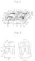
- FIG. 1 is an exploded perspective view showing an embodiment of the invention.
- FIG. 2 is a perspective view of the embodiment of the invention.
- FIG. 3 is an explanatory drawing of movement in the tracking direction.
- FIG. 4 is an explanatory drawing of movement in the direction of the optical axis.
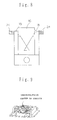
- FIG. 5 is a perspective view showing a statewhere an external force is applied in the tracking direction.
- FIG. 6 is an explanatory drawing of reaction forces and moments due to application of an external force.
- FIG. 7 is a model diagram of the system of the lens retaining member 20.
- FIG. 8 is a front view showing another embodiment of the invention.
- FIG. 9 is a perspective view showing a prior art example.
- FIG. 10 is a perspective view showing a prior art example.
- FIG. 11 is a perspective view showing a prior art example.
- FIG. 1 is an exploded perspective view of the embodiment of the invention.
- reference numeral 1 denotes a bed plate formed of a nonmagnetic metallic plate.
- the bed plate 1 around its one end, there is made a square through hole 2.
- magnet supporting pieces 3 and 4 being cut and raised up.
- magnet supporting piece 5 cut and raised up.
- Reference numeral 10 denotes a moving portion for supporting an objective lens 11.
- a connection base 13 in a spectacle form having two holes 12, 12 to be fitted on the moving portion holding pins 9, 9.
- a supporting base 14 having its tip end linearly joined to the connection base 13 at the center of it.
- the linear joint portion forms a hinge portion 15.
- the supporting base 14 has, at its portion next to the edge, a movable yoke 17 round which a tracking coil 16 is wound. Arms 18, 18 are extended from both sides of the movable yoke 17.
- connection base 13, the movable yoke 17 including the edge of the supporting base 14, and the arms 18, 18 are integrally formed by synthetic resin molding.
- the material used is for example polycarbonate resin having excellent flexibility.
- Four spring plates 19, 19, 19, 19 are horizontally extended from the obverse and the reverse of the arms 18, 18, respectively.
- the spring plate 19 is formed of a thin plate of a metallic spring material such as phosphor bronze and beryllium copper or a synthetic resin containing carbon fiber and having good resiliency, and it has holes made therein to weaken the spring force.
- the front end of the spring plate 19 are fixed to arms 21, 21, respectively, of a lens retaining member 20.
- the objective lens 11 is inserted in the center of the lens retaining member 20.
- the lens retaining member 20 is provided with tracking coils 22, 22 wound round it in the same direction as the tracking coil 16 and a focus coil 23 wound in the direction orthogonal to the tracking coil 22.
- FIG. 2 is a perspective view showing the objective lens supporting device structured by assembling the bed plate 1 and the moving portion 10.
- the entire body of the moving portion 10 of the objective lens supporting device is rotatable round the axial line of the hinge portion 15 and in a plane parallel to the plane of the bed plate 1. Since the lens retaining member 20 is in a plane parallel to the bed plate 1 and held by the four parallel spring plates 19, the lens retaining member 20 can move in the direction parallel to the axial line of the hinge portion 15. Further, the optical axis of the objective lens 11 is in parallel with the axial line of the hinge portion 15.
- a magnetic circuit for the focus direction is formed by the permanent magnet 6 and the permanent magnet 7. Further, a magnetic circuit for the tracking direction is formed by the permanent magnet 6 and the permanent magnet 8.
- the center of gravity of the entire body of the moving portion 10 is in agreement with the axial line of the hinge portion 15.
- the lens retaining member 20 is held by the supporting base 14 and the four parallel plate springs and allowed to move only in the focusing direction. Further, the center of the entire body of the lens retaining member 20 is in agreement with its center of gravity and the objective lens is fixed in the same position.
- a movement of the objective lens 11 in the tracking direction is achieved by flowing a current through the tracking coils 16, 16 wound round the movable yoke 17 and the tracking coils 22, 22 wound round the lens retaining member 20, with respect to the magnetic circuit formed of the permanent magnet 6 and the permanent magnet 8.
- the entire body of the moving portion 10 can be moved rotatively round the axial line of the hinge portion 15 as shown in FIG. 3.
- a movement of the objective lens 11 in the focusing direction is achieved by flowing a current through the focusing coil wound round the lens retaining member 20, with respect to the magnetic circuit formed of the permanent magnets 6 and 7, and, thereby, the lens retaining member 20 can be moved parallel to the optical axis of the objective lens 11 as shown in FIG. 4.
- M' > M a certain amount of a portion of the balancer 24 is cut off with a cutting tool such as nippers.
- M' ⁇ M a certain amount of a weight adjusting material such as adhesive agent is poured into a portion of the fins of the balancer 24 and solidified. At this time, such an adhesive agent that, when it is solidified, its portion of the solvent causes a loss in weight cannot be used.
- the present invention since it rotatively moves in the tracking direction with a balanced state maintained, vibration of the objective lens can be suppressed even if it is subjected to an external force due to an acceleration produced by the movement of the optical pickup. Further, by the decrease in weight of the moving portion, its tracking sensitivity in the focusing direction can be improved.
- the objective lens supporting device is balanced in the tracking direction, the objective lens can be controlled not to vibrate when the device is subjected to an external force due to an acceleration produced by the movement of the pickup. Therefore, an information signal can be written and/or read on an optical disk by the optical pickup device in a short time.
- the device can cope with a high speed rotation of an optical disk and, therefore, good signal writing and/or reading can be achieved.
- the device can achieve tracking adjustment for an optical disk having a greater facial warp or eccentricity and, therefore, good signal writing and/or reading can be achieved.
- the objective lens can be controlled not to vibrate when the device is subjected to an external force produced by movement, and since the need for an electric current for vibration control can be eliminated, power consumption of the drive mechanism can be reduced. Also other effects can be obtained.
Landscapes
- Optical Recording Or Reproduction (AREA)
- Optical Head (AREA)
- Lens Barrels (AREA)
Applications Claiming Priority (2)
| Application Number | Priority Date | Filing Date | Title |
|---|---|---|---|
| JP7205993A JPH0954969A (ja) | 1995-08-11 | 1995-08-11 | 対物レンズ支持装置 |
| JP205993/95 | 1995-08-11 |
Publications (1)
| Publication Number | Publication Date |
|---|---|
| EP0762395A1 true EP0762395A1 (de) | 1997-03-12 |
Family
ID=16516138
Family Applications (1)
| Application Number | Title | Priority Date | Filing Date |
|---|---|---|---|
| EP96305882A Withdrawn EP0762395A1 (de) | 1995-08-11 | 1996-08-12 | Haltevorrichtung für Objektivlinse |
Country Status (3)
| Country | Link |
|---|---|
| US (1) | US5781352A (de) |
| EP (1) | EP0762395A1 (de) |
| JP (1) | JPH0954969A (de) |
Cited By (1)
| Publication number | Priority date | Publication date | Assignee | Title |
|---|---|---|---|---|
| EP1475791A3 (de) * | 2003-05-01 | 2006-03-01 | System Engineers' Co. Ltd. | Antriebsgerät für die Linse eines optischen Abtastgerätes |
Families Citing this family (5)
| Publication number | Priority date | Publication date | Assignee | Title |
|---|---|---|---|---|
| JP3581533B2 (ja) * | 1997-08-08 | 2004-10-27 | パイオニア株式会社 | 光学式ピックアップ装置における対物レンズの姿勢調整機構 |
| US6473248B1 (en) | 1999-09-21 | 2002-10-29 | Matsushita Electronics Industrial Co. Ltd. | Method for manufacturing an optical pickup |
| JP3633491B2 (ja) * | 2001-02-05 | 2005-03-30 | ティアック株式会社 | 光ピックアップ装置 |
| KR100601688B1 (ko) * | 2004-06-22 | 2006-07-14 | 삼성전자주식회사 | 광픽업 액츄에이터 및 그 제조 방법 및 이를 적용한광픽업 및 광 기록 및/또는 재생기기 |
| JP4823837B2 (ja) * | 2006-09-29 | 2011-11-24 | 富士フイルム株式会社 | 撮像装置 |
Citations (11)
| Publication number | Priority date | Publication date | Assignee | Title |
|---|---|---|---|---|
| EP0212941A2 (de) * | 1985-08-16 | 1987-03-04 | Sony Corporation | Optische Lesekopfvorrichtungen |
| EP0343979A2 (de) * | 1988-05-25 | 1989-11-29 | Sharp Kabushiki Kaisha | Objektivlinsenantriebsgerät |
| US4887888A (en) * | 1984-01-30 | 1989-12-19 | Canon Kabushiki Kaisha | Objective lens driving device |
| EP0371799A1 (de) * | 1988-12-01 | 1990-06-06 | Kabushiki Kaisha Toshiba | Gerät zum Bewegen einer Objectivlinse mit einer viskoelastischen Substanz |
| EP0382553A1 (de) * | 1989-02-10 | 1990-08-16 | Kabushiki Kaisha Toshiba | Gerät zum Verstellen einer Objektivlinse |
| US4969715A (en) * | 1988-03-17 | 1990-11-13 | Sharp Kabushiki Kaisha | Device for supporting object lens in optical head |
| EP0410715A2 (de) * | 1989-07-25 | 1991-01-30 | Kabushiki Kaisha Toshiba | Blattfedervorrichtung und Herstellungsverfahren |
| US5231541A (en) * | 1991-05-16 | 1993-07-27 | Samsung Electronics Co., Ltd. | Driver for optical system |
| US5243584A (en) * | 1991-03-23 | 1993-09-07 | Hyundai Electronics Industries Co., Ltd. | Stabilized optical pick-up unit for use in a disk player |
| EP0617418A1 (de) * | 1993-03-22 | 1994-09-28 | Sony Corporation | Zweiachsige Positioniereinrichtung |
| US5414680A (en) * | 1991-08-16 | 1995-05-09 | Olympus Optical Co., Ltd. | Apparatus with a compact configuration for supporting an optical pick up device |
Family Cites Families (6)
| Publication number | Priority date | Publication date | Assignee | Title |
|---|---|---|---|---|
| JPH01113827U (de) * | 1988-01-21 | 1989-07-31 | ||
| US5050964A (en) * | 1988-06-25 | 1991-09-24 | Nec Home Electronics Ltd. | Objective lens supporting mechanism for use in an optical head of an optical disc apparatus |
| JP2536247Y2 (ja) * | 1989-09-26 | 1997-05-21 | 旭光学工業株式会社 | 光学式ヘッド装置 |
| JPH03165330A (ja) * | 1989-11-22 | 1991-07-17 | Konica Corp | 光ピックアップ |
| US5313334A (en) * | 1991-07-29 | 1994-05-17 | Sony Corporation | Objective lens moving actuator |
| JPH05205283A (ja) * | 1992-01-27 | 1993-08-13 | Sharp Corp | 光ピックアップの対物レンズ駆動装置 |
-
1995
- 1995-08-11 JP JP7205993A patent/JPH0954969A/ja active Pending
-
1996
- 1996-08-12 EP EP96305882A patent/EP0762395A1/de not_active Withdrawn
- 1996-08-12 US US08/695,937 patent/US5781352A/en not_active Expired - Fee Related
Patent Citations (11)
| Publication number | Priority date | Publication date | Assignee | Title |
|---|---|---|---|---|
| US4887888A (en) * | 1984-01-30 | 1989-12-19 | Canon Kabushiki Kaisha | Objective lens driving device |
| EP0212941A2 (de) * | 1985-08-16 | 1987-03-04 | Sony Corporation | Optische Lesekopfvorrichtungen |
| US4969715A (en) * | 1988-03-17 | 1990-11-13 | Sharp Kabushiki Kaisha | Device for supporting object lens in optical head |
| EP0343979A2 (de) * | 1988-05-25 | 1989-11-29 | Sharp Kabushiki Kaisha | Objektivlinsenantriebsgerät |
| EP0371799A1 (de) * | 1988-12-01 | 1990-06-06 | Kabushiki Kaisha Toshiba | Gerät zum Bewegen einer Objectivlinse mit einer viskoelastischen Substanz |
| EP0382553A1 (de) * | 1989-02-10 | 1990-08-16 | Kabushiki Kaisha Toshiba | Gerät zum Verstellen einer Objektivlinse |
| EP0410715A2 (de) * | 1989-07-25 | 1991-01-30 | Kabushiki Kaisha Toshiba | Blattfedervorrichtung und Herstellungsverfahren |
| US5243584A (en) * | 1991-03-23 | 1993-09-07 | Hyundai Electronics Industries Co., Ltd. | Stabilized optical pick-up unit for use in a disk player |
| US5231541A (en) * | 1991-05-16 | 1993-07-27 | Samsung Electronics Co., Ltd. | Driver for optical system |
| US5414680A (en) * | 1991-08-16 | 1995-05-09 | Olympus Optical Co., Ltd. | Apparatus with a compact configuration for supporting an optical pick up device |
| EP0617418A1 (de) * | 1993-03-22 | 1994-09-28 | Sony Corporation | Zweiachsige Positioniereinrichtung |
Cited By (1)
| Publication number | Priority date | Publication date | Assignee | Title |
|---|---|---|---|---|
| EP1475791A3 (de) * | 2003-05-01 | 2006-03-01 | System Engineers' Co. Ltd. | Antriebsgerät für die Linse eines optischen Abtastgerätes |
Also Published As
| Publication number | Publication date |
|---|---|
| JPH0954969A (ja) | 1997-02-25 |
| US5781352A (en) | 1998-07-14 |
Similar Documents
| Publication | Publication Date | Title |
|---|---|---|
| US4887888A (en) | Objective lens driving device | |
| US4811320A (en) | Optical type pickup apparatus with lens holder supported by frame wires each having an end inserted into a frame hole | |
| EP0137283A1 (de) | Optischer Kopf | |
| US5220459A (en) | Optical disk driving with inertial damping spring supporting lens holder | |
| US4782475A (en) | Flexure supported read head | |
| US5781352A (en) | Objective lens supporting device | |
| KR950010329B1 (ko) | 정보기록재생장치의 광학부 구동장치 | |
| JPH0294126A (ja) | 対物レンズ駆動装置 | |
| JP4108434B2 (ja) | 対物レンズ駆動装置および光ピックアップ装置ならびに光ディスク装置 | |
| US20020057631A1 (en) | Fringing field focus motor and mechanism for optical disk drive | |
| JP2827563B2 (ja) | 対物レンズ駆動装置 | |
| JPH01317234A (ja) | 対物レンズ駆動装置 | |
| JPH0471257B2 (de) | ||
| US6996039B2 (en) | Optical pick-up actuator | |
| JP3375228B2 (ja) | レンズ駆動装置 | |
| KR100206339B1 (ko) | 광 디스크 플레이어의 엑추에이터 장치 | |
| JP2735127B2 (ja) | 光学系駆動装置 | |
| JPS6258430A (ja) | 光学ヘツド装置 | |
| JPS6076039A (ja) | 対物レンズ駆動装置 | |
| JP2633427B2 (ja) | 光ディスク装置 | |
| JPH04243029A (ja) | トラツキング用回動ミラー装置 | |
| JPH0242631A (ja) | 対物レンズ駆動装置 | |
| JPH04330642A (ja) | 光学素子駆動装置 | |
| JPS60167137A (ja) | 三次元駆動装置 | |
| JPH0772945B2 (ja) | 対物レンズ駆動装置 |
Legal Events
| Date | Code | Title | Description |
|---|---|---|---|
| PUAI | Public reference made under article 153(3) epc to a published international application that has entered the european phase |
Free format text: ORIGINAL CODE: 0009012 |
|
| AK | Designated contracting states |
Kind code of ref document: A1 Designated state(s): DE FR GB NL |
|
| STAA | Information on the status of an ep patent application or granted ep patent |
Free format text: STATUS: THE APPLICATION IS DEEMED TO BE WITHDRAWN |
|
| 18D | Application deemed to be withdrawn |
Effective date: 19970913 |