EP0212941A2 - Optische Lesekopfvorrichtungen - Google Patents
Optische Lesekopfvorrichtungen Download PDFInfo
- Publication number
- EP0212941A2 EP0212941A2 EP86306257A EP86306257A EP0212941A2 EP 0212941 A2 EP0212941 A2 EP 0212941A2 EP 86306257 A EP86306257 A EP 86306257A EP 86306257 A EP86306257 A EP 86306257A EP 0212941 A2 EP0212941 A2 EP 0212941A2
- Authority
- EP
- European Patent Office
- Prior art keywords
- support member
- optical
- rotation axis
- rotation
- axis
- Prior art date
- Legal status (The legal status is an assumption and is not a legal conclusion. Google has not performed a legal analysis and makes no representation as to the accuracy of the status listed.)
- Granted
Links
Images


Classifications
-
- G—PHYSICS
- G11—INFORMATION STORAGE
- G11B—INFORMATION STORAGE BASED ON RELATIVE MOVEMENT BETWEEN RECORD CARRIER AND TRANSDUCER
- G11B7/00—Recording or reproducing by optical means, e.g. recording using a thermal beam of optical radiation by modifying optical properties or the physical structure, reproducing using an optical beam at lower power by sensing optical properties; Record carriers therefor
- G11B7/08—Disposition or mounting of heads or light sources relatively to record carriers
- G11B7/09—Disposition or mounting of heads or light sources relatively to record carriers with provision for moving the light beam or focus plane for the purpose of maintaining alignment of the light beam relative to the record carrier during transducing operation, e.g. to compensate for surface irregularities of the latter or for track following
- G11B7/0925—Electromechanical actuators for lens positioning
- G11B7/0932—Details of sprung supports
-
- G—PHYSICS
- G11—INFORMATION STORAGE
- G11B—INFORMATION STORAGE BASED ON RELATIVE MOVEMENT BETWEEN RECORD CARRIER AND TRANSDUCER
- G11B7/00—Recording or reproducing by optical means, e.g. recording using a thermal beam of optical radiation by modifying optical properties or the physical structure, reproducing using an optical beam at lower power by sensing optical properties; Record carriers therefor
- G11B7/08—Disposition or mounting of heads or light sources relatively to record carriers
- G11B7/09—Disposition or mounting of heads or light sources relatively to record carriers with provision for moving the light beam or focus plane for the purpose of maintaining alignment of the light beam relative to the record carrier during transducing operation, e.g. to compensate for surface irregularities of the latter or for track following
- G11B7/0925—Electromechanical actuators for lens positioning
- G11B7/093—Electromechanical actuators for lens positioning for focusing and tracking
Definitions
- This invention relates to optical pick-up devices suitable for use in recording on and reproducing from an optical recording medium.
- the data Upon recording of data from a music or image source on an optical disc recording medium, the data are converted into a digital signal having logic "0" and "1" levels. According to the logic level, pits are formed to provide a continuous spiral recording track in the optical disc recording medium.
- An optical pick-up device is used to reproduce the recorded data by radiating a light beam from a light source such as a semiconductor laser through an objective lens which focuses the light beam on the optical disc recording medium, and sensing the light beam reflected from the optical recording medium to determine the presence of pits.
- the objective lens is supported in such a manner that its optical axis can follow the spiral recording track while the optical disc is rotating during the data reproducing operation.
- the objective lens is supported at a predetermined constant distance from the optical disc recording medium to focus the light beam so as to produce a light spot of a predetermined constant diameter.
- the error in the distance of the objective lens from the optical disc recording medium should be less than the pit depth, that is, about 0.1 nm.
- optical pick-up devices have normally been designed to move the objective lens in a tracking direction perpendicular to the optical axis and also in a focusing direction parallel to the optical axis for the purpose of adjustment of the optical axis to a desired position.
- an optical pick-up device tends to deviate from a desired position in the tracking direction when it is subject to an impact or sudden movement particularly in the tracking direction.
- an optical pick-up device comprising a base, an objective lens having an optical axis for focusing a light beam emitted from a light source onto an optical recording medium, a support member carrying said objective lens thereon, a coupling unit coupling said support member to said base for permitting movement of said support member, and means responsive to a light beam reflected from said optical recording medium for exerting a force on said support member to move said objective lens;
- a preferred embodiment of the optical pick-up device comprises a base, an objective lens having an optical axis for focusing a light beam emitted from a light source on an optical recording medium, and a support member carrying the objective lens thereon.
- a coupling unit is coupled between the support member and the base.
- the coupling unit has a first rotation axis parallel to the optical axis for permitting rotation of the support member about the first rotation axis in a tracking direction perpendicular to the optical axis.
- the coupling unit also has a second rotation axis perpendicular to the optical axis for permitting rotation of the support member about the second rotation axis in a focusing direction parallel to the optical axis.
- the support member has a centre of gravity positioned substantially on the first rotation axis.
- a light beam reflected from the optical recording medium is sensed for deriving a force applied to the support member to move the objective lens in the focusing and/or tracking direction to adjust the optical axis to a desired position.
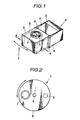
- FIG. 1 shows a optical pick-up device disclosed, for example, in our US patent US-A-4 449 213.
- the optical pick-up device a includes a support member b which is coupled to a sliding member d through a pair of parallel resilient arms e such as leaf springs.
- An objective lens c is mounted on the support member b with its optical axis directed in a focusing direction.
- the sliding member d can slide on a suitable member (not shown) in a direction parallel to the optical axis, permitting the support member b to move in the focusing direction, whereas the parallel resilient arms e can move in a direction perpendicular to the optical axis, permitting the support member b to move in the tracking direction.
- a moment moves the support member b a distance X in the tracking direction.
- FIG 2 shows another type of optical pick-up device as disclosed, for example, in our US patent US-A-4 482 988.
- the optical pick-up device f includes a support cylinder g placed around a support shaft i extending through a through-hole h formed centrally in the support cylinder g.
- An objective lens j is mounted on the support cylinder g with its optical axis directed in a focussing direction.
- a balancer weight k is provided on the support cylinder at a position opposite to the objective lens j with respect to the support shaft i to minimize the moment which would tend to rotate the support cylinder g when it is subject to an impact.
- the support shaft i is placed with a clearance in the through-hole h for permitting the support cylinder g to rotate about and move along the support shaft i. When an impact occurs, the support cylinder g will move in the tracking direction within the clearance.
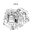
- the optical pick-up device 1 includes an objective lens 23 for use in focusing a light beam emitted by a light source (not shown) onto an optical disc recording medium (not shown).
- the objective lens 23 is attached to a support member 19 with its optical axis directed to the optical disc recording medium.
- the support member 19 is mounted on a base substrate 2 through a coupling unit 10 which has a first rotation axis parallel to the optical axis for permitting rotation of the support member 19 about the first rotation axis in a tracking direction perpendicular to the optical axis, and also a second rotation axis perpendicular to the optical axis for permitting rotation of the support member 19 about the second rotation axis in a focusing direction parallel to the optical axis.
- the objective lens 23 is fixed within an annular lens holder 24.
- the support member 19 has an aperture 20 having its inner surface conforming generally to the circumferential surface of the lens holder 24.
- An annular ring 20a is formed integrally on the inner surface of the aperture 20 substantially intermediate between the opposite ends of the aperture 20.
- the lens holder 24 is press fitted in the aperture 20 with its bottom in abutment with the annular ring 20a.
- a first balancer weight 25 is fixedly fitted in the lower half portion of the aperture 20 with its top in abutment with the annular ring 20a.
- the support member 19 has a pair of rearwardly extending parallel wings 19b each having a hole 22 formed therein near its rear end.
- the parallel wings 19b carry a second balancer weight 26 which is of a cylindrical shape having small diameter portions 26a on the opposite ends thereof.
- the second balancer weight 26 is mounted between the parallel wings 19b with their small diameter portions 26a fitted respectively in the holes 22.
- the parallel wings 19b also have inwardly extending projections formed near their forward ends to provide grooves 21 facing each other.
- a pair of drive coil assemblies 27 are attached on the opposite side surfaces of the support membetl9, each including a rectangular coil frame 28 around which a focusing coil 30 is wound to produce magnetic lines of force directed in the focusing direction when it is energized.
- the focusing coils 30 are attached on the opposite side surfaces of the support member 19.
- a pair of square coil plates 29 are attached side by side on the outer side surface of each of the focusing coils 30 with each carrying a tracking coil 31 which produces magnetic lines of force directed in the tracking direction when it is energized.
- the coupling unit 10 includes a mounting base 11 secured on the base substrate 2, a parallel link 13, and a hinge member 15, these parts being made integrally of a synthetic resin.
- the mounting base 11 is provided near its opposite ends with bolt holes 12 whereby it may be bolted to the base substrate 2.
- the hinge member 15 is of a cubic shape having cut-outs formed in the opposite side surfaces thereof to provide a flexible thin hinge connection 15c between front and rear hinge members 15a and 15b, the hinge connection 15c having a hinge or first rotation axis parallel to the optical axis about which the front hinge member 15a can rotate with respect to the rear hinge member 15b.
- the parallel link 13 comprises upper and lower hinge members 13a and 13b extending in parallel-spaced relation between the mounting base 11 and the hinge member 15.
- the upper hinge member 13a is of a trapezoidal shape having at its one end a flexible thinned portion connected with the upper edge of the mounting base 11 and at the other end thereof a flexible thinned portion connected with the upper edge of the rear hinge member 15b.
- the lower hinge member 13b is of an inverted-trapezoidal shape having at its one end a flexible thinned portion connected with the lower edge of the mounting base 11 and at the other end thereof a flexible thinned portion connected with the lower edge of the rear hinge member 15b.
- the coupling unit 10 is coupled to the support member 19 with its front hinge member 15a being fitted and stuck in the grooves 21 and with the second balancer weight 26 being placed between the upper and lower hinge members 13a and 13b.
- the parallel link 13 has a second rotation axis perpendicular to the optical axis about which the hinge member 15 can rotate in the focusing direction with respect to the mounting base 11. It is, therefore, apparent from the foregoing that the coupling unit 10 has a first rotation axis parallel to the optical axis for permitting rotation of the support member 19 about the first rotation axis in the tracking direction perpendicular to the optical axis, and a second rotation axis perpendicular to the optical axis for permitting rotation of the support member 19 about the second rotation axis in the focusing direction parallel to the optical axis. In other words, the coupling unit 10 permits the objective lens 23 to rotate in the focusing and/or tracking direction with respect to the base substrate 2.
- the base substrate 2 has a mounting platform 5 formed on the rear end portion thereof at a position substantially intermediate between the opposite side edges.
- the mounting platform 5 is provided near its opposite ends with threaded holes 6 in which bolts 17 are threaded to secure the mounting base 11 on the base substrate 2. Washers 18 are interposed between the mounting base 11 and the bolt heads.
- the base substrate 2 is also provided with a centre opening 4 formed in a shape which corresponds to and is slightly greater than that of the support member 19.
- a pair of inner yokes 7 is provided on the base substrate 2 adjacent to the side edges of the centre opening 4.
- the rectangular coil frames 28 are placed loosely around the respective inner yokes 7 to permit the support member 19 to move in the focusing and tracking directions.
- the base substrate 2 is also provided thereon with a. pair of outer yokes 8 facing in parallel-spaced relation to the respective inner yokes 7.
- Magnets 9 and 9' formed in the same shape as the inner and outer yokes 7 and 8, are attached on the inner surface of each of the outer yokes 8 in such a manner that the inner and outer yokes 7 and 8 and the magnets 9 and 9' establish a magnetic circuit producing magnetic lines of force perpendicular to the optical axis in which the drive coil assemblies 27 are placed.
- the base substrate 2 is provided at its corners with bolt holes 3 whereby it may be bolted on an optical block (not shown) which carries a semiconductor laser for producing a laser beam, a quarter-wave plate and a collimation lens through which the laser beam is guided to the objective lens 23, a polarizing beam splitter which separates the incident beam into the laser beam emitted from the semiconductor laser and the beam reflected on the optical disc, a photo sensor for sensing the reflected beam, and a control circuit responsive to the photo sensor for producing focusing and tracking error signals which are used to produce correction currents for the focusing and tracking coils 30 and 31.
- the laser beam emitted from the semiconductor laser passes upward through the centre opening 4 in the base substrate 2, as indicated by the two-dotted arrows in Figure 4.
- first and second balancer weights 25 and 26 are provided for the purpose of making up the balance of the weight of the support member 19 in such a manner as to position the centre of gravity of the support member 19 on the first rotation or hinge axis of the hinge member 15. This is effective to minimize the possibility of movement of the support member 19 causing the objective lens 23 to deviate in the tracking direction from a correct position when the optical pick-up device 1 is subject to an impact or a sudden movement particularly in the tracking direction.
- the operation is as follows.
- the laser beam from the semiconductor laser device passes through the objective lens 23 and is reflected on the optical disc.
- a part of the reflected beam from the optical disc returns through the objective lens 23 to the optical block which contains a control unit.
- the control unit receives a signal from the photo sensor and reads deviations of the position of the objective lens 23 in the focusing and tracking directions.
- the control unit provides correction currents, which correspond to the sensed deviations, for the focusing and tracking coils 30 and 31.
- the current flows through the respective focusing coils 30 disposed in the magnetic flux produced in the magnetic circuit cause forces on the respective focusing coils 30 to move the support member 19 in the focusing direction so as to correct the distance between the objective lens 23 and the optical disc recording surface.
- the direction of movement of the support member 19 is dependent both on the direction of the current flow through the focusing coils 30 and on the direction of the magnetic flux produced in the magnetic circuit.
- the current flows through the respective tracking coils 31 disposed in the magnetic flux produced in the magnetic circuit cause forces on the respective tracking coils 31 to rotate the support member 19 in the tracking direction about the first rotation or hinge axis of the hinge member 15 so as to direct the objective lens optical axis to the centre of the optical disc recording track.
- the direction of rotation of the tracking coils 31 is dependent on the directions of the current flows through the tracking coils 31 and also on the direction of the magnetic flux produced in the magnetic circuit.
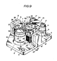
- FIG. 7 to 10 there is shown a second embodiment of the invention which differs from the first embodiment only in the support arm arrangement. Accordingly, like parts are designated by like reference numerals.
- a coupling unit 32 includes a parallel link comprising two resilient plates such, for example, as leaf springs 33, which are placed in parallel-spaced relation to couple the hinge member 15 with the mounting base 11.
- the upper leaf spring 33 has a front end portion stuck on the upper surface of the rear hinge member 15b and a rear end portion stuck on the upper surface of the mounting base 11.
- the lower leaf spring 33 has a rear end portion stuck on the lower surface of the rear hinge member 15b and a rear end portion attached on the lower surface of the mounting base 11.
- a washer 34 is secured by the bolts 17 on the upper surface of the mounting base 11 to press the upper leaf spring rear end portion against the upper surface of the mounting base 11.
- the lower leaf spring rear end portion is sandwiched between the mounting base 11 and the mounting platform 5.
- the parallel link coupling unit 32 comprising the upper and lower leaf springs 33, has a resilient property permitting rotation of the support member 19 about a second rotation axis in the focusing direction with respect to the mounting base 11. - It is, therefore, apparent that, also in this embodiment, the coupling unit 32 has a first rotation axis parallel to the optical axis for permitting rotation of the support member 19 about a second rotation axis in the focusing direction parallel to the optical axis.
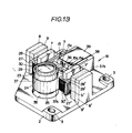
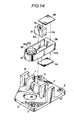
- FIG. 11 and 14 there is shown a third embodiment of the invention comprising a support member 37 which carries the objective lens 23 thereon.
- the support member 37 differs from that of the first embodiment in that the parallel wings are connected integrally by a rear frame 38.
- the rear frame 38 also serves as a second balancer weight as described in connection with the first embodiment.
- the coupling unit includes a parallel link comprising two resilient plates such, for example, as leaf springs 39 placed in parallel-spaced relation to connect the hinge member 15 with the support member rear frame 38.
- the upper leaf spring 39 has a front end portion stuck on the upper surface of the rear hinge member 15b and a rear end portion stuck on the lower surface of the rear frame 38.
- the front hinge member 15a is stuck on the rear surface of a mounting member 36 provided on the base substrate 2.
- the base substrate 2 is formed with a circular opening 35 which corresponds to the circular aperture 20 provided in the support member 37.
- the parallel link comprising the upper and lower leaf springs 39, has a resilient property permitting rotation of the support member 19 about a second rotation axis in the focusing direction with respect to the mounting member 36.
- the coupling unit has a first rotation axis parallel to the optical axis for permitting rotation of the support member 37 about the first rotation axis in the tracking direction perpendicular to the optical axis and a second rotation axis perpendicular to the optical axis for permitting rotation of the support member 37 about the second rotation axis in the focusing direction parallel to the optical axis.
- a balancer weight 25 is secured in the circular opening 20 in the same manner as described in connection with the first embodiment to position the centre of gravity of the support member 37 on the first rotation or hinge axis of the hinge member 15.
- the support member carrying an objective lens thereon is coupled to a base substrate through a coupling unit which has a first rotation axis for permitting rotation of the support member about the first rotation axis in a tracking direction and a second rotation axis for permitting rotation of the support member about the second rotation axis in a focusing direction.
- the support member is designed to have a centre of gravity positioned substantially on the first rotation axis so as to minimize the possibility of a deviation of the optical axis of the objective lens in the tracking direction from a desired position when the optical pick-up device is subject to an impact or sudden movement particularly in the tracking direction.
Landscapes
- Optical Recording Or Reproduction (AREA)
- Mechanical Optical Scanning Systems (AREA)
- Die Bonding (AREA)
- Supporting Of Heads In Record-Carrier Devices (AREA)
- Lasers (AREA)
- Moving Of The Head For Recording And Reproducing By Optical Means (AREA)
- Optical Head (AREA)
- Facsimile Heads (AREA)
Priority Applications (1)
| Application Number | Priority Date | Filing Date | Title |
|---|---|---|---|
| AT86306257T ATE74681T1 (de) | 1985-08-16 | 1986-08-13 | Optische lesekopfvorrichtungen. |
Applications Claiming Priority (2)
| Application Number | Priority Date | Filing Date | Title |
|---|---|---|---|
| JP60180145A JPH0668843B2 (ja) | 1985-08-16 | 1985-08-16 | 光学ピツクアツプ装置 |
| JP180145/85 | 1985-08-16 |
Publications (3)
| Publication Number | Publication Date |
|---|---|
| EP0212941A2 true EP0212941A2 (de) | 1987-03-04 |
| EP0212941A3 EP0212941A3 (en) | 1989-01-18 |
| EP0212941B1 EP0212941B1 (de) | 1992-04-08 |
Family
ID=16078188
Family Applications (1)
| Application Number | Title | Priority Date | Filing Date |
|---|---|---|---|
| EP86306257A Expired - Lifetime EP0212941B1 (de) | 1985-08-16 | 1986-08-13 | Optische Lesekopfvorrichtungen |
Country Status (8)
| Country | Link |
|---|---|
| US (1) | US4766583A (de) |
| EP (1) | EP0212941B1 (de) |
| JP (1) | JPH0668843B2 (de) |
| KR (1) | KR950014833B1 (de) |
| AT (1) | ATE74681T1 (de) |
| CA (1) | CA1268369A (de) |
| DE (1) | DE3684734D1 (de) |
| HK (1) | HK160295A (de) |
Cited By (13)
| Publication number | Priority date | Publication date | Assignee | Title |
|---|---|---|---|---|
| EP0287235A3 (en) * | 1987-04-15 | 1989-03-15 | Pioneer Electronic Corporation | Pickup actuator for disk-type media |
| DE3831425A1 (de) * | 1987-09-16 | 1989-04-06 | Sankyo Seiki Seisakusho Kk | Optische abnehmervorrichtung |
| EP0316846A3 (en) * | 1987-11-13 | 1990-08-22 | Kabushiki Kaisha Toshiba | Optical apparatus |
| EP0333512A3 (en) * | 1988-03-17 | 1990-11-28 | Sharp Kabushiki Kaisha | Device for supporting object lens in optical head |
| EP0358294A3 (en) * | 1988-09-01 | 1990-11-28 | Pioneer Electronic Corporation | Optical pickup device |
| EP0343979A3 (de) * | 1988-05-25 | 1991-01-09 | Sharp Kabushiki Kaisha | Objektivlinsenantriebsgerät |
| EP0326246A3 (de) * | 1988-01-27 | 1991-04-03 | Sony Corporation | Objektivlinsenantriebsgerät |
| EP0427441A3 (en) * | 1989-11-10 | 1991-11-06 | Canon Kabushiki Kaisha | Objective lens actuator |
| EP0455365A3 (en) * | 1990-04-16 | 1992-01-29 | International Business Machines Corporation | Movable lens support structure having required resonant frequency characteristics |
| US5182738A (en) * | 1989-11-10 | 1993-01-26 | Canon Kabushiki Kaisha | Objective lens actuator using a balance weight therein |
| US5199014A (en) * | 1990-06-29 | 1993-03-30 | U.S. Philips Corporation | Two axis electro-optical scanning device having orthogonal coils sharing one air gap |
| EP0762395A1 (de) * | 1995-08-11 | 1997-03-12 | Minebea Co.,Ltd. | Haltevorrichtung für Objektivlinse |
| US5726968A (en) * | 1991-11-07 | 1998-03-10 | U.S. Philips Corporation | Electro-optical scanning device, hinge element for use in the scanning device, and optical player comprising the scanning device |
Families Citing this family (44)
| Publication number | Priority date | Publication date | Assignee | Title |
|---|---|---|---|---|
| JP2541963B2 (ja) * | 1987-02-27 | 1996-10-09 | オリンパス光学工業株式会社 | 対物レンズ駆動装置 |
| US4922477A (en) * | 1987-05-30 | 1990-05-01 | Nec Home Electronics Ltd. | Optical head unit |
| JPS6459647A (en) * | 1987-08-31 | 1989-03-07 | Nippon Denki Home Electronics | Objective lens actuator for optical head |
| JPS6442520U (de) * | 1987-09-08 | 1989-03-14 | ||
| US5050964A (en) * | 1988-06-25 | 1991-09-24 | Nec Home Electronics Ltd. | Objective lens supporting mechanism for use in an optical head of an optical disc apparatus |
| US5132944A (en) * | 1988-09-20 | 1992-07-21 | Hewlett-Packard Company | Half-height magneto-optic disk drive |
| JPH0679384B2 (ja) * | 1988-09-30 | 1994-10-05 | 日本電気株式会社 | 対物レンズ駆動装置 |
| US5206762A (en) * | 1988-12-01 | 1993-04-27 | Kabushiki Kaisha Toshiba | Viscoelastic substance and objective lens driving apparatus with the same |
| JPH0758553B2 (ja) * | 1989-01-12 | 1995-06-21 | 日本電気株式会社 | 対物レンズ駆動装置 |
| EP0382553B1 (de) * | 1989-02-10 | 1996-01-03 | Kabushiki Kaisha Toshiba | Gerät zum Verstellen einer Objektivlinse |
| JP2684762B2 (ja) * | 1989-04-20 | 1997-12-03 | ソニー株式会社 | 対物レンズ駆動装置 |
| JPH0734495Y2 (ja) * | 1989-05-09 | 1995-08-02 | パイオニア株式会社 | 光学式ピックアップ |
| US5265079A (en) | 1991-02-15 | 1993-11-23 | Applied Magnetics Corporation | Seek actuator for optical recording |
| US6141300A (en) | 1989-06-20 | 2000-10-31 | Discovision Associates | Optical actuator including lens assembly with optical axis having symmetric suspensory forces acting thereon and optical disc system including same |
| US5150343A (en) * | 1989-07-19 | 1992-09-22 | Matsushita Electric Industrial Co., Ltd. | Miniaturized low-power-consumption optical head provided with a state transformation mechanism |
| US5253402A (en) * | 1989-07-25 | 1993-10-19 | Kabushiki Kaisha Toshiba | Method of manufacturing a leaf spring mechanism |
| JPH03104027A (ja) * | 1989-09-18 | 1991-05-01 | Sony Corp | 対物レンズ駆動装置 |
| US5293363A (en) * | 1989-10-13 | 1994-03-08 | Mitsubishi Denki Kabushiki Kaisha | Optical head apparatus with light weight movable lens holder |
| JP2765633B2 (ja) * | 1989-11-02 | 1998-06-18 | オリンパス光学工業株式会社 | 光学系支持装置 |
| JPH077522B2 (ja) * | 1990-01-31 | 1995-01-30 | シャープ株式会社 | レンズ駆動用支持体 |
| KR920015291A (ko) * | 1991-01-31 | 1992-08-26 | 강진구 | 광학기록 및 재생장치의 대물렌즈 구동수단 |
| US5729511A (en) | 1991-02-15 | 1998-03-17 | Discovision Associates | Optical disc system having servo motor and servo error detection assembly operated relative to monitored quad sum signal |
| US5677899A (en) | 1991-02-15 | 1997-10-14 | Discovision Associates | Method for moving carriage assembly from initial position to target position relative to storage medium |
| US6069857A (en) | 1991-02-15 | 2000-05-30 | Discovision Associates | Optical disc system having improved circuitry for performing blank sector check on readable disc |
| US6236625B1 (en) | 1991-02-15 | 2001-05-22 | Discovision Associates | Optical disc system having current monitoring circuit with controller for laser driver and method for operating same |
| JPH0534617A (ja) * | 1991-07-26 | 1993-02-12 | Minolta Camera Co Ltd | レーザビーム走査光学装置 |
| US5313334A (en) * | 1991-07-29 | 1994-05-17 | Sony Corporation | Objective lens moving actuator |
| KR950004797B1 (ko) * | 1991-12-31 | 1995-05-10 | 삼성전자주식회사 | 레이져 디스크 플레이어의 광픽업 장치 |
| JPH05258325A (ja) * | 1992-01-13 | 1993-10-08 | Sharp Corp | 対物レンズ駆動装置 |
| US5461598A (en) * | 1992-09-18 | 1995-10-24 | Eastman Kodak Company | Balanced focus actuator for an optical storage system |
| US5432763A (en) * | 1993-03-15 | 1995-07-11 | Hewlett-Packard Company | Subminiature rotary actuator optical head |
| US5519677A (en) * | 1993-03-22 | 1996-05-21 | Sony Corporation | Biaxial actuator for driving an objective lens in both focusing and tracking directions |
| US5428589A (en) * | 1993-08-17 | 1995-06-27 | Eastman Kodak Company | Apparatus and method for an electromagnetic actuator with two orthogonal axes of motion |
| JP3279024B2 (ja) * | 1993-10-30 | 2002-04-30 | ソニー株式会社 | 光ピックアップ装置 |
| JP3246140B2 (ja) * | 1993-11-16 | 2002-01-15 | ソニー株式会社 | 対物レンズ駆動装置 |
| JP3319481B2 (ja) * | 1993-12-22 | 2002-09-03 | ソニー株式会社 | 対物レンズ駆動装置及びこれを利用した光ディスク装置 |
| US5898652A (en) * | 1994-07-08 | 1999-04-27 | Seiko Epson Corporation | Support structure for an optical pickup |
| JPH0830991A (ja) * | 1994-07-08 | 1996-02-02 | Seiko Epson Corp | 光ピックアップ装置 |
| US6434087B1 (en) | 1995-01-25 | 2002-08-13 | Discovision Associates | Optical disc system and method for controlling bias coil and light source to process information on a storage medium |
| JP2572081Y2 (ja) * | 1995-04-05 | 1998-05-20 | シャープ株式会社 | 対物レンズ支持装置 |
| JP3881634B2 (ja) * | 2002-09-20 | 2007-02-14 | シャープ株式会社 | 光ピックアップ装置およびその調整方法 |
| GB0315273D0 (en) * | 2003-07-01 | 2003-08-06 | 1 Ltd | Lens suspension and actuation apparatus |
| EP1783760B1 (de) * | 2005-11-07 | 2009-05-06 | Thomson Licensing S.A. | Vorrichtung zum Lesen von und/oder Schreiben auf optischen Aufzeichnungsmedien |
| EP1783757A1 (de) * | 2005-11-07 | 2007-05-09 | Deutsche Thomson-Brandt Gmbh | Gerät zum Lesen und/oder Beschreiben optischer Aufzeichnungsträger |
Family Cites Families (13)
| Publication number | Priority date | Publication date | Assignee | Title |
|---|---|---|---|---|
| JPS57103131A (en) * | 1980-12-18 | 1982-06-26 | Sony Corp | Biaxial driver |
| JPS57120240A (en) * | 1981-01-16 | 1982-07-27 | Sony Corp | Optical disk player |
| JPS57178233A (en) * | 1981-04-27 | 1982-11-02 | Sony Corp | Supporting structure of optical system |
| US4475179A (en) * | 1982-06-30 | 1984-10-02 | Eastman Kodak Company | Optical disc write/read methods and apparatus with improved focus and tracking control |
| JPS5914134U (ja) * | 1982-07-19 | 1984-01-28 | パイオニア株式会社 | 可動体の支持構造 |
| JPS5920438U (ja) * | 1982-07-27 | 1984-02-07 | パイオニア株式会社 | 光学式情報読取装置における光学系駆動装置 |
| JPS59168839U (ja) * | 1983-04-28 | 1984-11-12 | パイオニア株式会社 | 光学式情報読取装置における光学部品の駆動機構 |
| DE3469814D1 (en) * | 1983-05-31 | 1988-04-14 | Matsushita Electric Industrial Co Ltd | Apparatus for driving objective lens of optical disc player |
| US4615355A (en) * | 1983-09-26 | 1986-10-07 | Garcia Gervasio B | Automobile anti-theft device |
| US4633456A (en) * | 1984-01-23 | 1986-12-30 | International Business Machines Corporation | Two axis electromagnetic actuator |
| JPH064415Y2 (ja) * | 1984-04-23 | 1994-02-02 | パイオニア株式会社 | レンズ駆動装置 |
| NL8403052A (nl) * | 1984-10-08 | 1986-05-01 | Philips Nv | Optische inrichting. |
| JPH0750526B2 (ja) * | 1986-03-15 | 1995-05-31 | ソニー株式会社 | デイスクプレ−ヤの光学ヘツド装置 |
-
1985
- 1985-08-16 JP JP60180145A patent/JPH0668843B2/ja not_active Expired - Lifetime
-
1986
- 1986-08-11 CA CA000515664A patent/CA1268369A/en not_active Expired - Lifetime
- 1986-08-13 AT AT86306257T patent/ATE74681T1/de not_active IP Right Cessation
- 1986-08-13 EP EP86306257A patent/EP0212941B1/de not_active Expired - Lifetime
- 1986-08-13 DE DE8686306257T patent/DE3684734D1/de not_active Expired - Lifetime
- 1986-08-14 KR KR1019860006711A patent/KR950014833B1/ko not_active Expired - Lifetime
- 1986-08-15 US US06/896,922 patent/US4766583A/en not_active Expired - Lifetime
-
1995
- 1995-10-12 HK HK160295A patent/HK160295A/en not_active IP Right Cessation
Cited By (17)
| Publication number | Priority date | Publication date | Assignee | Title |
|---|---|---|---|---|
| US5043964A (en) * | 1987-04-15 | 1991-08-27 | Pioneer Electronic Corporation | Linear pickup actuator for moving an optical pickup in a radial direction of a disk |
| EP0287235A3 (en) * | 1987-04-15 | 1989-03-15 | Pioneer Electronic Corporation | Pickup actuator for disk-type media |
| DE3831425C2 (de) * | 1987-09-16 | 1998-01-22 | Sankyo Seiki Seisakusho Kk | Optische Abnehmervorrichtung |
| DE3831425A1 (de) * | 1987-09-16 | 1989-04-06 | Sankyo Seiki Seisakusho Kk | Optische abnehmervorrichtung |
| EP0316846A3 (en) * | 1987-11-13 | 1990-08-22 | Kabushiki Kaisha Toshiba | Optical apparatus |
| EP0326246A3 (de) * | 1988-01-27 | 1991-04-03 | Sony Corporation | Objektivlinsenantriebsgerät |
| US5073883A (en) * | 1988-01-27 | 1991-12-17 | Sony Corporation | Objective lens driving apparatus including parallalogram structure |
| EP0333512A3 (en) * | 1988-03-17 | 1990-11-28 | Sharp Kabushiki Kaisha | Device for supporting object lens in optical head |
| EP0343979A3 (de) * | 1988-05-25 | 1991-01-09 | Sharp Kabushiki Kaisha | Objektivlinsenantriebsgerät |
| EP0358294A3 (en) * | 1988-09-01 | 1990-11-28 | Pioneer Electronic Corporation | Optical pickup device |
| EP0427441A3 (en) * | 1989-11-10 | 1991-11-06 | Canon Kabushiki Kaisha | Objective lens actuator |
| US5182738A (en) * | 1989-11-10 | 1993-01-26 | Canon Kabushiki Kaisha | Objective lens actuator using a balance weight therein |
| EP0455365A3 (en) * | 1990-04-16 | 1992-01-29 | International Business Machines Corporation | Movable lens support structure having required resonant frequency characteristics |
| US5199014A (en) * | 1990-06-29 | 1993-03-30 | U.S. Philips Corporation | Two axis electro-optical scanning device having orthogonal coils sharing one air gap |
| US5726968A (en) * | 1991-11-07 | 1998-03-10 | U.S. Philips Corporation | Electro-optical scanning device, hinge element for use in the scanning device, and optical player comprising the scanning device |
| EP0762395A1 (de) * | 1995-08-11 | 1997-03-12 | Minebea Co.,Ltd. | Haltevorrichtung für Objektivlinse |
| US5781352A (en) * | 1995-08-11 | 1998-07-14 | Minebea Co., Ltd. | Objective lens supporting device |
Also Published As
| Publication number | Publication date |
|---|---|
| US4766583A (en) | 1988-08-23 |
| EP0212941A3 (en) | 1989-01-18 |
| JPS6240627A (ja) | 1987-02-21 |
| KR950014833B1 (ko) | 1995-12-15 |
| KR870002558A (ko) | 1987-03-31 |
| EP0212941B1 (de) | 1992-04-08 |
| ATE74681T1 (de) | 1992-04-15 |
| DE3684734D1 (de) | 1992-05-14 |
| JPH0668843B2 (ja) | 1994-08-31 |
| HK160295A (en) | 1995-10-20 |
| CA1268369A (en) | 1990-05-01 |
Similar Documents
| Publication | Publication Date | Title |
|---|---|---|
| EP0212941B1 (de) | Optische Lesekopfvorrichtungen | |
| EP0074131B1 (de) | Schwenkarmeinrichtung für eine optische Abtasteinheit | |
| US5313332A (en) | Flexure suspension for two axis actuator | |
| EP0959464B1 (de) | Optische Abtastvorrichtung | |
| EP0440196B1 (de) | Haltevorrichtung für Linsenantriebssystem | |
| US5220459A (en) | Optical disk driving with inertial damping spring supporting lens holder | |
| JP2873800B2 (ja) | 光ディスクの傾斜による収差補正方法とその装置 | |
| KR960007895B1 (ko) | 광학디스크플레이어용 광픽업엑츄에이터 | |
| JP2513593B2 (ja) | 光学ヘツドアクチユエ−タ | |
| KR950014829B1 (ko) | 광학 픽업 장치 | |
| JPH0154781B2 (de) | ||
| JP2993246B2 (ja) | 磁界変調ヘッド支持機構 | |
| JPS63112831A (ja) | 光学系駆動装置 | |
| KR970006638Y1 (ko) | 광 픽업장치의 액츄에이터 | |
| JPH0661135B2 (ja) | 光ヘツド装置 | |
| JPH0725862Y2 (ja) | 光ピックアップのレンズ装置 | |
| JP2601181B2 (ja) | 光学ピックアップ装置 | |
| JPH0424489Y2 (de) | ||
| KR970006637Y1 (ko) | 광 픽업장치의 엑츄에이터 | |
| JP2635955B2 (ja) | 光情報処理装置 | |
| JPS6120659Y2 (de) | ||
| JPH0728582Y2 (ja) | 光ピックアップ装置 | |
| JPS63112830A (ja) | 光学系駆動装置 | |
| JPH0150977B2 (de) | ||
| JPH07107741B2 (ja) | 光学ピックアップ装置 |
Legal Events
| Date | Code | Title | Description |
|---|---|---|---|
| PUAI | Public reference made under article 153(3) epc to a published international application that has entered the european phase |
Free format text: ORIGINAL CODE: 0009012 |
|
| AK | Designated contracting states |
Kind code of ref document: A2 Designated state(s): AT DE FR GB IT NL |
|
| PUAL | Search report despatched |
Free format text: ORIGINAL CODE: 0009013 |
|
| AK | Designated contracting states |
Kind code of ref document: A3 Designated state(s): AT DE FR GB IT NL |
|
| 17P | Request for examination filed |
Effective date: 19890523 |
|
| 17Q | First examination report despatched |
Effective date: 19901128 |
|
| GRAA | (expected) grant |
Free format text: ORIGINAL CODE: 0009210 |
|
| AK | Designated contracting states |
Kind code of ref document: B1 Designated state(s): AT DE FR GB IT NL |
|
| REF | Corresponds to: |
Ref document number: 74681 Country of ref document: AT Date of ref document: 19920415 Kind code of ref document: T |
|
| REF | Corresponds to: |
Ref document number: 3684734 Country of ref document: DE Date of ref document: 19920514 |
|
| ET | Fr: translation filed | ||
| ITF | It: translation for a ep patent filed | ||
| PLBE | No opposition filed within time limit |
Free format text: ORIGINAL CODE: 0009261 |
|
| STAA | Information on the status of an ep patent application or granted ep patent |
Free format text: STATUS: NO OPPOSITION FILED WITHIN TIME LIMIT |
|
| 26N | No opposition filed | ||
| ITTA | It: last paid annual fee | ||
| PGFP | Annual fee paid to national office [announced via postgrant information from national office to epo] |
Ref country code: DE Payment date: 20010806 Year of fee payment: 16 |
|
| PGFP | Annual fee paid to national office [announced via postgrant information from national office to epo] |
Ref country code: GB Payment date: 20010808 Year of fee payment: 16 |
|
| PGFP | Annual fee paid to national office [announced via postgrant information from national office to epo] |
Ref country code: FR Payment date: 20010810 Year of fee payment: 16 |
|
| PGFP | Annual fee paid to national office [announced via postgrant information from national office to epo] |
Ref country code: AT Payment date: 20010813 Year of fee payment: 16 |
|
| PGFP | Annual fee paid to national office [announced via postgrant information from national office to epo] |
Ref country code: NL Payment date: 20010830 Year of fee payment: 16 |
|
| REG | Reference to a national code |
Ref country code: GB Ref legal event code: IF02 |
|
| PG25 | Lapsed in a contracting state [announced via postgrant information from national office to epo] |
Ref country code: GB Free format text: LAPSE BECAUSE OF NON-PAYMENT OF DUE FEES Effective date: 20020813 Ref country code: AT Free format text: LAPSE BECAUSE OF NON-PAYMENT OF DUE FEES Effective date: 20020813 |
|
| PG25 | Lapsed in a contracting state [announced via postgrant information from national office to epo] |
Ref country code: NL Free format text: LAPSE BECAUSE OF NON-PAYMENT OF DUE FEES Effective date: 20030301 Ref country code: DE Free format text: LAPSE BECAUSE OF NON-PAYMENT OF DUE FEES Effective date: 20030301 |
|
| GBPC | Gb: european patent ceased through non-payment of renewal fee |
Effective date: 20020813 |
|
| PG25 | Lapsed in a contracting state [announced via postgrant information from national office to epo] |
Ref country code: FR Free format text: LAPSE BECAUSE OF NON-PAYMENT OF DUE FEES Effective date: 20030430 |
|
| NLV4 | Nl: lapsed or anulled due to non-payment of the annual fee |
Effective date: 20030301 |
|
| REG | Reference to a national code |
Ref country code: FR Ref legal event code: ST |
|
| PG25 | Lapsed in a contracting state [announced via postgrant information from national office to epo] |
Ref country code: IT Free format text: LAPSE BECAUSE OF NON-PAYMENT OF DUE FEES;WARNING: LAPSES OF ITALIAN PATENTS WITH EFFECTIVE DATE BEFORE 2007 MAY HAVE OCCURRED AT ANY TIME BEFORE 2007. THE CORRECT EFFECTIVE DATE MAY BE DIFFERENT FROM THE ONE RECORDED. Effective date: 20050813 |