EP0762743A2 - Vorrichtung und Methode zur Regelung der Iris gemäss den Helligkeitsänderungen des Eingangsvideosignals - Google Patents
Vorrichtung und Methode zur Regelung der Iris gemäss den Helligkeitsänderungen des Eingangsvideosignals Download PDFInfo
- Publication number
- EP0762743A2 EP0762743A2 EP96306038A EP96306038A EP0762743A2 EP 0762743 A2 EP0762743 A2 EP 0762743A2 EP 96306038 A EP96306038 A EP 96306038A EP 96306038 A EP96306038 A EP 96306038A EP 0762743 A2 EP0762743 A2 EP 0762743A2
- Authority
- EP
- European Patent Office
- Prior art keywords
- iris
- video signal
- input video
- controlling
- control
- Prior art date
- Legal status (The legal status is an assumption and is not a legal conclusion. Google has not performed a legal analysis and makes no representation as to the accuracy of the status listed.)
- Granted
Links
Images




Classifications
-
- H—ELECTRICITY
- H04—ELECTRIC COMMUNICATION TECHNIQUE
- H04N—PICTORIAL COMMUNICATION, e.g. TELEVISION
- H04N23/00—Cameras or camera modules comprising electronic image sensors; Control thereof
- H04N23/70—Circuitry for compensating brightness variation in the scene
- H04N23/72—Combination of two or more compensation controls
-
- H—ELECTRICITY
- H04—ELECTRIC COMMUNICATION TECHNIQUE
- H04N—PICTORIAL COMMUNICATION, e.g. TELEVISION
- H04N23/00—Cameras or camera modules comprising electronic image sensors; Control thereof
- H04N23/70—Circuitry for compensating brightness variation in the scene
- H04N23/75—Circuitry for compensating brightness variation in the scene by influencing optical camera components
Definitions
- the present invention relates to an apparatus and a method for controlling an iris in a video camera. More particularly, this invention relates to an apparatus and a method for controlling an iris according to a brightness variation of an input signal.
- An apparatus for controlling the iris which controls the aperture size of the iris according to the brightness variation of the input video signal in order to process a video signal having a proper brightness, is indispensable to a video camera.
- a conventional apparatus for controlling the iris uses a feedback method, and controls the aperture size of the iris in accordance with changing brightness of the input video signal, thereby achieving a video signal of a corrected brightness level.
- Conventional apparatus for controlling the iris is shown in Figure 1.
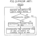
- Figure 1 is a block diagram of a conventional apparatus for controlling the iris; and Figure 2 is a flow chart showing the operational steps of the conventional apparatus shown in Figure 1.
- a data detector 12 senses a brightness of an input video signal input from an iris 11 (step 21).
- a controller 13 judges whether control of the iris 11 is needed (step 22). If control of the iris 11 is needed, the controller 13 calculates a control value, and outputs the control value to an iris controller 14 (step 23).
- the iris controller 14 controls the aperture size of the iris 11 by the control value from the controller 13 (step 24).
- the above method for controlling the iris uses a feedback method. The above operations are repeated until an output video signal having a correct brightness level has been achieved.
- the control of the iris restarts according to the varied brightness. Therefore some time is needed to output a video signal having a proper brightness, and a video signal having an improper brightness is generated until the iris has been completely controlled.
- a method for controlling an iris comprising calculating an amplification ratio for making an input video signal have a correct brightness level when control of the iris is needed, amplifing the input video signal by using the amplification ratio while controlling the iris, and outputting the input video signal with an amplification ratio of 1 without a change in level when iris control is not needed.
- the method when a distortion of the video signal might otherwise be generated to an abrupt increase in light intensity the method reduces a storage time of the light intensity by controlling a shutter speed, thereby preventing or reducing the distortion of the input video signal.
- an apparatus for controlling an iris which apparatus includes a data detector, a controller, and an iris controller using a feedback method and which further includes a buffer which stores an amplification ratio for making an input video signal have a proper brightness level when iris control is needed and stores the amplification ratio of 1 when the iris control is not needed, and a multiplier which amplifies the input video signal by the amplification ratio stored in the buffer.
- the apparatus for controlling the iris preferably prevents or reduces the distortion of the video signal by controlling a shutter speed when the intensity of light is abruptly increased.
- a method for controlling an iris according to a brightness variation comprising the steps of:
- said step of calculating the control value of the iris includes a step of multiplying the input video signal by the amplification ratio.
- the method may further comprise the steps of:
- Said light quantity may be determined as an abrupt increasing condition when the brightness of the input video signal is larger than the predetermined threshold value.
- the method further comprises the step of recovering the shutter speed to an original shutter speed after controlling the iris.
- an apparatus for controlling an iris according to a brightness variation comprising:
- Said controller preferably applies the amplification of 1 to the buffer when there is no need for controlling the iris.
- said controller determines the condition of an abrupt increase in light quantity when the brightness of the input signal is higher than a predetermined threshold value, and controls a shutter speed.
- Said controller preferably recovers the shutter speed to an original shutter speed after controlling the iris.
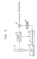
- an iris 31, a data detector 32, and an iris controller 34 have the same or similar functions as their equivalents in Figure 1.
- the apparatus shown in Figure 3 further includes a buffer 35 which stores an amplification ratio for making an input video signal having a proper brightness level when control of the iris is needed and stores the amplification ratio of 1 when control of the iris is not needed, and a multiplier 36 which amplifies the input video signal by the amplification ratio stored in the buffer 35.
- the controller 33 calculates a control value of the iris 31 when control of the iris is needed, and calculates the amplification ratio for making the input video signal have a proper brightness level, and outputs the amplification ratio to the buffer 35.
- the data detector 32 senses a brightness of the input video signal from the iris 31, and outputs the brightness signal to the controller 33 (step 41).
- the controller 33 judges whether control of the iris is needed (step 42).
- the controller 33 calculates the amplification ratio for making the video signal have a proper brightness level when control of the iris is needed (step 43).
- the amplification ratio from the controller 33 is stored in the buffer 35 (step 44).
- the controller 33 calculates the control value of the iris when control of the iris is needed (step 45).
- the iris controller 34 controls the aperture sie of the iris according to the control value calculated (step 46). After controlling the iris, the operation is fed back to step 41, so that the aforementioned steps are repeated.
- step 42 When the controller 33 judges there is no need to control the iris because the input video signal has a proper brightness level (step 42), the amplification ratio of 1 is stored in the buffer 35 (step 47). After storing the amplification ratio in the buffer 35, the operation is fed back to step 41, so that the aforementioned steps are repeated.
- the multiplier 36 amplifies the video signal from the data detector 32 by using the amplification ratio stored in the buffer 35. Therefore, the video signal amplified by the amplification ratio is generated while controlling the iris.
- the input video signal having the amplification ratio of 1 is output without a change when control of the iris is not needed.
- the video signal when control of the iris is needed because of an improper brightness of the input video signal, the video signal is amplified simultaneously with controlling the iris by a feedback method, thereby generating a video signal having a proper brightness.
- the input video signal already has the proper brightness (that is, when the input video signal essentially has a proper brightness or attains a proper brightness through a control of the iris), the input video signal is output without a change.
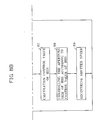
- Figure 5A shows a state before a control of the iris when the user moves from a light place to a dark place.
- the iris is slightly open in the light place having large quantities of light. After moving from the light place to the dark place having the small quantity of light, the iris is still only slightly open before the control of the iris.
- the input video signal has a low brightness level.
- the iris is controlled while the iris is slightly open, an overflow of the quantity of light does not occur in the CCD cell while controlling the iris.
- Figure 5B shows a condition after the control of the iris when the user moves from the light place to the dark place.
- the iris is widely open by controlling the iris, and attains more quantity of light.
- a magnitude of the brightness of the input video signal is controlled as shown in Figure 6B.
- Figure 5C shows a condition before the control of the iris when the user moves from the dark place to the light place.
- the iris is widely opened as it was in the dark place having the small quantity of light. After moving from the dark place to the light place, the iris is still widely open during the control of the iris. Accordingly, an overflow of the light quantity occurs at many photoelectric charges stored in the CCD cell, so that the input video signal is distorted as shown in Figure 6C.
- Another preferred embodiment of the present invention detects the quantity of light, and shortens the storage time of the photoelectric charge stored in the CCD cell by increasing a shutter speed when the sensed quantity of light is larger than a threshold value of overflow of the CCD cell, and thus prevents overflow of the CCD cell during iris control.
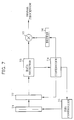
- FIG. 7 is a block diagram of the apparatus for controlling the iris in accordance with another preferred embodiment of the present invention. As shown in Figure 7, many elements of this preferred embodiment of the present invention are identical with those of Figure 3. However, a controller 74 further includes the steps of controlling a speed of a shutter 72.
- a data detector 73 senses a brightness of the input video signal from an iris 71, and outputs the brightness signal of the input video signal to the controller 74 (step 81).
- the controller 74 compares the brightness signal with a predetermined threshold value, judges whether a value of the brightness is higher than the threshold value (step 82).
- the threshold value is a maximum value of a brightness signal wherein the overflow of the CCD cell does not occur.
- the controller 74 controls the shutter 72 by calculating the shutter speed when the brightness value is higher than the threshold value (step 83). That is, a storage time of the quantity of light stored in the CCD cell is shortened by increasing the shutter speed, so that the overflow of the quantity of light does not occur in the CCD cell.
- the controller 74 judges the control of the iris when the brightness value is not beyond the threshold value (step 84), and calculates an amplification ratio for making a video signal have a proper brightness level when control of the iris is needed (step 85).
- a buffer 76 stores the amplification ratio (step 86).
- the controller 74 calculates a control value of the iris (step 87).
- the iris controller 75 controls the aperture size of the iris according to the control value of the iris (step 88). After the aperture size of the iris, a shutter speed is recovered by the controller 74 (step 89). After controlling the iris, the operation is fed back to step 81, so that the aforementioned steps are repeated.
- the controller 74 judges there is no need to control the iris because the input video signal has a proper brightness, the amplification ratio of 1 is stored in the buffer 76 (step 90). After storing the amplification ratio to the buffer 76, the operation is fed back to step 811, so that the aforementioned steps are repeated.
- the multiplier 77 amplifies the input video signal by the amplification ratio stored in the buffer 76. Therefore, the video signal amplified by the amplification ratio is output while controlling the iris.
- the input video signal having the amplification ratio of 1 is output without a change when there is no need for controlling the iris.
- the apparatus and the method for controlling the iris output a video signal which has a proper brightness during control of the iris by a feedback method by using both the buffer and the multiplier.
- embodiments of the present invention prevent or reduce the distortion of the input video signal byu controlling the shutter speed when the quantity of light is abruptly changed.
Landscapes
- Engineering & Computer Science (AREA)
- Multimedia (AREA)
- Signal Processing (AREA)
- Exposure Control For Cameras (AREA)
- Studio Devices (AREA)
- Diaphragms For Cameras (AREA)
Applications Claiming Priority (4)
| Application Number | Priority Date | Filing Date | Title |
|---|---|---|---|
| KR9526202 | 1995-08-23 | ||
| KR19950026202 | 1995-08-23 | ||
| KR9552937 | 1995-12-20 | ||
| KR1019950052937A KR100191308B1 (ko) | 1995-08-23 | 1995-12-20 | 휘도변화에 따른 조리개 조절방법 및 그 장치 |
Publications (3)
| Publication Number | Publication Date |
|---|---|
| EP0762743A2 true EP0762743A2 (de) | 1997-03-12 |
| EP0762743A3 EP0762743A3 (de) | 1998-01-07 |
| EP0762743B1 EP0762743B1 (de) | 2001-10-17 |
Family
ID=26631221
Family Applications (1)
| Application Number | Title | Priority Date | Filing Date |
|---|---|---|---|
| EP96306038A Expired - Lifetime EP0762743B1 (de) | 1995-08-23 | 1996-08-19 | Vorrichtung und Methode zur Regelung der Iris gemäss den Helligkeitsänderungen des Eingangsvideosignals |
Country Status (6)
| Country | Link |
|---|---|
| US (1) | US5923372A (de) |
| EP (1) | EP0762743B1 (de) |
| JP (1) | JP2954883B2 (de) |
| KR (1) | KR100191308B1 (de) |
| CN (1) | CN1151658A (de) |
| DE (1) | DE69615974T2 (de) |
Families Citing this family (7)
| Publication number | Priority date | Publication date | Assignee | Title |
|---|---|---|---|---|
| JP4181753B2 (ja) * | 2001-03-22 | 2008-11-19 | キヤノン株式会社 | 露出決定装置およびその露出決定装置を備えた撮像装置 |
| US6999126B2 (en) * | 2001-09-17 | 2006-02-14 | Mazzapica C Douglas | Method of eliminating hot spot in digital photograph |
| US7220006B2 (en) * | 2003-08-08 | 2007-05-22 | Allen Eddie E | Method and apparatus for increasing effective contrast ratio and brightness yields for digital light valve image projectors |
| US20090180080A1 (en) * | 2008-01-16 | 2009-07-16 | Oakley William S | Intra-Scene Dynamic Range Increase by Use of Programmed Multi-Step Filter |
| US8025416B2 (en) * | 2008-02-18 | 2011-09-27 | 3D4K Displays, Inc. | Integrated optical polarization combining prism for projection displays |
| US20120196271A1 (en) * | 2011-01-27 | 2012-08-02 | Pocared Diagnostics Ltd. | Iris Control System for Conducting the Identification of Bacteria in Biological Samples |
| KR102496066B1 (ko) * | 2021-04-08 | 2023-02-07 | 주식회사 더웨이브톡 | 수질 검사기 |
Family Cites Families (11)
| Publication number | Priority date | Publication date | Assignee | Title |
|---|---|---|---|---|
| JPH0239775B2 (ja) * | 1982-06-07 | 1990-09-07 | Copal Co Ltd | Shatsutaakinoojusurusaabojidoshiborisochi |
| JPS61182163A (ja) * | 1985-02-06 | 1986-08-14 | Fujitsu Ltd | プログラム拡張方式 |
| JPS62288818A (ja) * | 1986-06-06 | 1987-12-15 | Matsushita Electric Ind Co Ltd | シヤツタ速度自動調節装置 |
| JP2712167B2 (ja) * | 1987-02-19 | 1998-02-10 | ソニー株式会社 | 撮像装置のオートアイリス回路 |
| US4780766A (en) * | 1987-05-29 | 1988-10-25 | Eastman Kodak Company | Still video camera having effective imager sensitivity optimized for electronic preview |
| JPH03127035A (ja) * | 1989-10-13 | 1991-05-30 | Matsushita Electric Ind Co Ltd | シャッター装置 |
| KR920011063B1 (ko) * | 1990-12-31 | 1992-12-26 | 삼성전자 주식회사 | 카메라의 자동이득 제어회로 |
| US5293241A (en) * | 1991-04-02 | 1994-03-08 | Gold Star Co., Ltd. | Method and circuit for controlling opening/closing of a camcorder iris diaphragm |
| US5455685A (en) * | 1991-09-04 | 1995-10-03 | Fuji Photo Film Co., Ltd. | Video camera exposure control apparatus for controlling iris diaphragm and automatic gain control operating speed |
| JP3411931B2 (ja) * | 1993-04-26 | 2003-06-03 | 富士写真フイルム株式会社 | 撮像装置および撮像方法 |
| KR100396203B1 (ko) * | 1993-06-17 | 2003-12-31 | 소니 가부시끼 가이샤 | 노광장치및방법,그노광장치를가지는비디오카메라 |
-
1995
- 1995-12-20 KR KR1019950052937A patent/KR100191308B1/ko not_active Expired - Fee Related
-
1996
- 1996-08-19 DE DE69615974T patent/DE69615974T2/de not_active Expired - Lifetime
- 1996-08-19 EP EP96306038A patent/EP0762743B1/de not_active Expired - Lifetime
- 1996-08-20 JP JP8218833A patent/JP2954883B2/ja not_active Expired - Fee Related
- 1996-08-23 CN CN96111491A patent/CN1151658A/zh active Pending
- 1996-08-23 US US08/702,214 patent/US5923372A/en not_active Expired - Lifetime
Also Published As
| Publication number | Publication date |
|---|---|
| DE69615974D1 (de) | 2001-11-22 |
| DE69615974T2 (de) | 2002-04-25 |
| JP2954883B2 (ja) | 1999-09-27 |
| JPH09166806A (ja) | 1997-06-24 |
| KR970014150A (ko) | 1997-03-29 |
| US5923372A (en) | 1999-07-13 |
| EP0762743B1 (de) | 2001-10-17 |
| CN1151658A (zh) | 1997-06-11 |
| KR100191308B1 (ko) | 1999-06-15 |
| EP0762743A3 (de) | 1998-01-07 |
Similar Documents
| Publication | Publication Date | Title |
|---|---|---|
| AU641320B2 (en) | Video signal gradation corrector | |
| KR100396203B1 (ko) | 노광장치및방법,그노광장치를가지는비디오카메라 | |
| CZ294352B6 (cs) | Korekční zařízení pro korekci tónu video signálu | |
| EP0762743A2 (de) | Vorrichtung und Methode zur Regelung der Iris gemäss den Helligkeitsänderungen des Eingangsvideosignals | |
| US20050190272A1 (en) | Image signal processor | |
| US8411163B2 (en) | Auto exposure controlling device and method | |
| JP2798800B2 (ja) | テレビジョン受像機の調整方法 | |
| US6567124B1 (en) | Electronic image processing technique for achieving enhanced image detail | |
| US5905533A (en) | Image processing apparatus | |
| JPH0622208A (ja) | ビデオカメラの自動露出制御装置 | |
| US5534920A (en) | Viewfinder brightness control circuit for a camcorder employing iris output voltage and method therefor | |
| JPH04340875A (ja) | 撮像装置 | |
| JP4971746B2 (ja) | 撮像装置、撮像装置の制御方法、及びコンピュータプログラム | |
| JP2578591B2 (ja) | 自動利得制御回路 | |
| KR200333736Y1 (ko) | 역광 보정 기능을 가지는 조리개 구동 회로 | |
| JPH05336436A (ja) | 自動利得制御装置 | |
| JPH0869550A (ja) | 光学センサ出力の自動補正装置 | |
| KR0178722B1 (ko) | 시시디카메라의 다이내믹 영역 확장방법 및 장치 | |
| JP2002369003A (ja) | 画像処理回路および画像処理方法 | |
| KR0159664B1 (ko) | 카메라시스템에 있어서 역광 보정시의 윈도우펄스 제어방법 | |
| JPH0937143A (ja) | 撮像装置 | |
| JPH04345280A (ja) | ビデオカメラの露光制御装置 | |
| JPH06169427A (ja) | テレビジョンカメラのオートアイリス制御システム | |
| JPH0723281A (ja) | 逆光補正装置及びそれを用いた撮像装置 | |
| JPH0738802A (ja) | 撮像装置 |
Legal Events
| Date | Code | Title | Description |
|---|---|---|---|
| PUAI | Public reference made under article 153(3) epc to a published international application that has entered the european phase |
Free format text: ORIGINAL CODE: 0009012 |
|
| 17P | Request for examination filed |
Effective date: 19960829 |
|
| AK | Designated contracting states |
Kind code of ref document: A2 Designated state(s): DE FR GB NL |
|
| PUAL | Search report despatched |
Free format text: ORIGINAL CODE: 0009013 |
|
| AK | Designated contracting states |
Kind code of ref document: A3 Designated state(s): DE FR GB NL |
|
| 17Q | First examination report despatched |
Effective date: 20000210 |
|
| GRAG | Despatch of communication of intention to grant |
Free format text: ORIGINAL CODE: EPIDOS AGRA |
|
| GRAG | Despatch of communication of intention to grant |
Free format text: ORIGINAL CODE: EPIDOS AGRA |
|
| GRAH | Despatch of communication of intention to grant a patent |
Free format text: ORIGINAL CODE: EPIDOS IGRA |
|
| GRAH | Despatch of communication of intention to grant a patent |
Free format text: ORIGINAL CODE: EPIDOS IGRA |
|
| GRAA | (expected) grant |
Free format text: ORIGINAL CODE: 0009210 |
|
| AK | Designated contracting states |
Kind code of ref document: B1 Designated state(s): DE FR GB NL |
|
| REF | Corresponds to: |
Ref document number: 69615974 Country of ref document: DE Date of ref document: 20011122 |
|
| REG | Reference to a national code |
Ref country code: GB Ref legal event code: IF02 |
|
| ET | Fr: translation filed | ||
| PLBE | No opposition filed within time limit |
Free format text: ORIGINAL CODE: 0009261 |
|
| STAA | Information on the status of an ep patent application or granted ep patent |
Free format text: STATUS: NO OPPOSITION FILED WITHIN TIME LIMIT |
|
| 26N | No opposition filed | ||
| PGFP | Annual fee paid to national office [announced via postgrant information from national office to epo] |
Ref country code: NL Payment date: 20140722 Year of fee payment: 19 Ref country code: DE Payment date: 20140723 Year of fee payment: 19 |
|
| PGFP | Annual fee paid to national office [announced via postgrant information from national office to epo] |
Ref country code: GB Payment date: 20140723 Year of fee payment: 19 Ref country code: FR Payment date: 20140724 Year of fee payment: 19 |
|
| REG | Reference to a national code |
Ref country code: DE Ref legal event code: R119 Ref document number: 69615974 Country of ref document: DE |
|
| GBPC | Gb: european patent ceased through non-payment of renewal fee |
Effective date: 20150819 |
|
| REG | Reference to a national code |
Ref country code: NL Ref legal event code: MM Effective date: 20150901 |
|
| REG | Reference to a national code |
Ref country code: FR Ref legal event code: ST Effective date: 20160429 |
|
| PG25 | Lapsed in a contracting state [announced via postgrant information from national office to epo] |
Ref country code: NL Free format text: LAPSE BECAUSE OF NON-PAYMENT OF DUE FEES Effective date: 20150901 |
|
| PG25 | Lapsed in a contracting state [announced via postgrant information from national office to epo] |
Ref country code: GB Free format text: LAPSE BECAUSE OF NON-PAYMENT OF DUE FEES Effective date: 20150819 Ref country code: DE Free format text: LAPSE BECAUSE OF NON-PAYMENT OF DUE FEES Effective date: 20160301 |
|
| PG25 | Lapsed in a contracting state [announced via postgrant information from national office to epo] |
Ref country code: FR Free format text: LAPSE BECAUSE OF NON-PAYMENT OF DUE FEES Effective date: 20150831 |