EP0765747A1 - Dispositif de revêtement et méthode pour délivrer un liquide, et pour vider et nettoyer un dispositif de revêtement - Google Patents
Dispositif de revêtement et méthode pour délivrer un liquide, et pour vider et nettoyer un dispositif de revêtement Download PDFInfo
- Publication number
- EP0765747A1 EP0765747A1 EP96112858A EP96112858A EP0765747A1 EP 0765747 A1 EP0765747 A1 EP 0765747A1 EP 96112858 A EP96112858 A EP 96112858A EP 96112858 A EP96112858 A EP 96112858A EP 0765747 A1 EP0765747 A1 EP 0765747A1
- Authority
- EP
- European Patent Office
- Prior art keywords
- liquid
- pump means
- port
- return
- applicator
- Prior art date
- Legal status (The legal status is an assumption and is not a legal conclusion. Google has not performed a legal analysis and makes no representation as to the accuracy of the status listed.)
- Granted
Links
- 239000007788 liquid Substances 0.000 title claims abstract description 106
- 239000011248 coating agent Substances 0.000 title claims abstract description 49
- 238000000576 coating method Methods 0.000 title claims abstract description 49
- 238000004140 cleaning Methods 0.000 title claims abstract description 31
- 238000000034 method Methods 0.000 title claims description 8
- 238000005086 pumping Methods 0.000 claims abstract description 35
- 239000000758 substrate Substances 0.000 claims abstract description 14
- 238000004891 communication Methods 0.000 claims description 10
- 230000002572 peristaltic effect Effects 0.000 claims description 2
- 239000000976 ink Substances 0.000 abstract description 28
- 238000005406 washing Methods 0.000 abstract description 8
- 239000008199 coating composition Substances 0.000 abstract description 5
- 239000000203 mixture Substances 0.000 abstract description 2
- 238000007774 anilox coating Methods 0.000 description 4
- 239000002699 waste material Substances 0.000 description 4
- 230000005484 gravity Effects 0.000 description 2
- 238000012163 sequencing technique Methods 0.000 description 2
- 239000002904 solvent Substances 0.000 description 2
- XLYOFNOQVPJJNP-UHFFFAOYSA-N water Substances O XLYOFNOQVPJJNP-UHFFFAOYSA-N 0.000 description 2
- 239000003086 colorant Substances 0.000 description 1
- 239000000356 contaminant Substances 0.000 description 1
- 239000003599 detergent Substances 0.000 description 1
- 230000000694 effects Effects 0.000 description 1
- 239000012530 fluid Substances 0.000 description 1
- 238000012986 modification Methods 0.000 description 1
- 230000004048 modification Effects 0.000 description 1
- 230000000750 progressive effect Effects 0.000 description 1
- 230000010349 pulsation Effects 0.000 description 1
Images

Classifications
-
- B—PERFORMING OPERATIONS; TRANSPORTING
- B41—PRINTING; LINING MACHINES; TYPEWRITERS; STAMPS
- B41F—PRINTING MACHINES OR PRESSES
- B41F31/00—Inking arrangements or devices
- B41F31/02—Ducts, containers, supply or metering devices
- B41F31/08—Ducts, containers, supply or metering devices with ink ejecting means, e.g. pumps, nozzles
Definitions
- the present invention relates to an apparatus for coating substrates. More particularly the invention pertains to an improved coating apparatus which uniformly applies inks and other compositions onto substrates.
- the apparatus has the facility of an automated washing cycle for cleanup between different coating compositions.
- inks or other coating compositions it is known in the art of flexographic printing to continuously apply inks or other coating compositions to paper or other substrates.
- ink is applied to the surface of an anilox roller through an ink fountain having doctor blades.
- Typical ink fountains are described in U.S. patents 5,410,961; 5,010,817, and 4,527,479 which are incorporated herein by reference.
- ink or other coating solutions may not be uniformly supplied to it.
- an ink is supplied to a fountain either by the action of gravity or a pump. Excess ink is likewise removed from a fountain either by gravity or a pump.
- U.S. patent 5,213,044 shows a coating apparatus which uses a single pump which is capable of reversing fluid flow direction.
- U.S. patent 5,367,982 shows a circulation system for a fountain employing both fed and return line pumps. While the pumps adjust the flow rate of the liquid, the pumps are not independently variable. This is disadvantageous since pulsations and hence uneven flow can be caused in improperly adjusted flow lines.
- U.S. patent 4,643,124 shows another liquid coating supply system where the supply and return pumps act in unison by an air cylinder and are not independently controllable either in speed or magnitude of pumping strokes. This invention provides a coating system having supply and return pumps which are independently controllable in speed and/or magnitude of pumping strokes. This allows improved control of coating liquid flow as well as flow line pressure control for different viscosity liquids.
- This invention therefore not only provides a system for circulating a liquid coating or ink through a fountain coater but also including means for automatically draining and washing the fountain and its liquid circulation system.
- the fountain When the fountain is to remain idle for an extended period, at the end of the work day, or between color changes the liquid must be drained from the fountain, and all fountain parts and flow lines must be thoroughly cleaned using appropriate solutions.
- the supply lines, return lines and the fountain must be flushed and hand cleaned.
- the coating rollers and reservoir pan must also be cleaned manually. A substantial amount of press downtime is involved during the manual cleaning of the coater components. Manual cleaning requires that the coater be removed from the press to provide clean-up access to internal components.
- the present invention provides an improved coating assembly which performs conventional coating operations, and which is automatically sequenced through cleaning cycles while the coater remains attached to the press, and does not require disassembly, removal and reassembly for manual cleaning. Cleaning operations are performed more completely and more thoroughly than can be achieved by conventional manual cleaning methods.
- the same pumps are used for circulating a cleaning solution as well as for circulating the coating liquid.
- the supply and return lines, valves and pumps which circulate the coating liquid and cleaning solution all are drained and cleaned simultaneously with the cleaning of the fountain and anilox roller, thus preventing the progressive build-up of contaminants which occur in the coating components of such systems.
- the valving, pumping and liquid supply reservoir and waste storage handle the circulation of both the coating liquid and the cleaning solution.
- the assembly employs three-port control valves to effect the different operating modes of coating, washing and draining which may be actuated automatically under the control of automatic sequencing means such as a programmable logic controller.
- the invention provides a coating apparatus comprising:
- the invention also provides a method of dispensing a liquid to a substrate which comprises providing the above coating apparatus; causing the flow controller means to independently adjust each of the supply pump means and the return pump means such that a return pumping force is applied and maintained which is greater than an applied supply pumping force; and automechanically adjusting the first, second, third and fourth three-port valves to sequentially cause the apparatus to draw a liquid from a reservoir and direct the liquid to the applicator, drain the liquid from the apparatus, circulate a cleaning solution about the apparatus and drain the cleaning solution from the apparatus.
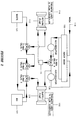
- Figure 1 shows a schematic representation of one embodiment of the coating apparatus arrangement according to the invention.
- Figure 2 shows a schematic representation of one embodiment of the coating apparatus arrangement according to the invention showing valve positions.
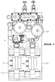
- Figure 3 shows a top view of an apparatus which embodies the invention.
- FIG. 1 schematically depicts one embodiment of the coating apparatus arrangement according to the invention.
- the coating apparatus of the invention employs applicator, fountain assembly or inker body means 100 capable of applying a liquid from a reserve on the applicator to a substrate.
- An applicator particularly useful for this invention is the fountain assembly which is described in U.S. patent 5,410,961.
- This fountain assembly is alternatively provided with an ink, a coating composition or a cleaning solution via supply lines to a manifold internal to the fountain.
- ink from a reservoir 102 is connected via suitable tubing to a supply pump 104.
- the supply pump may be any suitable pumping means such as a gear pump, peristaltic pump, diaphragm pump or the like as are well known in the art.
- the pump action is preferably controlled in pumping magnitude and speed by a flow controller including a programmable logic controller, not shown, via pneumatic lines 106.
- the supply pump 104 pumps ink or other desired solution to a liquid accumulator 108 which may be in the form of a suitable liquid collection vessel.
- the accumulator serves to dampen liquid supply surges to the inker body and aids in the provision of a more uniform source of liquid to the inker body.
- the inker body itself is well known in the art.
- An important feature of the invention is a liquid return arrangement which serves to provide a more uniform supply and pressure of liquid throughout the apparatus.
- Inker bodies comprise a liquid reserve. That is, several liters of a liquid, such as ink fill a chamber within the inker body.
- This chamber is continually refilled by the supply pump from the ink reservoir 102.
- liquid is withdrawn from the inker body by a return system. Withdrawn liquid flows from the inker body 100 to a drain accumulator 110. Such liquid is drawn by a return pump 112 and excess ink returned to ink reservoir 102.
- Return pump 112 is likewise controlled by the flow controller, including the programmable logic controller, not shown, via pneumatic lines 114.
- An important feature of the invention is that the supply pump 104 and return pump 112 be operated such that the return pumping force applied and maintained is greater the applied supply pumping force.
- the flow controller means including appropriate pump motors, is capable of independently controlling the pumping speed and pumping force magnitude of the each of the supply pump means and the return pump means.
- An air check valve 116 is preferably positioned between the applicator and the return pump to prevent a vacuum from building-up in the return lines.
- Figure 2 shows another preferred embodiment of the invention including an arrangement of several three-port valves.
- it is necessary to clean the inker body and supply and return lines of the apparatus with some degree of frequency.
- ink is normally drawn from and returned to reservoir 102 by the supply and return pumps 104 and 112.
- This invention provides automechanically controlled alternate inking and washing cycles.
- ink is sequentially applied by the inker body, ink is drained from the overall apparatus, cleaning solution flushes the apparatus parts and is drained to waste, and finally a new ink supply is introduced.
- Figure 2 shows the positioning of the three-port valves.
- Such three port valves are well known in the art and widely commercially available.
- Three-port valve 3 has a first port connected to the reservoir 102, a second port connected to the supply pump means 104 and a third port connected to a port of three-port valve 2.
- Three-port valve 2 has a first port connected to three-port valve 1, a second port connected to the reservoir 102 and a third port connected to a port of three-port valve 3.
- Three-port valve 1 has a first port connected to a port of three-port valve 2, a second port connected to a waste drain 120 and a third port connected to the return pump 112.
- Three-port valve 4 has a first port connected to the return pump 112, a second port connected to the return liquid accumulator 110 and third port connected to an output of the supply pump 104 and an input of the supply liquid accumulator 108.
- cleaning solution enters the apparatus via line 118 and drains to waste collector 120.
- the cleaning solution may comprise water alone, a detergent or any other appropriate solvent.
- the inker body preferably has washing nozzles which distribute the cleaning solution onto the applicator chamber, doctor blades, anilox rollers and other associated parts.
- each of the ports of the four three-port valves are labelled A through K.
- Table 1 indicates the position of valves 1 through 4, supply and return pump action, cleaning solution supply and draining for a preferred automatic washing sequence.
- the operation of all of these parts and the timing of each step is preferably automatically configured and controlled by a programmable logic controller.
- the duration of each step lasts for from a few seconds to a few minutes depending on the nature of the liquid applied and the cleaning solution used. The duration of each step can be easily determined by those skilled in the art under the particular circumstances of operation.
- valve port positions are: Valve 1 Valve 2 Valve 3 Valve 4 Open A, C D, E H, I K, L Closed B F G J
- the pump speeds and drain valves are as follows: Supply Pump Speed Return Pump Speed Drain Valves Establish Ink Circuit High High Open Prime Inker Low Low Closed Print Operator Choice Determined By Supply Speed Closed
- Automatic control and sequencing removes the burden of determining the length of the operating cycle from the press operator, and permits the press operator to attend to other duties during automatic was and drain cycles.
- all the press operator is required to do to initiate a cleaning cycle is to momentarily depress an actuator which causes the operation to advance from the printing mode to the drain mode, to the wash mode and finally turning off the pumps to a system off position upon conclusion of the cycles.
- the operator may then refill the reservoir with coating liquid, and restart the coating of operation.
- cleaning solution is circulated through the applicator which cleans the anilox roller at the same time the applicator is cleaned.
- Figure 3 shows a top view of an apparatus which embodies the invention. Shown are supply and return pumps 104 and 112, pneumatic lines 106 and 114, accumulators 108 and 110, three-port valves 1, 2, 3, and 4, ink supply and return lines and suitable tubing and connectors.
- the coating circulation and wash-up system described above provides the advantages of the invention as stated. Regardless of whether the assembly is under remote control by manual or fully automatic, the requirement of removing the coater from the press for cleaning is completely eliminated. It will be appreciated that the coating circulation and wash-up system of the present invention may be retrofit onto existing coating equipment without modifying existing press or coater equipment. While a particular form of the present invention has been illustrated and described, it should be apparent that variations and modifications may be made therein without departing from the spirit and scope of the invention as set forth in the appended claims.
Landscapes
- Coating Apparatus (AREA)
- Application Of Or Painting With Fluid Materials (AREA)
Applications Claiming Priority (2)
| Application Number | Priority Date | Filing Date | Title |
|---|---|---|---|
| US08/519,107 US5683508A (en) | 1995-08-25 | 1995-08-25 | Coating apparatus and method for dispensing a liquid, and draining and cleaning a coating apparatus |
| US519107 | 1995-08-25 |
Publications (3)
| Publication Number | Publication Date |
|---|---|
| EP0765747A1 true EP0765747A1 (fr) | 1997-04-02 |
| EP0765747B1 EP0765747B1 (fr) | 1999-03-17 |
| EP0765747B2 EP0765747B2 (fr) | 2002-11-27 |
Family
ID=24066861
Family Applications (1)
| Application Number | Title | Priority Date | Filing Date |
|---|---|---|---|
| EP96112858A Expired - Lifetime EP0765747B2 (fr) | 1995-08-25 | 1996-08-09 | Dispositif de revêtement et méthode pour délivrer un liquide, et pour vider et nettoyer un dispositif de revêtement |
Country Status (3)
| Country | Link |
|---|---|
| US (1) | US5683508A (fr) |
| EP (1) | EP0765747B2 (fr) |
| DE (1) | DE69601766T3 (fr) |
Cited By (5)
| Publication number | Priority date | Publication date | Assignee | Title |
|---|---|---|---|---|
| EP0958920A1 (fr) * | 1998-05-22 | 1999-11-24 | Fischer & Krecke Gmbh & Co. | Machine à imprimer |
| EP1022137A1 (fr) * | 1998-12-22 | 2000-07-26 | Heidelberger Druckmaschinen Aktiengesellschaft | Dosification numérique d'encre |
| WO2003103964A3 (fr) * | 2002-06-10 | 2004-07-01 | Windmoeller & Hoelscher | Procede et dispositif permettant d'amener de l'encre d'imprimerie dans un dispositif de racle d'un mecanisme d'encrage d'une presse rotative ainsi que d'evacuer cette encre de ce dispositif et/ou de nettoyer ce dispositif de racle |
| EP1719621A1 (fr) * | 2005-05-02 | 2006-11-08 | Oxy-Dry Maschinen GmbH | Système de nettoyage pour les surfaces des cylindres d'une machine d'impression |
| WO2010034660A1 (fr) * | 2008-09-29 | 2010-04-01 | Windmöller & Hölscher Kg | Dispositif et procédé d’alimentation d’un mécanisme d’encrage ou d’impression d’une machine à imprimer en encre d’imprimerie ou un autre liquide |
Families Citing this family (16)
| Publication number | Priority date | Publication date | Assignee | Title |
|---|---|---|---|---|
| US6395088B1 (en) * | 1999-06-30 | 2002-05-28 | Gaston Systems, Inc. | Apparatus for applying foamed coating material to a traveling textile substrate |
| US6576059B2 (en) * | 1999-11-22 | 2003-06-10 | Harris & Bruno Company, Inc. | Chambered doctor blade system for water-based and UV-based coatings |
| US6383296B1 (en) | 1999-11-22 | 2002-05-07 | Harris & Bruno Machine Co. | Chambered doctor blade with automatic cleanup and ink replacement |
| DE10246946B4 (de) * | 2001-11-07 | 2013-06-13 | Heidelberger Druckmaschinen Ag | Einrichtung zum Beschichten von Bedruckstoffen in einer Druckmaschine |
| ITGE20020033A1 (it) * | 2002-04-24 | 2003-10-24 | Schiavi Spa | Metodo di lavaggio automatico del circuito di inchiostrazione nelle macchine da stampa rotative, ed impianto per l'attuazione di detto metod |
| AU2003291545A1 (en) * | 2002-11-15 | 2004-06-15 | Graymills Corporation | System and method for delivering and flushing ink and other liquids in a printing press |
| US20060080847A1 (en) * | 2004-10-18 | 2006-04-20 | Garry Tsaur | Line marking means |
| WO2006043944A1 (fr) * | 2004-10-18 | 2006-04-27 | Garry Tsaur | Dispositif de marquage de lignes |
| US7431771B2 (en) * | 2004-11-12 | 2008-10-07 | Gaston Systems, Inc. | Apparatus and method for applying a foamed composition to a dimensionally unstable traveling substrate |
| EP1869324B1 (fr) * | 2005-04-07 | 2012-03-14 | Marion H. Bobo | Tete de pompe peristaltique |
| US7810674B2 (en) * | 2005-07-26 | 2010-10-12 | Millipore Corporation | Liquid dispensing system with enhanced mixing |
| US7950547B2 (en) * | 2006-01-12 | 2011-05-31 | Millipore Corporation | Reservoir for liquid dispensing system with enhanced mixing |
| US20090291217A1 (en) * | 2008-05-21 | 2009-11-26 | Harris & Bruno Machine Co., Inc. | Doctor blade supply system with intelligent viscosity logic |
| DE112013001593B4 (de) * | 2012-03-22 | 2022-11-10 | Kabushiki Kaisha Yaskawa Denki | Applikationsvorrichtung |
| US9180674B2 (en) | 2013-02-08 | 2015-11-10 | R.R. Donnelley & Sons Company | System and method for supplying ink to an inkjet cartridge |
| CN207291314U (zh) | 2016-05-09 | 2018-05-01 | R.R.当纳利父子公司 | 油墨供应单元 |
Citations (2)
| Publication number | Priority date | Publication date | Assignee | Title |
|---|---|---|---|---|
| DE453028C (de) * | 1927-11-26 | Friedrich Knacke | Verfahren und Vorrichtung zum Erhalten eines gleichmaessigen Farbstands in den Farbkaesten von Druckmaschinen, insbesondere Rotationsdruckmaschinen | |
| US5335596A (en) * | 1991-08-30 | 1994-08-09 | Howard W. DeMoore | Coating apparatus for sheet-fed, offset rotary printing presses |
Family Cites Families (18)
| Publication number | Priority date | Publication date | Assignee | Title |
|---|---|---|---|---|
| US3974768A (en) * | 1975-03-31 | 1976-08-17 | Molins Machine Company, Inc. | Dual ink circulation and wash-up system for a press |
| US4527479A (en) * | 1981-07-31 | 1985-07-09 | Dahlgren Harold P | Ink removal, circulating and distributing system |
| JPS60196348A (ja) * | 1984-03-17 | 1985-10-04 | Isowa Ind Co | インキ転移機構のインキ回収洗浄装置 |
| US4643124A (en) * | 1985-05-13 | 1987-02-17 | Ryco Graphic Manufacturing, Inc. | Liquid coating supply system for a printing press blanket coater |
| JPS62201669A (ja) * | 1986-03-01 | 1987-09-05 | Dainippon Screen Mfg Co Ltd | ロ−ルコ−タの制御方法およびロ−ルコ−タ |
| US4822647A (en) * | 1986-04-23 | 1989-04-18 | Honda Giken Kogyo Kabushiki Kaisha | Coating agent to coating robot, including a method and arrangement for protecting the apparatus from damage due to improper pressures in a supply line |
| US4822547A (en) † | 1987-04-06 | 1989-04-18 | Shell Oil Company | Process for the extrusion of compositions comprising polypropylene, polyvinyl alcohol and a polypropylene-polyvinyl alcohol adhesive |
| US5005478A (en) * | 1987-12-16 | 1991-04-09 | Precision Engineered Systems Inc. | Blanket wash system with sub-ambient pressure circulation |
| DE3814049A1 (de) * | 1988-04-26 | 1989-11-09 | Koenig & Bauer Ag | Verfahren und einrichtung fuer den flexo-druck |
| FR2648393B2 (fr) * | 1988-07-07 | 1991-09-20 | Sarda Jean | Perfectionnements apportes aux centrales de nettoyage et traitement pour l'entretien des presses a imprimer |
| EP0368485A3 (fr) * | 1988-10-31 | 1991-01-30 | Seiken Graphics, Inc. | Impression lithographique |
| US5330576A (en) * | 1990-04-26 | 1994-07-19 | Baldwin-Gegenheimer Gmbh | Recirculating coating liquid supply system with viscosity regulation |
| US5273583A (en) * | 1990-07-02 | 1993-12-28 | Xerox Corporation | Fabrication of electrophotographic imaging members |
| US5213044A (en) * | 1990-11-30 | 1993-05-25 | Como Technologies, Incorporated | Method and apparatus for use in printing |
| US5207159A (en) * | 1991-08-30 | 1993-05-04 | Howard W. DeMoore | Coating apparatus for sheet-fed, offset rotary printing presses |
| US5410961A (en) * | 1992-12-30 | 1995-05-02 | Fit Group, Inc. | Fountain assembly |
| US5367982A (en) * | 1993-02-25 | 1994-11-29 | Howard W. DeMoore | Automatic coating circulation and wash-up system for printing presses |
| US5425809A (en) * | 1993-06-17 | 1995-06-20 | Howard W. DeMoore | Anilox coater with brush |
-
1995
- 1995-08-25 US US08/519,107 patent/US5683508A/en not_active Expired - Fee Related
-
1996
- 1996-08-09 EP EP96112858A patent/EP0765747B2/fr not_active Expired - Lifetime
- 1996-08-09 DE DE69601766T patent/DE69601766T3/de not_active Expired - Fee Related
Patent Citations (2)
| Publication number | Priority date | Publication date | Assignee | Title |
|---|---|---|---|---|
| DE453028C (de) * | 1927-11-26 | Friedrich Knacke | Verfahren und Vorrichtung zum Erhalten eines gleichmaessigen Farbstands in den Farbkaesten von Druckmaschinen, insbesondere Rotationsdruckmaschinen | |
| US5335596A (en) * | 1991-08-30 | 1994-08-09 | Howard W. DeMoore | Coating apparatus for sheet-fed, offset rotary printing presses |
Cited By (6)
| Publication number | Priority date | Publication date | Assignee | Title |
|---|---|---|---|---|
| EP0958920A1 (fr) * | 1998-05-22 | 1999-11-24 | Fischer & Krecke Gmbh & Co. | Machine à imprimer |
| EP1022137A1 (fr) * | 1998-12-22 | 2000-07-26 | Heidelberger Druckmaschinen Aktiengesellschaft | Dosification numérique d'encre |
| WO2003103964A3 (fr) * | 2002-06-10 | 2004-07-01 | Windmoeller & Hoelscher | Procede et dispositif permettant d'amener de l'encre d'imprimerie dans un dispositif de racle d'un mecanisme d'encrage d'une presse rotative ainsi que d'evacuer cette encre de ce dispositif et/ou de nettoyer ce dispositif de racle |
| EP1719621A1 (fr) * | 2005-05-02 | 2006-11-08 | Oxy-Dry Maschinen GmbH | Système de nettoyage pour les surfaces des cylindres d'une machine d'impression |
| US7530307B2 (en) | 2005-05-02 | 2009-05-12 | Baldwin Oxy-Dry Gmbh | Cleaning system for cylinder surfaces of a printing machine |
| WO2010034660A1 (fr) * | 2008-09-29 | 2010-04-01 | Windmöller & Hölscher Kg | Dispositif et procédé d’alimentation d’un mécanisme d’encrage ou d’impression d’une machine à imprimer en encre d’imprimerie ou un autre liquide |
Also Published As
| Publication number | Publication date |
|---|---|
| DE69601766T3 (de) | 2003-05-28 |
| EP0765747B2 (fr) | 2002-11-27 |
| US5683508A (en) | 1997-11-04 |
| DE69601766D1 (de) | 1999-04-22 |
| DE69601766T2 (de) | 1999-09-02 |
| EP0765747B1 (fr) | 1999-03-17 |
Similar Documents
| Publication | Publication Date | Title |
|---|---|---|
| EP0765747B1 (fr) | Dispositif de revêtement et méthode pour délivrer un liquide, et pour vider et nettoyer un dispositif de revêtement | |
| CA2097378C (fr) | Dispositif automatique pour la circulation d'un revetement liquide et pour le lavage d'une presse a imprimer | |
| US6576059B2 (en) | Chambered doctor blade system for water-based and UV-based coatings | |
| CN1078533C (zh) | 轮转印刷机油墨机组刮墨装置的清洗方法和设备 | |
| US4497250A (en) | Ink Fountain | |
| US5915302A (en) | Printer ink exchange apparatus | |
| AU736068B2 (en) | A method and a pumping unit for supplying printing ink and cleaning liquid to a printing unit | |
| US20090288598A1 (en) | Doctor blade supply system with intelligent viscosity logic | |
| JPS61206656A (ja) | オフセツト輪転印刷機におけるゴムブランケツトの洗浄装置 | |
| US6383296B1 (en) | Chambered doctor blade with automatic cleanup and ink replacement | |
| EP0739729B1 (fr) | Appareil pour échanger l'encre d'une machine à imprimer | |
| JP2627865B2 (ja) | 輪転印刷機のインク供給及び洗浄装置 | |
| US20020073864A1 (en) | Flexographic printing press with device for washing the back-pressure cylinder | |
| CN214395866U (zh) | 一种凹版印刷机的供墨机构 | |
| JP3392548B2 (ja) | 印刷機あるいは塗工機のデッキを洗浄するための装置と方法 | |
| JP3564265B2 (ja) | フレキソ印刷機 | |
| US20090291217A1 (en) | Doctor blade supply system with intelligent viscosity logic | |
| JPS61144354A (ja) | 印刷機におけるロ−ラ洗浄装置 | |
| DE4438043B4 (de) | Verfahren zur Reinigung eines Lackiersystems | |
| EP3807091A1 (fr) | Système d'encrage pour une presse à rotogravure présentant des configurations optimales pour plusieurs types d'encre | |
| JPH05286121A (ja) | 印刷用版面へのインク供給装置 | |
| JP2002321341A (ja) | 輪転印刷機 | |
| EP1206324A1 (fr) | Dispositif pour l'equilibrage de temperatures de milieux d'enduction | |
| JPH0272957A (ja) | 印刷機のメンテナンス用洗浄及び処理装置 | |
| WO2019238200A1 (fr) | Cartouche d'encrage pour une presse à rotogravure présentant des configurations optimales pour plusieurs types d'encre |
Legal Events
| Date | Code | Title | Description |
|---|---|---|---|
| PUAI | Public reference made under article 153(3) epc to a published international application that has entered the european phase |
Free format text: ORIGINAL CODE: 0009012 |
|
| AK | Designated contracting states |
Kind code of ref document: A1 Designated state(s): CH DE FR GB IT LI |
|
| 17P | Request for examination filed |
Effective date: 19970722 |
|
| GRAG | Despatch of communication of intention to grant |
Free format text: ORIGINAL CODE: EPIDOS AGRA |
|
| 17Q | First examination report despatched |
Effective date: 19980706 |
|
| GRAG | Despatch of communication of intention to grant |
Free format text: ORIGINAL CODE: EPIDOS AGRA |
|
| GRAH | Despatch of communication of intention to grant a patent |
Free format text: ORIGINAL CODE: EPIDOS IGRA |
|
| GRAH | Despatch of communication of intention to grant a patent |
Free format text: ORIGINAL CODE: EPIDOS IGRA |
|
| GRAA | (expected) grant |
Free format text: ORIGINAL CODE: 0009210 |
|
| AK | Designated contracting states |
Kind code of ref document: B1 Designated state(s): CH DE FR GB IT LI |
|
| REG | Reference to a national code |
Ref country code: CH Ref legal event code: EP |
|
| REF | Corresponds to: |
Ref document number: 69601766 Country of ref document: DE Date of ref document: 19990422 |
|
| REG | Reference to a national code |
Ref country code: CH Ref legal event code: NV Representative=s name: E. BLUM & CO. PATENTANWAELTE |
|
| ET | Fr: translation filed | ||
| PLAV | Examination of admissibility of opposition |
Free format text: ORIGINAL CODE: EPIDOS OPEX |
|
| PLBQ | Unpublished change to opponent data |
Free format text: ORIGINAL CODE: EPIDOS OPPO |
|
| PLBI | Opposition filed |
Free format text: ORIGINAL CODE: 0009260 |
|
| PLAV | Examination of admissibility of opposition |
Free format text: ORIGINAL CODE: EPIDOS OPEX |
|
| PLBF | Reply of patent proprietor to notice(s) of opposition |
Free format text: ORIGINAL CODE: EPIDOS OBSO |
|
| 26 | Opposition filed |
Opponent name: WINDMOELLER & HOELSCHER Effective date: 19991203 |
|
| PLBF | Reply of patent proprietor to notice(s) of opposition |
Free format text: ORIGINAL CODE: EPIDOS OBSO |
|
| PLBF | Reply of patent proprietor to notice(s) of opposition |
Free format text: ORIGINAL CODE: EPIDOS OBSO |
|
| PLBF | Reply of patent proprietor to notice(s) of opposition |
Free format text: ORIGINAL CODE: EPIDOS OBSO |
|
| PLBF | Reply of patent proprietor to notice(s) of opposition |
Free format text: ORIGINAL CODE: EPIDOS OBSO |
|
| REG | Reference to a national code |
Ref country code: GB Ref legal event code: IF02 |
|
| PLAW | Interlocutory decision in opposition |
Free format text: ORIGINAL CODE: EPIDOS IDOP |
|
| PLAW | Interlocutory decision in opposition |
Free format text: ORIGINAL CODE: EPIDOS IDOP |
|
| PUAH | Patent maintained in amended form |
Free format text: ORIGINAL CODE: 0009272 |
|
| STAA | Information on the status of an ep patent application or granted ep patent |
Free format text: STATUS: PATENT MAINTAINED AS AMENDED |
|
| 27A | Patent maintained in amended form |
Effective date: 20021127 |
|
| AK | Designated contracting states |
Kind code of ref document: B2 Designated state(s): CH DE FR GB IT LI |
|
| REG | Reference to a national code |
Ref country code: CH Ref legal event code: AEN Free format text: AUFRECHTERHALTUNG DES PATENTES IN GEAENDERTER FORM |
|
| ET3 | Fr: translation filed ** decision concerning opposition | ||
| PGFP | Annual fee paid to national office [announced via postgrant information from national office to epo] |
Ref country code: GB Payment date: 20040805 Year of fee payment: 9 Ref country code: DE Payment date: 20040805 Year of fee payment: 9 |
|
| PGFP | Annual fee paid to national office [announced via postgrant information from national office to epo] |
Ref country code: FR Payment date: 20040819 Year of fee payment: 9 |
|
| PGFP | Annual fee paid to national office [announced via postgrant information from national office to epo] |
Ref country code: CH Payment date: 20040824 Year of fee payment: 9 |
|
| PG25 | Lapsed in a contracting state [announced via postgrant information from national office to epo] |
Ref country code: IT Free format text: LAPSE BECAUSE OF NON-PAYMENT OF DUE FEES;WARNING: LAPSES OF ITALIAN PATENTS WITH EFFECTIVE DATE BEFORE 2007 MAY HAVE OCCURRED AT ANY TIME BEFORE 2007. THE CORRECT EFFECTIVE DATE MAY BE DIFFERENT FROM THE ONE RECORDED. Effective date: 20050809 Ref country code: GB Free format text: LAPSE BECAUSE OF NON-PAYMENT OF DUE FEES Effective date: 20050809 |
|
| PG25 | Lapsed in a contracting state [announced via postgrant information from national office to epo] |
Ref country code: LI Free format text: LAPSE BECAUSE OF NON-PAYMENT OF DUE FEES Effective date: 20050831 Ref country code: CH Free format text: LAPSE BECAUSE OF NON-PAYMENT OF DUE FEES Effective date: 20050831 |
|
| PG25 | Lapsed in a contracting state [announced via postgrant information from national office to epo] |
Ref country code: DE Free format text: LAPSE BECAUSE OF NON-PAYMENT OF DUE FEES Effective date: 20060301 |
|
| REG | Reference to a national code |
Ref country code: CH Ref legal event code: PL |
|
| GBPC | Gb: european patent ceased through non-payment of renewal fee |
Effective date: 20050809 |
|
| PG25 | Lapsed in a contracting state [announced via postgrant information from national office to epo] |
Ref country code: FR Free format text: LAPSE BECAUSE OF NON-PAYMENT OF DUE FEES Effective date: 20060428 |
|
| REG | Reference to a national code |
Ref country code: FR Ref legal event code: ST Effective date: 20060428 |