EP0766656B1 - Structure composite comprenant un constituant a base d'un materiau refractaire electrofondu et elements hautement resistants a la corrosion ainsi qu'a l'erosion - Google Patents
Structure composite comprenant un constituant a base d'un materiau refractaire electrofondu et elements hautement resistants a la corrosion ainsi qu'a l'erosion Download PDFInfo
- Publication number
- EP0766656B1 EP0766656B1 EP95924280A EP95924280A EP0766656B1 EP 0766656 B1 EP0766656 B1 EP 0766656B1 EP 95924280 A EP95924280 A EP 95924280A EP 95924280 A EP95924280 A EP 95924280A EP 0766656 B1 EP0766656 B1 EP 0766656B1
- Authority
- EP
- European Patent Office
- Prior art keywords
- refractory
- block
- insert
- materials
- mold
- Prior art date
- Legal status (The legal status is an assumption and is not a legal conclusion. Google has not performed a legal analysis and makes no representation as to the accuracy of the status listed.)
- Expired - Lifetime
Links
- 239000002131 composite material Substances 0.000 title claims description 20
- 238000005260 corrosion Methods 0.000 title description 10
- 230000007797 corrosion Effects 0.000 title description 10
- 230000003628 erosive effect Effects 0.000 title description 4
- 239000011819 refractory material Substances 0.000 claims description 21
- 239000000463 material Substances 0.000 claims description 19
- 239000006060 molten glass Substances 0.000 claims description 17
- 238000000034 method Methods 0.000 claims description 14
- 238000005266 casting Methods 0.000 claims description 13
- 230000001681 protective effect Effects 0.000 claims description 12
- 229910052751 metal Inorganic materials 0.000 claims description 9
- 239000002184 metal Substances 0.000 claims description 9
- 230000004888 barrier function Effects 0.000 claims description 8
- OKTJSMMVPCPJKN-UHFFFAOYSA-N Carbon Chemical compound [C] OKTJSMMVPCPJKN-UHFFFAOYSA-N 0.000 claims description 7
- 239000010439 graphite Substances 0.000 claims description 7
- 229910002804 graphite Inorganic materials 0.000 claims description 7
- 229910010293 ceramic material Inorganic materials 0.000 claims description 6
- MCMNRKCIXSYSNV-UHFFFAOYSA-N Zirconium dioxide Chemical compound O=[Zr]=O MCMNRKCIXSYSNV-UHFFFAOYSA-N 0.000 claims description 5
- 150000001875 compounds Chemical class 0.000 claims description 5
- 238000001816 cooling Methods 0.000 claims description 5
- 238000004519 manufacturing process Methods 0.000 claims description 5
- 239000000203 mixture Substances 0.000 claims description 5
- 239000000956 alloy Substances 0.000 claims description 4
- 229910045601 alloy Inorganic materials 0.000 claims description 4
- 150000001247 metal acetylides Chemical class 0.000 claims description 4
- 239000012768 molten material Substances 0.000 claims description 4
- 150000004767 nitrides Chemical class 0.000 claims description 4
- 239000000126 substance Substances 0.000 claims description 4
- VYPSYNLAJGMNEJ-UHFFFAOYSA-N Silicium dioxide Chemical compound O=[Si]=O VYPSYNLAJGMNEJ-UHFFFAOYSA-N 0.000 claims description 3
- 238000005816 glass manufacturing process Methods 0.000 claims description 3
- 239000011823 monolithic refractory Substances 0.000 claims description 3
- 230000002093 peripheral effect Effects 0.000 claims description 3
- 229910021332 silicide Inorganic materials 0.000 claims description 3
- 239000007787 solid Substances 0.000 claims description 3
- 229910052715 tantalum Inorganic materials 0.000 claims description 3
- 229910052721 tungsten Inorganic materials 0.000 claims description 3
- XUIMIQQOPSSXEZ-UHFFFAOYSA-N Silicon Chemical compound [Si] XUIMIQQOPSSXEZ-UHFFFAOYSA-N 0.000 claims description 2
- QCWXUUIWCKQGHC-UHFFFAOYSA-N Zirconium Chemical compound [Zr] QCWXUUIWCKQGHC-UHFFFAOYSA-N 0.000 claims description 2
- 229910052782 aluminium Inorganic materials 0.000 claims description 2
- XAGFODPZIPBFFR-UHFFFAOYSA-N aluminium Chemical compound [Al] XAGFODPZIPBFFR-UHFFFAOYSA-N 0.000 claims description 2
- PNEYBMLMFCGWSK-UHFFFAOYSA-N aluminium oxide Inorganic materials [O-2].[O-2].[O-2].[Al+3].[Al+3] PNEYBMLMFCGWSK-UHFFFAOYSA-N 0.000 claims description 2
- 229910052681 coesite Inorganic materials 0.000 claims description 2
- 229910052593 corundum Inorganic materials 0.000 claims description 2
- 229910052906 cristobalite Inorganic materials 0.000 claims description 2
- 150000002739 metals Chemical class 0.000 claims description 2
- 230000008569 process Effects 0.000 claims description 2
- 229910052710 silicon Inorganic materials 0.000 claims description 2
- 239000010703 silicon Substances 0.000 claims description 2
- 239000000377 silicon dioxide Substances 0.000 claims description 2
- 229910052682 stishovite Inorganic materials 0.000 claims description 2
- 229910052905 tridymite Inorganic materials 0.000 claims description 2
- 229910001845 yogo sapphire Inorganic materials 0.000 claims description 2
- 229910052726 zirconium Inorganic materials 0.000 claims description 2
- 239000003870 refractory metal Substances 0.000 claims 3
- CPLXHLVBOLITMK-UHFFFAOYSA-N Magnesium oxide Chemical compound [Mg]=O CPLXHLVBOLITMK-UHFFFAOYSA-N 0.000 claims 2
- -1 borides Inorganic materials 0.000 claims 2
- QDOXWKRWXJOMAK-UHFFFAOYSA-N dichromium trioxide Chemical compound O=[Cr]O[Cr]=O QDOXWKRWXJOMAK-UHFFFAOYSA-N 0.000 claims 2
- BASFCYQUMIYNBI-UHFFFAOYSA-N platinum Chemical compound [Pt] BASFCYQUMIYNBI-UHFFFAOYSA-N 0.000 claims 2
- 239000000725 suspension Substances 0.000 claims 2
- ZOKXTWBITQBERF-UHFFFAOYSA-N Molybdenum Chemical compound [Mo] ZOKXTWBITQBERF-UHFFFAOYSA-N 0.000 claims 1
- 230000000712 assembly Effects 0.000 claims 1
- 238000000429 assembly Methods 0.000 claims 1
- 229910052750 molybdenum Inorganic materials 0.000 claims 1
- 239000011733 molybdenum Substances 0.000 claims 1
- 229910000510 noble metal Inorganic materials 0.000 claims 1
- 229910052697 platinum Inorganic materials 0.000 claims 1
- GUVRBAGPIYLISA-UHFFFAOYSA-N tantalum atom Chemical compound [Ta] GUVRBAGPIYLISA-UHFFFAOYSA-N 0.000 claims 1
- 238000011282 treatment Methods 0.000 claims 1
- WFKWXMTUELFFGS-UHFFFAOYSA-N tungsten Chemical compound [W] WFKWXMTUELFFGS-UHFFFAOYSA-N 0.000 claims 1
- 239000010937 tungsten Substances 0.000 claims 1
- 239000011521 glass Substances 0.000 description 8
- 239000000919 ceramic Substances 0.000 description 2
- 230000000750 progressive effect Effects 0.000 description 2
- 229910000831 Steel Inorganic materials 0.000 description 1
- 230000009471 action Effects 0.000 description 1
- 230000004075 alteration Effects 0.000 description 1
- 239000004411 aluminium Substances 0.000 description 1
- 230000015572 biosynthetic process Effects 0.000 description 1
- 230000002596 correlated effect Effects 0.000 description 1
- 230000000694 effects Effects 0.000 description 1
- 238000010891 electric arc Methods 0.000 description 1
- 238000005516 engineering process Methods 0.000 description 1
- 239000012467 final product Substances 0.000 description 1
- 230000004907 flux Effects 0.000 description 1
- 229910052500 inorganic mineral Inorganic materials 0.000 description 1
- 238000010297 mechanical methods and process Methods 0.000 description 1
- 230000005226 mechanical processes and functions Effects 0.000 description 1
- 238000002844 melting Methods 0.000 description 1
- 230000008018 melting Effects 0.000 description 1
- 239000011707 mineral Substances 0.000 description 1
- 230000004048 modification Effects 0.000 description 1
- 238000012986 modification Methods 0.000 description 1
- 239000000047 product Substances 0.000 description 1
- 230000002035 prolonged effect Effects 0.000 description 1
- 230000008439 repair process Effects 0.000 description 1
- 230000000717 retained effect Effects 0.000 description 1
- 239000010959 steel Substances 0.000 description 1
Images



Classifications
-
- C—CHEMISTRY; METALLURGY
- C04—CEMENTS; CONCRETE; ARTIFICIAL STONE; CERAMICS; REFRACTORIES
- C04B—LIME, MAGNESIA; SLAG; CEMENTS; COMPOSITIONS THEREOF, e.g. MORTARS, CONCRETE OR LIKE BUILDING MATERIALS; ARTIFICIAL STONE; CERAMICS; REFRACTORIES; TREATMENT OF NATURAL STONE
- C04B35/00—Shaped ceramic products characterised by their composition; Ceramics compositions; Processing powders of inorganic compounds preparatory to the manufacturing of ceramic products
- C04B35/622—Forming processes; Processing powders of inorganic compounds preparatory to the manufacturing of ceramic products
- C04B35/653—Processes involving a melting step
-
- C—CHEMISTRY; METALLURGY
- C03—GLASS; MINERAL OR SLAG WOOL
- C03B—MANUFACTURE, SHAPING, OR SUPPLEMENTARY PROCESSES
- C03B5/00—Melting in furnaces; Furnaces so far as specially adapted for glass manufacture
- C03B5/16—Special features of the melting process; Auxiliary means specially adapted for glass-melting furnaces
- C03B5/42—Details of construction of furnace walls, e.g. to prevent corrosion; Use of materials for furnace walls
- C03B5/43—Use of materials for furnace walls, e.g. fire-bricks
-
- F—MECHANICAL ENGINEERING; LIGHTING; HEATING; WEAPONS; BLASTING
- F27—FURNACES; KILNS; OVENS; RETORTS
- F27D—DETAILS OR ACCESSORIES OF FURNACES, KILNS, OVENS OR RETORTS, IN SO FAR AS THEY ARE OF KINDS OCCURRING IN MORE THAN ONE KIND OF FURNACE
- F27D1/00—Casings; Linings; Walls; Roofs
- F27D1/0003—Linings or walls
- F27D1/0006—Linings or walls formed from bricks or layers with a particular composition or specific characteristics
-
- F—MECHANICAL ENGINEERING; LIGHTING; HEATING; WEAPONS; BLASTING
- F27—FURNACES; KILNS; OVENS; RETORTS
- F27D—DETAILS OR ACCESSORIES OF FURNACES, KILNS, OVENS OR RETORTS, IN SO FAR AS THEY ARE OF KINDS OCCURRING IN MORE THAN ONE KIND OF FURNACE
- F27D1/00—Casings; Linings; Walls; Roofs
- F27D1/04—Casings; Linings; Walls; Roofs characterised by the form, e.g. shape of the bricks or blocks used
-
- F—MECHANICAL ENGINEERING; LIGHTING; HEATING; WEAPONS; BLASTING
- F27—FURNACES; KILNS; OVENS; RETORTS
- F27D—DETAILS OR ACCESSORIES OF FURNACES, KILNS, OVENS OR RETORTS, IN SO FAR AS THEY ARE OF KINDS OCCURRING IN MORE THAN ONE KIND OF FURNACE
- F27D1/00—Casings; Linings; Walls; Roofs
- F27D1/04—Casings; Linings; Walls; Roofs characterised by the form, e.g. shape of the bricks or blocks used
- F27D1/06—Composite bricks or blocks, e.g. panels, modules
- F27D1/08—Bricks or blocks with internal reinforcement or metal backing
Definitions
- electro-cast blocks are produced in various shapes, sizes, kinds, and qualities, and are all obtained by casting a mixture of molten refractory oxides in a three-phase electric-arc furnace, as disclosed in Italian patent Application 19461 A/87 of February 23, 1987.
- the molten mixture is cast into appropriately designed and shaped molds, where it undergoes a first partial cooling and assumes the intended shape.
- the electro-cast refractory material then completes its cooling cycle in controlled conditions; at the end of this cycle, it is usually machined and finished mechanically.
- the attack to which the electro-cast refractory is subjected wears it away.
- the extent of the wear determines the duty life of the blocks of electro-cast material and substantially determines the duty life of the glass furnace.
- the wear of blocks of electro-cast material is different according to their quality, type, and location in the furnace. In fact, it is known that there are areas in the furnace where wear is more intense than in others. It is widely acknowledged that among the most intense wear which occurs, there is the wear in the electro-cast blocks that compose the throat of the furnace, in particular the throat cover block at the glass inlet, the weir wall, or in the area of the blocks that is technically defined as "flux line” or "metal line".
- EP-A-008261 is a refractory block, for steel furnaces, having a rectangular cross-section and a metal or graphite insert.
- the insert has an X-shaped cross-section extending along the diagonals of the rectangular cross-section of the refractory block, for facilitating cooling and thereby prolonging the working life of the block.
- the block is not designed for prolonged contact with molten material and has no means for preventing excessive wear of the block upon coming into contact with molten material.
- the aim of the present invention is to provide a composite and monolithic refractory structure that is shaped like an electro-cast refractory block having various dimensions and chemical-physical characteristics which has, during use, a high resistance to corrosion/erosion produced by molten baths and particularly by baths of molten glass, and therefore a life that is far longer than that normally achieved with electro-cast materials of any kind and composition.
- An object of the invention is to provide a composite refractory structure conceived and provided so as to be constituted by components that are chemically and/or physically different from each other and are in intimate and continuous contact with each other, one component being constituted by refractory material that has been electro-cast or melt or fused with other methods, and one or more parts being constituted by a material that is highly resistant to high temperatures and to corrosion and is capable of constituting an effective protective barrier for the refractory component against the continuous attack of a bath of molten glass.
- Another object of the invention is to provide a method for manufacturing said composite refractory structure conceived so as to be easy to perform and highly effective without requiring particular and expensive equipment for performing it.
- the composite refractory structure according to the present invention is substantially constituted by a monolithic component made of refractory material that is electro-cast (or cast with other methods), is based on ceramic oxides, particularly oxides of the AZS system (i.e., oxides of aluminium, zirconium, silicon), and includes at least one metallic insert that is fully immersed so as to be concealed, said insert acting as a barrier for protecting the refractory material from the attack of the molten glass or similar corrosive product.
- AZS system i.e., oxides of aluminium, zirconium, silicon
- a first type of insert is constituted by a rectangular metallic lamina (figures 1, 1a, 1b) that is folded so as to be L-shaped and have two identical (or optionally different) wings 1a, 1b along a preset radius of curvature R; at the opposite ends, for example, of the wing 1a, there is a recess or notch 2 that is semicircular (or has another kind of profile) and is meant to interrupt the continuity of the insert external perimeter.
- the metallic insert of figure 2 is also constituted by a metallic lamina 2 that is folded so as to be L-shaped and form the two wings 2a and 2b.
- the wing 2a ends with a part 2c that is folded at an angle and is provided with a semicircular recess 2e.
- the wing 2b also ends with a portion that is folded like the portion 2c.
- the shape of said inserts reproduces the peripheral shape of the part of the block that is protected against the attack of the molten glass bath.
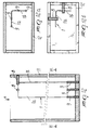
- figures 6 bis and 7 illustrate dowels or pins made of metal, graphite, refractory or ceramic materials, or other adapted material, that can be used to position the insert of figure 6, constituted by a solid cylindrical bar, inside the mold.
- the narrower end of the pin of figure 6 bis is inserted in the wall of the mold, whereas one end of the cylindrical bar-shaped insert of figure 6 is arranged in the seat of the protruding part having a larger diameter.
- the support of figure 7 is substantially constituted by a plate 7 made of metal or other material which is provided with an adapted hole 7a, in which the free end of the cylindrical bar-shaped insert is inserted; the part 7b shown in dashed lines is instead inserted snugly in the wall of the mold.
- Figures 8 to 11a illustrate other supports having a cylindrical or frustum-like shape and provided with laterally formed notches 8b and 10b or with recesses 9b and 11b that are formed at their ends. Said recesses or notches are meant to snugly accommodate the edge of the wings of the various laminar inserts so as to position them stably.
- the insert arranged therein is of the type of the one designated by the reference numeral 1 in figure 1, that is to say, a lamina with an L-shaped profile and with wings 1a and 1b vertically arranged.
- the lower edge of the wing 1a is accommodated in the recess 9b of two vertical cylindrical supports 9 (figure 9), in which the ends that lie opposite to the one provided with the recess are inserted snugly in the back wall of the mold 12; the wing 1b is likewise arranged on two identical supports 9 which are also snugly inserted in the back wall of the mold, as shown by the sectional view of figure 12a.
- Said wings la and 1b are furthermore retained at the top of the mold by means of two cylindrical elements 8 that are horizontally inserted snugly in the contiguous walls of the mold (figure 12b).
- the arrangement of the wings of the insert 1 is such as to allow said insert to remain fully contained inside the mold and thus also inside the finished refractory block, and is also such as to keep its wings stably parallel and close to the inside surfaces of the mold walls.
- the method for casting the molten refractory material inside the mold to achieve the composite structure according to the invention therefore entails the following operating steps:
- the block produced according to the described method can be used for example for each one of the positions numbered 1 to 9 of figure 13.
- Said figure 13 illustrates one of the possible embodiments of the region of the glass furnace technically termed "throat”.
- Intense corrosion of the electro-cast refractory material occurs in this region and mostly affects the blocks in positions 1, 2, and 3, and particularly the block in position 1, which is the most critical element, also from the point of view of its structural function in the throat of figure 13.
- the throat is an essential element of the structure of the furnace, and its wear in practice determines the duty life of said furnace, sometimes entailing an early shutdown. Corrosion of the blocks that constitute the throat occurs according to the typical profile shown in figure 14, where F designates the direction of the flow of molten glass, B designates the profile of the initial block, and t 1 and t 2 designate the progressive corrosion profiles in the times t 1 and t 2 , where t 2 is subsequent to t 1 .
- the insert I shown in dashed lines inside the block in position 1, by interposing itself between the molten glass bath and the refractory material, acts as a protective barrier for the refractory body, preventing said body from making contact with the molten glass, thus avoiding its corrosion and/or erosion and in practice increasing the working life of the block.
Landscapes
- Engineering & Computer Science (AREA)
- Chemical & Material Sciences (AREA)
- Mechanical Engineering (AREA)
- General Engineering & Computer Science (AREA)
- Ceramic Engineering (AREA)
- Organic Chemistry (AREA)
- Manufacturing & Machinery (AREA)
- Materials Engineering (AREA)
- Inorganic Chemistry (AREA)
- Structural Engineering (AREA)
- Ceramic Products (AREA)
- Casting Support Devices, Ladles, And Melt Control Thereby (AREA)
- Furnace Housings, Linings, Walls, And Ceilings (AREA)
- Vertical, Hearth, Or Arc Furnaces (AREA)
- Laminated Bodies (AREA)
- Compositions Of Oxide Ceramics (AREA)
- Glass Compositions (AREA)
Claims (6)
- Structure réfractaire composite et monolithique, pour réaliser des fours de fabrication de verre, comportant un constituant en forme de bloc réalisé en matériau réfractaire électro-moulé à base d'oxydes d'aluminium, de zirconium, de silicium, ayant une forme périphérique et des dimensions qui sont adaptées à son utilisation, à l'intérieur duquel au moins un élément de protection est inséré de manière monolithique, ledit élément de protection étant très résistant à l'attaque de bains de verre fondu et étant sélectionné parmi les métaux, des métaux nobles, des métaux réfractaires, des matériaux réfractaires, des céramiques, telles que des carbures, nitrures, borures ou des matériaux à base de graphite, des alliages et/ou des composés et/ou des composites de ceux-ci, ledit élément de protection étant agencé sensiblement sous la forme d'une plaque mise en forme et dimensionnée pour définir un profil qui est similaire à une partie du profil périphérique du bloc réfractaire qui est adapté pour être exposé à un bain de verre fondu, ledit élément de protection étant entièrement enrobé à l'intérieur du bloc et ayant des ailes définissant des surfaces plates situées à proximité des surfaces extérieures du bloc et sensiblement parallèles à celles-ci qui sont adaptées pour être exposées à l'attaque du bain de verre fondu, de manière à constituer une barrière de protection continue vis à vis de ladite attaque de verre fondu pour le reste que du constituant réfractaire situé derrière ladite barrière de protection
- Structure réfractaire selon la revendication 1, caractérisée en ce que ledit élément de protection est agencé sous la forme d'une plaque ou feuille rigide formée de manière à avoir diverses formes géométriques profilées en forme de "C", "I", "L", "O", "S", "U", "V" ; de tubes cylindriques ou coniques ayant un profil de base constitué d'un périmètre ouvert ou fermé ; de compositions et/ou d'assemblages de ceux-ci, de manière à constituer des corps pleins ou analogues à une boíte ouverts ou fermés, lesdites feuilles ou éléments rapportés étant constitués d'au moins un métal, choisi de préférence parmi le molybdène, le tantale, le tungstène, et le platine, des métaux réfractaires, des céramiques, telles que celles à base de graphite, de carbures, de nitrures, de borures, de siliciures, à la fois tels quels et sous forme d'alliages et/ou des composés et/ou des composites de ceux-ci.
- Procédé de production d'une structure réfractaire composite monolithique telle que définie dans les revendications 1 et 2, en utilisant des moules habituels pour produire des blocs constitués d'un matériau réfractaire électro-moulé ou analogue, caractérisé en ce qu'il consiste à :préparer un moule habituel pour la production d'un bloc de matériau réfractaire électro-moulé ayant les dimensions voulues,préparer au moins un élément rapporté de protection qui est très résistant à l'attaque du verre fondu et a des formes et des dimensions qui sont adaptées pour constituer une barrière de protection continue au moins pour les zones du bloc réfractaire qui sont adaptées pour être les plus exposées à ladite attaque,positionner, à l'intérieur dudit moule, des éléments de support et/ou de suspension dudit élément rapporté, qui sont formés et agencés pour maintenir l'élément rapporté stable et entièrement immergé dans le moule et complètement noyé dans le bloc réfractaire après son moulage, et aussi de telle sorte que ses surfaces soient dans une position parallèle par rapport aux surfaces du bloc qui sont exposées à l'attaque et soient situées à proximité de celles-ci, et ensuitemouler avec des minutages clairement déterminés et planifiés, un matériau réfractaire fondu à l'intérieur dudit moule conformément à un procédé et un équipement d'introduction de matériau fondu qui sont capables d'éviter des déplacements de l'élément rapporté par rapport aux parois du moule, et enfinarrêter le moulage lorsque que le moule est rempli et ensuite refroidir le bloc réfractaire qui contient l'élément rapporté selon des cycles successifs, de manière à aboutir à un contact intime, continu, et permanent entre l'élément rapporté, les éléments de support, et la partie réfractaire.
- Procédé selon la revendication 3 caractérisé en ce que ladite étape de moulage, consiste à mouler un matériau réfractaire sélectionné parmi des matériaux qui peuvent être fondus électriquement ou par d'autres procédés et en particulier parmi des matériaux réfractaires dont les constituants principaux sont sélectionnés parmi Al2O3, SiO2, ZrO2, Cr2O3, MgO et des composés ou des composites de ceux-ci.
- Procédé selon les revendications 3 et 4, caractérisé en ce que dans ladite étape de préparation, des éléments rapportés sont préparés qui sont constitués de préférence de matériaux dont les constituants principaux sont Mo, Pt, Ta, W, des métaux réfractaires en général, des matériaux à base de graphite, des céramiques habituelles et non habituelles et aussi des matériaux particuliers tels que des nitrures, des borures, des carbures, des siliciures, à la fois tels quels et sous forme d'alliages ou de composés et/ou de composites de ceux-ci, qui ont subi des traitements ou processus chimiques partiels ou totaux, physiques, mécaniques, adaptés pour modifier partiellement ou totalement leur nature, aspect, dimension, forme, ou état de surface.
- Procédé selon l'une quelconque des revendications 3 à 5, caractérisé en ce que dans ladite étape de préparation et de moulage, afin d'obtenir un contact stable, intime et mutuel entre la partie réfractaire et les éléments rapportés, les matériaux sélectionnés pour la partie réfractaire, pour les éléments rapportés, et pour les éléments de support et/ou de suspension ont un comportement cohérent en dilatation.
Applications Claiming Priority (3)
| Application Number | Priority Date | Filing Date | Title |
|---|---|---|---|
| ITMI941290 | 1994-06-20 | ||
| ITMI941290A IT1270259B (it) | 1994-06-20 | 1994-06-20 | Struttura composita costituita da un manufatto in refrattario elettrofuso incorporante elementi altamente resistenti alla corrosione/erosione da parte dei bagni fusi ed utilizzabile in particolare per la costruzione dei forni per vetro e simili |
| PCT/EP1995/002365 WO1995035267A1 (fr) | 1994-06-20 | 1995-06-19 | Structure composite comprenant un constituant a base d'un materiau refractaire electrofondu et elements hautement resistants a la corrosion ainsi qu'a l'erosion |
Publications (2)
| Publication Number | Publication Date |
|---|---|
| EP0766656A1 EP0766656A1 (fr) | 1997-04-09 |
| EP0766656B1 true EP0766656B1 (fr) | 1998-09-09 |
Family
ID=11369145
Family Applications (1)
| Application Number | Title | Priority Date | Filing Date |
|---|---|---|---|
| EP95924280A Expired - Lifetime EP0766656B1 (fr) | 1994-06-20 | 1995-06-19 | Structure composite comprenant un constituant a base d'un materiau refractaire electrofondu et elements hautement resistants a la corrosion ainsi qu'a l'erosion |
Country Status (14)
| Country | Link |
|---|---|
| US (1) | US5958814A (fr) |
| EP (1) | EP0766656B1 (fr) |
| JP (1) | JP4002994B2 (fr) |
| CN (1) | CN1078190C (fr) |
| AU (1) | AU692891B2 (fr) |
| BR (1) | BR9508076A (fr) |
| CA (1) | CA2193376A1 (fr) |
| CZ (1) | CZ292248B6 (fr) |
| DE (1) | DE69504671T2 (fr) |
| ES (1) | ES2122648T3 (fr) |
| HU (1) | HU220404B (fr) |
| IT (1) | IT1270259B (fr) |
| SK (1) | SK282596B6 (fr) |
| WO (1) | WO1995035267A1 (fr) |
Families Citing this family (7)
| Publication number | Priority date | Publication date | Assignee | Title |
|---|---|---|---|---|
| KR100773144B1 (ko) * | 2001-10-30 | 2007-11-05 | 삼성코닝 주식회사 | 유리용해로용 스로트 |
| DE10329277B4 (de) * | 2003-06-30 | 2005-11-17 | Schott Ag | Keramik-Molybdän-Verbundmaterialien für den Glaskontakt, Verfahren zur Herstellung und Verwendung |
| JP4504823B2 (ja) * | 2005-01-11 | 2010-07-14 | Hoya株式会社 | ガラスの製造方法及びガラス製造装置、並びにこれらに用いる保護部材 |
| US20090188347A1 (en) * | 2007-03-07 | 2009-07-30 | General Electric Company | Treated refractory material and methods of making |
| EP2225492B1 (fr) * | 2007-12-22 | 2016-01-13 | Jünger + Gräter GmbH Feuerfestbau | Garnissage de paroi de fours industriels |
| JP2021054665A (ja) * | 2019-09-27 | 2021-04-08 | 日本電気硝子株式会社 | ガラス物品の製造装置とその製造方法 |
| CN111848189B (zh) * | 2020-07-24 | 2021-03-30 | 湖南省娄底市宏冶炉料有限责任公司 | 新型耐冲刷耐热震式冲击砖及制备方法和稳流器 |
Family Cites Families (13)
| Publication number | Priority date | Publication date | Assignee | Title |
|---|---|---|---|---|
| BE624097A (fr) * | ||||
| US3239972A (en) * | 1960-09-21 | 1966-03-15 | Detrick M H Co | Means for mounting metallic members in brick moulds |
| US3390505A (en) * | 1966-11-28 | 1968-07-02 | Corning Glass Works | Refractory housing |
| DE1944415B2 (de) * | 1969-09-02 | 1972-01-27 | Didier Werke AG, 6200 Wiesbaden | Gebrannter feuerfester formkoerper mit metallischer einlage |
| US4294795A (en) * | 1978-06-12 | 1981-10-13 | Kureha Kagaku Kogyo Kabushiki Kaisha | Stabilized electrocast zirconia refractories |
| FR2433164A1 (fr) * | 1978-08-08 | 1980-03-07 | Produits Refractaires | Blocs a base d'oxydes refractaires electrofondus armes d'un element en un materiau d'une conductivite thermique elevee |
| US4366571A (en) * | 1981-03-16 | 1982-12-28 | Corning Glass Works | Electric furnace construction |
| US5028572A (en) * | 1986-02-04 | 1991-07-02 | The Carborundum Company | Near net shape fused cast refractories and process for their manufacture by rapid melting/controlled rapid cooling |
| FR2627483A1 (fr) * | 1988-02-19 | 1989-08-25 | Produits Refractaires | Pieces ceramiques minces obtenues par fusion et moulage d'une composition du systeme al2o-zro2-sio2-k2o ayant de bonnes proprietes de resistance mecanique et de resistance a l'abrasion |
| FR2647437B1 (fr) * | 1989-05-26 | 1991-10-04 | Savoie Refractaires | Nouvelles compositions refractaires contenant de la zircone monoclinique et articles formes a partir de ces compositions presentant une resistance mecanique a chaud et une resistance aux chocs thermiques ameliorees |
| JP2628403B2 (ja) * | 1990-09-13 | 1997-07-09 | 東芝モノフラックス株式会社 | 蓄熱室用耐火物セグメント |
| FR2668478B1 (fr) * | 1990-10-24 | 1993-06-25 | Savoie Refractaires | Nouveau materiaux refractaires a matrice de sialon et procede de preparation. |
| JP3667403B2 (ja) * | 1995-10-05 | 2005-07-06 | サンゴバン・ティーエム株式会社 | βアルミナ質電鋳耐火物 |
-
1994
- 1994-06-20 IT ITMI941290A patent/IT1270259B/it active IP Right Grant
-
1995
- 1995-06-19 DE DE69504671T patent/DE69504671T2/de not_active Expired - Lifetime
- 1995-06-19 CA CA002193376A patent/CA2193376A1/fr not_active Abandoned
- 1995-06-19 SK SK1644-96A patent/SK282596B6/sk unknown
- 1995-06-19 BR BR9508076A patent/BR9508076A/pt not_active IP Right Cessation
- 1995-06-19 JP JP50166496A patent/JP4002994B2/ja not_active Expired - Fee Related
- 1995-06-19 HU HU9603546A patent/HU220404B/hu not_active IP Right Cessation
- 1995-06-19 WO PCT/EP1995/002365 patent/WO1995035267A1/fr not_active Ceased
- 1995-06-19 ES ES95924280T patent/ES2122648T3/es not_active Expired - Lifetime
- 1995-06-19 CZ CZ19963581A patent/CZ292248B6/cs not_active IP Right Cessation
- 1995-06-19 EP EP95924280A patent/EP0766656B1/fr not_active Expired - Lifetime
- 1995-06-19 AU AU28854/95A patent/AU692891B2/en not_active Ceased
- 1995-06-19 CN CN95193603A patent/CN1078190C/zh not_active Expired - Fee Related
- 1995-06-19 US US08/750,585 patent/US5958814A/en not_active Expired - Lifetime
Also Published As
| Publication number | Publication date |
|---|---|
| DE69504671D1 (de) | 1998-10-15 |
| CZ358196A3 (en) | 1997-04-16 |
| DE69504671T2 (de) | 1999-04-08 |
| ITMI941290A0 (it) | 1994-06-20 |
| US5958814A (en) | 1999-09-28 |
| HU9603546D0 (en) | 1997-02-28 |
| JPH10501513A (ja) | 1998-02-10 |
| SK164496A3 (en) | 1997-06-04 |
| CN1150793A (zh) | 1997-05-28 |
| IT1270259B (it) | 1997-04-29 |
| CN1078190C (zh) | 2002-01-23 |
| CA2193376A1 (fr) | 1995-12-28 |
| SK282596B6 (sk) | 2002-10-08 |
| HUT77824A (hu) | 1998-08-28 |
| ITMI941290A1 (it) | 1995-12-20 |
| AU2885495A (en) | 1996-01-15 |
| AU692891B2 (en) | 1998-06-18 |
| CZ292248B6 (cs) | 2003-08-13 |
| HU220404B (hu) | 2002-01-28 |
| EP0766656A1 (fr) | 1997-04-09 |
| BR9508076A (pt) | 1998-07-14 |
| JP4002994B2 (ja) | 2007-11-07 |
| ES2122648T3 (es) | 1998-12-16 |
| WO1995035267A1 (fr) | 1995-12-28 |
Similar Documents
| Publication | Publication Date | Title |
|---|---|---|
| EP1452251B1 (fr) | Moule pour la coulée des éléments par solidification dirigée | |
| US4549599A (en) | Preventing mold and casting cracking in high rate directional solidification processes | |
| US5958814A (en) | Composite structure comprising a component of electro-cast refractory and elements highly resistant to corrosion and erosion | |
| EP0635323A1 (fr) | Tuyère pour moulage continu | |
| JP4406753B2 (ja) | 冷却素子製造用鋳型およびその鋳型を用いて製造される冷却素子 | |
| US3336973A (en) | Continuous casting mold | |
| JP2003528285A (ja) | 冷却エレメント製造方法および冷却エレメント | |
| TW201109104A (en) | Casting mold | |
| JPH06503296A (ja) | 囲いブロックを有するガラス融解タンク炉用の融解タンク及びその運転方法 | |
| EP0355940A2 (fr) | Lingotière de coulée continue avec insert remplaçable | |
| JP3105166B2 (ja) | スキッドボタン装置 | |
| RU97100795A (ru) | Композиционная конструкция, содержащая электроплавленый литой огнеупорный компонент и элементы, обладающие высокой стойкостью к коррозии и эрозии | |
| JP2001518394A (ja) | 特に包晶系の鋼を連続鋳造するための連続鋳造鋳型用の管状鋳型 | |
| JPS63224839A (ja) | 圧延用鋼系ロ−ルの鋳造鋳型 | |
| JPS6154506B2 (fr) | ||
| JP5061200B2 (ja) | コーティングを備えた鋳型 | |
| JPS62134139A (ja) | 2層押湯枠 | |
| JP3361044B2 (ja) | スライドゲート用下ノズル | |
| IT202100026120A1 (it) | Lingottiera per la fusione di metallo prezioso e non prezioso, particolarmente per leghe in platino e/o palladio, in un forno a spinta a nastro o a tunnel | |
| JP3362692B2 (ja) | 鋼の連続鋳造方法および鋳型 | |
| JP3895258B2 (ja) | 鋳造用金型およびその製造方法 | |
| JPH06142883A (ja) | アルミニウムダイカスト機の溶湯供給装置 | |
| JPH08254394A (ja) | アーク溶解式歯科鋳造用るつぼ | |
| JP2010515583A5 (ja) | コーティングを備えた鋳型 | |
| KR20000042197A (ko) | 빌렛 연속주조용 내화물 몰드 |
Legal Events
| Date | Code | Title | Description |
|---|---|---|---|
| PUAI | Public reference made under article 153(3) epc to a published international application that has entered the european phase |
Free format text: ORIGINAL CODE: 0009012 |
|
| 17P | Request for examination filed |
Effective date: 19961217 |
|
| AK | Designated contracting states |
Kind code of ref document: A1 Designated state(s): BE DE ES FR GB NL |
|
| GRAG | Despatch of communication of intention to grant |
Free format text: ORIGINAL CODE: EPIDOS AGRA |
|
| 17Q | First examination report despatched |
Effective date: 19970901 |
|
| GRAG | Despatch of communication of intention to grant |
Free format text: ORIGINAL CODE: EPIDOS AGRA |
|
| GRAG | Despatch of communication of intention to grant |
Free format text: ORIGINAL CODE: EPIDOS AGRA |
|
| GRAH | Despatch of communication of intention to grant a patent |
Free format text: ORIGINAL CODE: EPIDOS IGRA |
|
| GRAH | Despatch of communication of intention to grant a patent |
Free format text: ORIGINAL CODE: EPIDOS IGRA |
|
| GRAA | (expected) grant |
Free format text: ORIGINAL CODE: 0009210 |
|
| AK | Designated contracting states |
Kind code of ref document: B1 Designated state(s): BE DE ES FR GB NL |
|
| REF | Corresponds to: |
Ref document number: 69504671 Country of ref document: DE Date of ref document: 19981015 |
|
| REG | Reference to a national code |
Ref country code: ES Ref legal event code: FG2A Ref document number: 2122648 Country of ref document: ES Kind code of ref document: T3 |
|
| ET | Fr: translation filed | ||
| PLBE | No opposition filed within time limit |
Free format text: ORIGINAL CODE: 0009261 |
|
| STAA | Information on the status of an ep patent application or granted ep patent |
Free format text: STATUS: NO OPPOSITION FILED WITHIN TIME LIMIT |
|
| 26N | No opposition filed | ||
| REG | Reference to a national code |
Ref country code: GB Ref legal event code: IF02 |
|
| PGFP | Annual fee paid to national office [announced via postgrant information from national office to epo] |
Ref country code: ES Payment date: 20060612 Year of fee payment: 12 |
|
| PGFP | Annual fee paid to national office [announced via postgrant information from national office to epo] |
Ref country code: GB Payment date: 20060619 Year of fee payment: 12 |
|
| PGFP | Annual fee paid to national office [announced via postgrant information from national office to epo] |
Ref country code: NL Payment date: 20060626 Year of fee payment: 12 |
|
| GBPC | Gb: european patent ceased through non-payment of renewal fee |
Effective date: 20070619 |
|
| NLV4 | Nl: lapsed or anulled due to non-payment of the annual fee |
Effective date: 20080101 |
|
| REG | Reference to a national code |
Ref country code: FR Ref legal event code: TP |
|
| PG25 | Lapsed in a contracting state [announced via postgrant information from national office to epo] |
Ref country code: NL Free format text: LAPSE BECAUSE OF NON-PAYMENT OF DUE FEES Effective date: 20080101 |
|
| PG25 | Lapsed in a contracting state [announced via postgrant information from national office to epo] |
Ref country code: GB Free format text: LAPSE BECAUSE OF NON-PAYMENT OF DUE FEES Effective date: 20070619 |
|
| REG | Reference to a national code |
Ref country code: ES Ref legal event code: FD2A Effective date: 20070620 |
|
| PG25 | Lapsed in a contracting state [announced via postgrant information from national office to epo] |
Ref country code: ES Free format text: LAPSE BECAUSE OF NON-PAYMENT OF DUE FEES Effective date: 20070620 |
|
| PGFP | Annual fee paid to national office [announced via postgrant information from national office to epo] |
Ref country code: DE Payment date: 20130628 Year of fee payment: 19 |
|
| PGFP | Annual fee paid to national office [announced via postgrant information from national office to epo] |
Ref country code: FR Payment date: 20130703 Year of fee payment: 19 |
|
| PGFP | Annual fee paid to national office [announced via postgrant information from national office to epo] |
Ref country code: BE Payment date: 20130619 Year of fee payment: 19 |
|
| REG | Reference to a national code |
Ref country code: DE Ref legal event code: R119 Ref document number: 69504671 Country of ref document: DE |
|
| REG | Reference to a national code |
Ref country code: FR Ref legal event code: ST Effective date: 20150227 |
|
| REG | Reference to a national code |
Ref country code: DE Ref legal event code: R119 Ref document number: 69504671 Country of ref document: DE Effective date: 20150101 |
|
| PG25 | Lapsed in a contracting state [announced via postgrant information from national office to epo] |
Ref country code: DE Free format text: LAPSE BECAUSE OF NON-PAYMENT OF DUE FEES Effective date: 20150101 |
|
| PG25 | Lapsed in a contracting state [announced via postgrant information from national office to epo] |
Ref country code: FR Free format text: LAPSE BECAUSE OF NON-PAYMENT OF DUE FEES Effective date: 20140630 |
|
| PG25 | Lapsed in a contracting state [announced via postgrant information from national office to epo] |
Ref country code: BE Free format text: LAPSE BECAUSE OF NON-PAYMENT OF DUE FEES Effective date: 20140630 |