EP0768409A2 - Verfahren zum Kühlen eines Greiferantriebes und Webmaschine mit kühlbarem Greiferantrieb - Google Patents
Verfahren zum Kühlen eines Greiferantriebes und Webmaschine mit kühlbarem Greiferantrieb Download PDFInfo
- Publication number
- EP0768409A2 EP0768409A2 EP96113974A EP96113974A EP0768409A2 EP 0768409 A2 EP0768409 A2 EP 0768409A2 EP 96113974 A EP96113974 A EP 96113974A EP 96113974 A EP96113974 A EP 96113974A EP 0768409 A2 EP0768409 A2 EP 0768409A2
- Authority
- EP
- European Patent Office
- Prior art keywords
- drive
- housing
- air
- gripper drive
- area
- Prior art date
- Legal status (The legal status is an assumption and is not a legal conclusion. Google has not performed a legal analysis and makes no representation as to the accuracy of the status listed.)
- Granted
Links
- 238000000034 method Methods 0.000 title claims description 9
- 238000001816 cooling Methods 0.000 title claims description 5
- 238000009941 weaving Methods 0.000 claims abstract description 8
- 239000003636 conditioned culture medium Substances 0.000 claims abstract description 5
- 239000002609 medium Substances 0.000 claims description 7
- 239000000835 fiber Substances 0.000 abstract description 11
- 238000003780 insertion Methods 0.000 abstract description 4
- 230000037431 insertion Effects 0.000 abstract description 4
- 230000000694 effects Effects 0.000 abstract 1
- 230000002045 lasting effect Effects 0.000 abstract 1
- 239000004744 fabric Substances 0.000 description 2
- 210000000056 organ Anatomy 0.000 description 2
- 229920002430 Fibre-reinforced plastic Polymers 0.000 description 1
- 238000005299 abrasion Methods 0.000 description 1
- 238000009825 accumulation Methods 0.000 description 1
- 230000001143 conditioned effect Effects 0.000 description 1
- 239000011151 fibre-reinforced plastic Substances 0.000 description 1
- 230000001771 impaired effect Effects 0.000 description 1
- 238000004519 manufacturing process Methods 0.000 description 1
- 239000000463 material Substances 0.000 description 1
- 239000002245 particle Substances 0.000 description 1
- 239000004033 plastic Substances 0.000 description 1
- 229920003023 plastic Polymers 0.000 description 1
- 230000002459 sustained effect Effects 0.000 description 1
Images
Classifications
-
- D—TEXTILES; PAPER
- D03—WEAVING
- D03D—WOVEN FABRICS; METHODS OF WEAVING; LOOMS
- D03D47/00—Looms in which bulk supply of weft does not pass through shed, e.g. shuttleless looms, gripper shuttle looms, dummy shuttle looms
- D03D47/27—Drive or guide mechanisms for weft inserting
- D03D47/271—Rapiers
- D03D47/273—Rapier rods
-
- D—TEXTILES; PAPER
- D03—WEAVING
- D03D—WOVEN FABRICS; METHODS OF WEAVING; LOOMS
- D03D47/00—Looms in which bulk supply of weft does not pass through shed, e.g. shuttleless looms, gripper shuttle looms, dummy shuttle looms
- D03D47/27—Drive or guide mechanisms for weft inserting
- D03D47/271—Rapiers
-
- D—TEXTILES; PAPER
- D03—WEAVING
- D03J—AUXILIARY WEAVING APPARATUS; WEAVERS' TOOLS; SHUTTLES
- D03J1/00—Auxiliary apparatus combined with or associated with looms
- D03J1/002—Climatic conditioning or removing lint or dust
-
- D—TEXTILES; PAPER
- D03—WEAVING
- D03J—AUXILIARY WEAVING APPARATUS; WEAVERS' TOOLS; SHUTTLES
- D03J1/00—Auxiliary apparatus combined with or associated with looms
- D03J1/008—Cooling systems
Definitions
- the invention relates to a method for cooling a rapier drive and a weaving machine with a coolable rapier drive.
- Various types of training are known for the grippers and their support members, as well as for their drive.
- a known type uses long, rigid rods, at one end of which the gripper is arranged for gripping and transferring the weft thread.
- the known rod-like support members are relatively stiff and low in mass.
- Such support members are made of fiber-reinforced plastic and have a U-shaped profile cross-section with an integrated rack-like toothing, with which at least one drive pinion is meshingly engaged with an alternating direction of rotation.
- Other support members consist of flexible bands, at one end of which a gripper is seated, while the other end is connected to a drive wheel.
- the belts must have a certain stiffness and at the same time be flexible enough to be wound up and unwound on the drive advice, which is driven with an alternating direction of rotation.
- All carrier elements connected to drive wheels and corresponding guides are subject to certain limits with regard to the weft insertion rate, in particular because of the frictional heat generated in the drive and guide area of the carrier elements.
- the friction leads to rapid wear of the elements involved in the drive and in guiding the support members.
- the operating time of the drive and management elements is sustained the fiber flight arising in the weaving process and entering the area of the rapier drive and the area of the guide members is impaired.
- the invention is therefore based on the object, firstly to dissipate the frictional heat generated in the area of the drive and the guide of the carrier members and to achieve a targeted cooling of these members, and secondly to keep the fiber fly arising during the weaving process largely away from the drive, carrier and guide members.
- the gripper drive which is formed from a rack-like support member and from at least one pinion driven with an alternating direction of rotation, and the drive being surrounded by a housing shielding the fiber flight, is supplied with or removed from an air-conditioned medium under pressure.
- the housing is connected to a pressure line, via which the conditioned medium is supplied or withdrawn from the housing under pressure. If the medium is supplied, it flows around the area of the gripper drive and reaches the guide rollers, which are also cooled, via slot-like openings which exist between the housing wall surrounding the carrier element on the one hand and the guide rollers or the bearing plate and the housing wall on the other hand.
- the pressure line is connected to a vacuum source, which creates a negative pressure in the housing.
- air is drawn into the housing, for example from the atmosphere, via the slot-like openings.
- Such a solution can be used, for example, in the production of technical fabrics, from monofilaments in warp and weft.
- the compressed air leads to a significant drop in temperature Gripper drive and on the guides of the carrier member.
- the air flow exiting the slot-like openings with overpressure ensures that fiber fly cannot settle in the area of the gripper drive and, on the other hand, during vacuum operation, the fiber fly is removed from the suction air flow.
- the solution according to the invention increases the wear resistance of the organs involved in the weft insertion, in particular the carrier organs, the drive pinion and the guide rollers. Due to the cooling of the drive, support and guiding elements from the air-conditioned medium, a performance increase of the weaving machine of about 10% is achieved and finally the medium emerging from the outflow openings at a certain speed ensures that an accumulation of fiber fly on the gripper drive elements and is avoided in their environment and thus it is excluded that fiber fly mixed with oil or fat-containing abrasion particles can get from the gripper drive into the fabric to be produced.
- the invention is explained below using an exemplary embodiment.
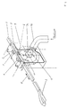
- the drawing shows the gripper drive and the surrounding housing in perspective.
- the exemplary embodiment is based on the carrier element 1 for the weft thread, a gripper bar which carries at its front end a gripper 2 which has devices for gripping, holding and releasing the weft thread.
- the design of the gripper 2 is not important for the invention. It is therefore not discussed in any more detail.
- the carrier member 1 here consists of a U-shaped profile cross section with an integrated Rack or integrated rack-like toothing, with which at least one drive pinion 7 is meshingly engaged.
- the drive pinion 7 is connected in a rotationally fixed manner to a drive shaft 7a, which drives the drive pinion 7 with an alternating direction of rotation according to double arrow 11.
- the direction of rotation of the drive pinion 7 and the direction of movement of the carrier member 1 with the gripper 2 is indicated by a double arrow 11, 12.
- the storage and guidance of the carrier member 1 takes place here in the example by rollers 4, 5, 6.
- the rollers 4, 5 serve to guide the carrier member 1 vertically.
- the lateral guidance of the carrier member 1 is carried out by at least one guide roller 6.
Landscapes
- Engineering & Computer Science (AREA)
- Textile Engineering (AREA)
- Looms (AREA)
Abstract
Im Eingriffsbereich von Trägerorgan 1 und Antriebsritzel 7 entsteht während des Betriebs Friktionswärme. Die Wärme wirkt sich sowohl negativ auf die Lebensdauer des Greiferantriebs als auch negativ auf die Schußeintragsleistung aus.
Außerdem beeinträchtigt Faserflug die Funktionsfähigkeit des Greiferantriebs nachhaltig.
Aufgabe der Erfindung ist es, die im Greiferantriebsbereich entstehende Friktionswärme abzuführen und Faserflug von den Antriebs-, Träger- und Führungsorganen weitgehend fernzuhalten.
Das erfolgt dadurch, daß der Bereich des Greiferantriebs von einem Gehäuse unter Bildung von Strömungsöffnungen 9 umschlossen ist, in das unter Druck ein klimatisiertes Medium geleitet wird, welches den Antriebsbereich umspült und über die Strömungsöffnungen 9 entweicht.
Vorteilhaft wirkt sich aus, daß mit der erfindungsgemäßen Maßnahme die Temperatur im Greiferantriebsbereich deutlich gesenkt und die Schußeintragsleistung um etwa 10 % gesteigert werden kann.
Description
- Die Erfindung betrifft ein Verfahren zum Kühlen eines Greiferantriebes und eine Webmaschine mit kühlbarem Greiferantrieb.
Für die Greifer und ihre Trägerorgane, sowie für ihren Antrieb sind verschiedenartige Ausbildungen bekannt. Eine bekannte Art verwendet lange, steife Stangen, an deren einem Ende der Greifer zur Erfassung und Übergabe des Schußfadens angeordnet ist.
Die bekannten stangenartigen Trägerorgane sind verhältnismäßig steif und zugleich massearm ausgebildet. Derartige Trägerorgane bestehen aus faserverstärktem Kunststoff und besitzen einen U-förmigen Profilquerschnitt mit einer integrierten zahnstangenartigen Verzahnung, mit der wenigstens ein Antriebsritzel mit wechselndem Drehsinn kämmend in Eingriff steht. - Andere Trägerorgane bestehen aus flexiblen Bändern, an deren einem Ende ein Greifer sitzt, während das andere Ende mit einem Antriebsrad in Verbindung steht.
Die Bänder müssen eine gewisse Steifigkeit aufweisen und zugleich flexibel genug sein, um auf das Antriebsrat, das mit wechselndem Drehsinn angetrieben wird, auf- und abgewickelt zu werden. - Allen mit Antriebsrädern und entsprechenden Führungen in Verbindung stehenden Trägerorganen sind im Hinblick auf die Schußeintragsleistung, insbesondere wegen der im Antriebs- und Führungsbereich der Trägerorgane entstehenden Friktionswärme, gewisse Grenzen gesetzt.
Insbesondere dann, wenn die Materialpaarung zwischen Trägerorgan und Antriebsritzel auf einer Kunststoffbasis beruht, führt die Friktion zu einem schnellen Verschleiß der am Antrieb und an der Führung der Trägerorgane beteiligten Elemente.
Ferner wird die Betriebsdauer der Antriebs- und Führungsorgane nachhaltig durch den im Webprozeß entstehenden und in den Bereich des Greiferantriebs sowie in den Bereich der Führungsorgane gelangenden Faserflug beeinträchtigt. - Der Erfindung liegt daher die Aufgabe zugrunde, erstens die im Bereich des Antriebs und der Führung der Trägerorgane entstehende Friktionswärme abzuführen und eine gezielte Kühlung dieser Organe zu erreichen und zweitens den während des Webprozesses entstehenden Faserflug von den Antriebs-, Träger- und Führungsorgane weitgehend fernzuhalten.
- Erfindungsgemäß wird die Aufgabe durch die kennzeichnenden Merkmale der Patentansprüche gelöst.
- Danach ist erfindungswesentlich, daß dem Greiferantrieb, welcher aus einem zahnstangenartig ausgebildeten Trägerorgan und aus wenigstens einem mit wechselndem Drehsinn angetriebenen Ritzel gebildet ist und wobei der Antrieb von einem den Faserflug abschirmenden Gehäuse umgeben ist, unter Druck ein klimatisiertes Medium zugeführt oder entzogen wird.
Dabei ist das Gehäuse an eine Druckleitung angeschlossen, über die das klimatisierte Medium unter Druck dem Gehäuse zugeführt oder entzogen wird.
Wird das Medium zugeführt, umspült es den Bereich des Greiferantriebes und gelangt über schlitzartige Öffnungen, die zwischen der das Trägerorgan umgebenden Gehäusewandung einerseits und den Führungsrollen bzw. der Lagerplatte und der Gehäusewandung andererseits bestehen, zu den Führungsrollen, die ebenfalls gekühlt werden.
Wird das Medium dem Gehäuse entzogen, dann ist die Druckleitung an eine Vakuumquelle angeschlossen, die im Gehäuse einen Unterdruck entstehen läßt.
Hierbei wird über die schlitzartigen Öffnungen Luft, z.B. aus der Atmosphäre in das Gehäuse gesogen. Eine solche Lösung kann z.B. Anwendung finden bei der Herstellung von technischen Geweben, aus Monofilen in Kette und Schuß.
In beiden Fällen führt die Druckluft zu einer deutlichen Temperaturabsenkung am Greiferantrieb und an den Führungen des Trägerorgans.
In beiden Fällen besteht auch nicht mehr die Gefahr, daß Faserflug in den Bereich
des Greiferantriebs und der Rollenführungen gelangt.
Zum einen sorgt die mit Überdruck aus den schlitzartigen Öffnungen austretende Luftströmung dafür, daß sich Faserflug nicht im Bereich des Greiferantriebes absetzen kann und zum anderen wird bei Vakuumbetrieb der Faserflug von dem Saugluftstrom abgeführt. - Mit der erfindungsgemäßen Lösung wird eine Erhöhung der Verschleißbeständigkeit der am Schußeintrag beteiligten Organe, insbesondere der Trägerorgane, des Antriebritzels und der Führungsrollen erzielt.
Durch die von dem klimatisierten Medium ausgehende Kühlung der Antriebs-, Träger- und Führungsorgane wird eine Leistungssteigerung der Webmaschine von etwa 10 % erreicht und schließlich sorgt das mit einer bestimmten Geschwindigkeit aus den Ausströmöffnungen tretende Medium dafür, daß eine Ansammlung von Faserflug an den Greiferantriebsorganen und in deren Umgebung vermieden wird und damit ausgeschlossen ist, daß mit öl- oder fetthaltigen Abriebpartikeln versetzter Faserflug aus dem Greiferantrieb in das herzustellende Gewebe gelangt. - Die Erfindung wird nachfolgend anhand eines Ausführungsbeispieles erläutert.
Die Zeichnung zeigt den Greiferantrieb und das umschließende Gehäuse in perspektivischer Darstellung. - Dem Ausführungsbeispiel liegt als Trägerorgan 1 für den Schußfaden eine Greiferstange zugrunde, die an ihrem vorderen Ende einen Greifer 2 trägt, der Einrichtungen zum Erfassen, Festhalten und Freigeben des Schußfadens besitzt.
Die Ausbildung des Greifers 2 ist für die Erfindung nicht von Bedeutung. Es wird daher darauf nicht näher eingegangen.
Das Trägerorgan 1 besteht hier aus einem U-förmigen Profilquerschnitt mit integrierter Zahnstange bzw. integrierter zahnstangenartiger Verzahnung, mit der wenigstens ein Antriebsritzel 7 kämmend in Eingriff steht.
Das Antriebsritzel 7 ist mit einer Antriebswelle 7a drehfest verbunden, welche das Antriebsritzel 7 mit wechselndem Drehsinn gemäß Doppelpfeil 11 antreibt.
Die Drehrichtung des Antriebsritzels 7 und die Bewegungsrichtung des Trägerorgans 1 mit dem Greifer 2 ist durch jeweils einen Doppelpfeil 11,12 angedeutet.
Die Lagerung und Führung des Trägerorgans 1 erfolgt hier im Beispiel durch Rollen 4, 5, 6.
Eine Lagerplatte 3, die in nicht näher beschriebener Weise maschinenfest angeordnet ist, trägt um horizontal liegende Achsen drehend gelagerte Führungsrollen 4,5. Die Rollen 4,5 dienen der Vertikalführung des Trägerorgans 1.
Die seitliche Führung des Trägerorgans 1 erfolgt durch wenigstens eine Führungsrolle 6. - Das Antriebsritzel 7 und der Bereich, in welchem das Ritzel 7 mit dem Trägerorgan 1 in Zahneingriff steht, ist von einem Gehäuse 8 umschlossen.
Zwischen dem Trägerorgan 1 und der das Trägerorgan 1 umschließenden Schnittfläche der Wand 8a des nach oben hin offenen Gehäuses 8 und zwischen der Unterseite der die Führungsrollen 4,5,6 tragenden Lagerplatte 3 und der Schnittfläche der Wand 8a sind schlitzartige Öffnungen 9 vorhanden, welche einen Durchgang für Luftströmungen bilden.
Zum Beispiel auf der Frontseite ist das Gehäuse 8 an eine Druckleitung 10 anschließbar, über welche klimatisierte Luft unter Druck in das Gehäuseinnere geleitet wird. Der Luftstrom umspült den Antriebsbereich des Trägerorgans 1 und kühlt dabei das Trägerorgan 1 und das Antriebsritzel 7.
Die eingeblasene Luft verläßt das Gehäuse 8 über die Öffnungen 9 und verhindert
dadurch, daß Faserflug in den Greiferantrieb gelangt.
Wird das Gehäuse über die Druckleitung 10 an eine Unterdruckwelle angeschlossen, so erfolgt die Kühlung des Greiferantriebs durch die über die Öffnungen 9 von außen in das Gehäuseinnere gesogene und über die Druckleitung 10 abgeführte Saugluft. - 01
- Trägerorgan
- 02
- Greifer
- 03
- Lagerplatte
- 04
- Führungsrolle
- 05
- Führungsrolle
- 06
- Führungsrolle
- 07
- Antriebsritzel
- 07a
- Antriebswelle
- 08
- Gehäuse
- 08a
- Wand
- 09
- Öffnung
- 10
- Druckleitung
- 11
- Doppelpfeil
- 12
- Doppelpfeil
Claims (7)
- Verfahren zum Kühlen eines von einem Gehäuse umgebenen Greiferantriebs einer Webmaschine, dadurch gekennzeichnet, daß dem Gehäuse von außen und unter Druck ein wärmeabführendes Medium zuführbar oder entziehbar ist, welches Medium vorzugsweise den Greiferantrieb umspült.
- Verfahren nach Anspruch 1, dadurch gekennzeichnet, daß das zuführbare Medium Luft ist und wobei das Gehäuse an eine Überdruckquelle angeschlossen ist.
- Verfahren nach Anspruch 1, dadurch gekennzeichnet, daß das entziehbare Medium Luft ist und wobei das Gehäuse an eine Vakuumquelle angeschlossen ist.
- Verfahren nach Anspruch 2, dadurch gekennzeichnet, daß die zuführbare Luft eine hohe Luftfeuchtigkeit besitzt und/oder klimatisiert ist.
- Verfahren nach Anspruch 1, dadurch gekennzeichnet, daß wenigstens die zuführbare Luft gefiltert ist.
- Webmaschine mit kühlbarem Greiferantrieb, wobei der Schußeintrag durch alternierend in ein Webfach vor- und zurückschiebbare Trägerorgane (1) erfolgt, die einen an deren einem Ende angeordneten Greifer (2) aufweisen, wobei jedes Trägerorgan (1) zahnstangenartig ausgebildet ist und außerhalb des Webfaches durch an einer oberhalb des jeweiligen Trägerorgans (1) liegenden Lagerplatte (3) angeordnete Führungsrollen (4,5,6) gelagert ist und jedes Trägerorgan (1) mit wenigstens einem Antriebsritzel (7) in Eingriff steht, das von einem Gehäuse (8) umgeben ist, dadurch gekennzeichnet, daß das Gehäuse (8) an eine Druckleitung (10) angeschlossen ist, über welche ein klimatisiertes Medium unter Druck
dem Gehäuse (8) zuführ- oder aus dem Gehäuse (8) entziehbar ist und wobei wenigstens zwischen dem von der Wand (8a) des Gehäuses (8) umgebenen Trägerorgan (1) und zwischen der die Führungsrollen (4,5,6) tragenden Lagerplatte (3) eine schlitzartige Öffnung (9) besteht, welche einen Strömungsdurchgang bildet. - Webmaschine nach Anspruch 6, dadurch gekennzeichnet, daß das Gehäuse (8) nach oben hin offen ist und daß zwischen der Stirnfläche (8b) der Gehäusewandung (8a) und der Lagerplatte (3) eine schlitzartige Öffnung (9) besteht.
Applications Claiming Priority (2)
| Application Number | Priority Date | Filing Date | Title |
|---|---|---|---|
| DE19538287 | 1995-10-14 | ||
| DE19538287A DE19538287C1 (de) | 1995-10-14 | 1995-10-14 | Webmaschine mit kühlbarem Greiferantrieb |
Publications (3)
| Publication Number | Publication Date |
|---|---|
| EP0768409A2 true EP0768409A2 (de) | 1997-04-16 |
| EP0768409A3 EP0768409A3 (de) | 1998-04-15 |
| EP0768409B1 EP0768409B1 (de) | 2000-11-02 |
Family
ID=7774855
Family Applications (1)
| Application Number | Title | Priority Date | Filing Date |
|---|---|---|---|
| EP96113974A Expired - Lifetime EP0768409B1 (de) | 1995-10-14 | 1996-08-31 | Verfahren zum Kühlen eines Greiferantriebes und Webmaschine mit kühlbarem Greiferantrieb |
Country Status (4)
| Country | Link |
|---|---|
| US (1) | US5727601A (de) |
| EP (1) | EP0768409B1 (de) |
| JP (1) | JP2986744B2 (de) |
| DE (2) | DE19538287C1 (de) |
Families Citing this family (6)
| Publication number | Priority date | Publication date | Assignee | Title |
|---|---|---|---|---|
| DE19711594A1 (de) * | 1997-03-20 | 1998-09-24 | Dornier Gmbh Lindauer | Vorrichtung zur Führung und Lagerung eines Greifertragorganes in Webmaschinen |
| BE1014950A3 (nl) * | 2001-08-29 | 2004-07-06 | Wiele Michel Van De Nv | Inrichting voor het aandrijven en geleiden van een grijper van een weefmachine. |
| US6820655B2 (en) * | 2002-03-22 | 2004-11-23 | Hans Adolf Beeh | Loom and room conditioning system |
| DE102006016873B3 (de) * | 2006-04-07 | 2007-08-02 | Lindauer Dornier Gmbh | Greiferstangen-Antrieb einer Webmaschine und Webmaschine mit einem Greifersystem |
| BE1022754B1 (nl) * | 2015-02-26 | 2016-08-30 | Picanol Nv | Geleidingsinrichting voor een lans voor een grijperweefmachine |
| BE1027262B1 (nl) * | 2019-05-07 | 2020-12-08 | Vandewiele Nv | Geleidingsinrichting voor een grijperstang en grijperweefmachine omvattende een dergelijke geleidingsinrichting |
Family Cites Families (12)
| Publication number | Priority date | Publication date | Assignee | Title |
|---|---|---|---|---|
| CH514707A (de) * | 1970-10-27 | 1971-10-31 | Fischer Ag Brugg Georg | Vorrichtung zum Absaugen von Faserresten und Staubteilchen an Schussfadeneintragsorganen an Webmaschinen |
| DE2220566A1 (de) * | 1971-06-28 | 1973-01-11 | Falk Corp | Innekuehlsystem fuer untersetzungsgetriebe |
| CH577577A5 (de) * | 1974-12-24 | 1976-07-15 | Rueti Ag Maschf | |
| US4117869A (en) * | 1977-05-20 | 1978-10-03 | Parks-Cramer (Great Britain) Ltd. | Oil mist lubricated textile machine and method |
| CH657640A5 (de) * | 1983-03-23 | 1986-09-15 | Saurer Ag Adolph | Greiferwebmaschine. |
| WO1988007600A1 (fr) * | 1987-04-03 | 1988-10-06 | Textilma Ag | Metier a tisser a pince |
| BE1000506A4 (nl) * | 1987-04-28 | 1989-01-03 | Picanol Nv | Werkwijze voor de koeling van een grijperaandrijving bij weefmachines,en grijperaandrijving om deze werkwijze te verwezenlijken. |
| DE4120568A1 (de) * | 1991-03-08 | 1992-09-10 | Textilma Ag | Greiferwebmaschine |
| JPH0527071U (ja) * | 1991-09-17 | 1993-04-06 | 津田駒工業株式会社 | レピアバンド用バンドガイド |
| BE1005766A3 (nl) * | 1992-04-15 | 1994-01-18 | Picanol Nv | Werkwijze voor het klimatiseren van een weefmachine in een weefzaal en weefmachine om deze werkwijze toe te passen. |
| IT1281187B1 (it) * | 1992-10-23 | 1998-02-17 | Inter Patent Limited | Dispositivo di azionamento dei nastri porta pinza per macchine per tessitura |
| JPH06192948A (ja) * | 1992-12-25 | 1994-07-12 | Nissan Motor Co Ltd | 織機の空調装置 |
-
1995
- 1995-10-14 DE DE19538287A patent/DE19538287C1/de not_active Expired - Fee Related
-
1996
- 1996-08-31 DE DE59606083T patent/DE59606083D1/de not_active Expired - Lifetime
- 1996-08-31 EP EP96113974A patent/EP0768409B1/de not_active Expired - Lifetime
- 1996-09-30 US US08/723,533 patent/US5727601A/en not_active Expired - Fee Related
- 1996-10-14 JP JP8271059A patent/JP2986744B2/ja not_active Expired - Fee Related
Also Published As
| Publication number | Publication date |
|---|---|
| DE19538287C1 (de) | 1997-06-19 |
| DE59606083D1 (de) | 2000-12-07 |
| EP0768409B1 (de) | 2000-11-02 |
| JP2986744B2 (ja) | 1999-12-06 |
| US5727601A (en) | 1998-03-17 |
| JPH09209238A (ja) | 1997-08-12 |
| EP0768409A3 (de) | 1998-04-15 |
Similar Documents
| Publication | Publication Date | Title |
|---|---|---|
| DE3025065C2 (de) | ||
| EP0768409B1 (de) | Verfahren zum Kühlen eines Greiferantriebes und Webmaschine mit kühlbarem Greiferantrieb | |
| DD296118A5 (de) | Verbesserte kettgarnspannvorrichtung fuer einen webstuhl | |
| DE69503022T2 (de) | Schussfadenschmiervorrichtung für Webmaschinen | |
| EP1164213A1 (de) | Vorrichtung zum Bilden einer Drehkante, insbesondere für Webmaschinen | |
| EP0866156B1 (de) | Webmaschine mit einer Vorrichtung zur Führung und Lagerung eines starr ausgebildeten Greifertragorgans | |
| DE60215724T2 (de) | Führungsvorrichtung, Jacquardwebgeschirr und Fachbildungsvorrichtung mit einer solchen Vorrichtung und Verfahren zum Führen der Harnischschnüre einer Jacquardwebmaschine | |
| CH684101A5 (de) | Verfahren und Vorrichtung zur Webmaschinenklimatisierung. | |
| DE9208800U1 (de) | Webmaschine | |
| DE4211786A1 (de) | Vorrichtung zum reinigen von wenigstens einem textilfaden | |
| EP1171658B1 (de) | Einrichtung zur lärmminderung, klimatisierung und unfallverhütung für eine jaquardwebmaschine und eine jaquardwebmaschine mit einer solchen einrichtung | |
| DE102004061550A1 (de) | Schärmaschine, Garnänderungsvorrichtung, und Schärverfahren | |
| DE69810329T2 (de) | Vorrichtung zum schneiden von schussgarn in luftdüsenwebmaschinen | |
| DE3876681T2 (de) | Vorrichtung zur entfernung von abfallmaterial von textilmaschinen. | |
| EP2607531B1 (de) | Vorspinnmaschine | |
| EP0405367A1 (de) | Verfahren zur Aufrechterhaltung der Funktionssicherheit eines Bedienläufers für Spinnereimaschinen | |
| DE2758778B2 (de) | Webmaschine | |
| CH681901A5 (de) | ||
| DE3103020A1 (de) | Pneumatische reinigungsvorrichtung, vorzugsweise fuer jacquardwebmaschinen mit elastischen harnischrueckzugselementen | |
| DE3331071C2 (de) | ||
| DD250963B1 (de) | Pneumatische reinigungsvorrichtung fuer textilmaschinen, insb. fuer wellenfachwebmaschinen | |
| DE3700111A1 (de) | Zusatzgeraet fuer eine halbautomatische kettfaden-einzieheinrichtung fuer webmaschinen | |
| EP1405943B1 (de) | Webmaschine zur Herstellung von Drehergeweben | |
| DE602004012007T2 (de) | Vorrichtung zur Herstellung von einem textilen Stoff | |
| DE1535491C (de) | Greiferstange fur schutzenlose Webmaschinen mit Schußfadeneintrag durch Greifersysteme |
Legal Events
| Date | Code | Title | Description |
|---|---|---|---|
| PUAI | Public reference made under article 153(3) epc to a published international application that has entered the european phase |
Free format text: ORIGINAL CODE: 0009012 |
|
| AK | Designated contracting states |
Kind code of ref document: A2 Designated state(s): BE CH DE FR GB IT LI |
|
| PUAL | Search report despatched |
Free format text: ORIGINAL CODE: 0009013 |
|
| AK | Designated contracting states |
Kind code of ref document: A3 Designated state(s): BE CH DE FR GB IT LI |
|
| 17P | Request for examination filed |
Effective date: 19980831 |
|
| GRAG | Despatch of communication of intention to grant |
Free format text: ORIGINAL CODE: EPIDOS AGRA |
|
| GRAG | Despatch of communication of intention to grant |
Free format text: ORIGINAL CODE: EPIDOS AGRA |
|
| GRAH | Despatch of communication of intention to grant a patent |
Free format text: ORIGINAL CODE: EPIDOS IGRA |
|
| 17Q | First examination report despatched |
Effective date: 20000317 |
|
| GRAH | Despatch of communication of intention to grant a patent |
Free format text: ORIGINAL CODE: EPIDOS IGRA |
|
| GRAA | (expected) grant |
Free format text: ORIGINAL CODE: 0009210 |
|
| AK | Designated contracting states |
Kind code of ref document: B1 Designated state(s): BE CH DE FR GB IT LI |
|
| REG | Reference to a national code |
Ref country code: CH Ref legal event code: EP |
|
| REG | Reference to a national code |
Ref country code: CH Ref legal event code: NV Representative=s name: DIPL.-ING. ETH H. R. WERFFELI PATENTANWALT |
|
| REF | Corresponds to: |
Ref document number: 59606083 Country of ref document: DE Date of ref document: 20001207 |
|
| ET | Fr: translation filed | ||
| ITF | It: translation for a ep patent filed | ||
| GBT | Gb: translation of ep patent filed (gb section 77(6)(a)/1977) |
Effective date: 20010117 |
|
| PLBE | No opposition filed within time limit |
Free format text: ORIGINAL CODE: 0009261 |
|
| STAA | Information on the status of an ep patent application or granted ep patent |
Free format text: STATUS: NO OPPOSITION FILED WITHIN TIME LIMIT |
|
| 26N | No opposition filed | ||
| REG | Reference to a national code |
Ref country code: GB Ref legal event code: IF02 |
|
| PGFP | Annual fee paid to national office [announced via postgrant information from national office to epo] |
Ref country code: FR Payment date: 20050706 Year of fee payment: 10 |
|
| PGFP | Annual fee paid to national office [announced via postgrant information from national office to epo] |
Ref country code: GB Payment date: 20050812 Year of fee payment: 10 |
|
| GBPC | Gb: european patent ceased through non-payment of renewal fee |
Effective date: 20060831 |
|
| REG | Reference to a national code |
Ref country code: FR Ref legal event code: ST Effective date: 20070430 |
|
| PG25 | Lapsed in a contracting state [announced via postgrant information from national office to epo] |
Ref country code: GB Free format text: LAPSE BECAUSE OF NON-PAYMENT OF DUE FEES Effective date: 20060831 |
|
| PG25 | Lapsed in a contracting state [announced via postgrant information from national office to epo] |
Ref country code: FR Free format text: LAPSE BECAUSE OF NON-PAYMENT OF DUE FEES Effective date: 20060831 |
|
| PGFP | Annual fee paid to national office [announced via postgrant information from national office to epo] |
Ref country code: DE Payment date: 20090730 Year of fee payment: 14 |
|
| PGFP | Annual fee paid to national office [announced via postgrant information from national office to epo] |
Ref country code: CH Payment date: 20100825 Year of fee payment: 15 |
|
| PGFP | Annual fee paid to national office [announced via postgrant information from national office to epo] |
Ref country code: IT Payment date: 20100825 Year of fee payment: 15 |
|
| PGFP | Annual fee paid to national office [announced via postgrant information from national office to epo] |
Ref country code: BE Payment date: 20100823 Year of fee payment: 15 |
|
| REG | Reference to a national code |
Ref country code: DE Ref legal event code: R119 Ref document number: 59606083 Country of ref document: DE Effective date: 20110301 |
|
| PG25 | Lapsed in a contracting state [announced via postgrant information from national office to epo] |
Ref country code: DE Free format text: LAPSE BECAUSE OF NON-PAYMENT OF DUE FEES Effective date: 20110301 |
|
| BERE | Be: lapsed |
Owner name: *LINDAUER DORNIER G.M.B.H. Effective date: 20110831 |
|
| REG | Reference to a national code |
Ref country code: CH Ref legal event code: PL |
|
| PG25 | Lapsed in a contracting state [announced via postgrant information from national office to epo] |
Ref country code: CH Free format text: LAPSE BECAUSE OF NON-PAYMENT OF DUE FEES Effective date: 20110831 Ref country code: LI Free format text: LAPSE BECAUSE OF NON-PAYMENT OF DUE FEES Effective date: 20110831 |
|
| PG25 | Lapsed in a contracting state [announced via postgrant information from national office to epo] |
Ref country code: IT Free format text: LAPSE BECAUSE OF NON-PAYMENT OF DUE FEES Effective date: 20110831 Ref country code: BE Free format text: LAPSE BECAUSE OF NON-PAYMENT OF DUE FEES Effective date: 20110831 |