EP0770905A2 - Digitale Korrektur für eine Behandlungsempfindlichkeit - Google Patents
Digitale Korrektur für eine Behandlungsempfindlichkeit Download PDFInfo
- Publication number
- EP0770905A2 EP0770905A2 EP96202826A EP96202826A EP0770905A2 EP 0770905 A2 EP0770905 A2 EP 0770905A2 EP 96202826 A EP96202826 A EP 96202826A EP 96202826 A EP96202826 A EP 96202826A EP 0770905 A2 EP0770905 A2 EP 0770905A2
- Authority
- EP
- European Patent Office
- Prior art keywords
- photographic
- density
- digital signals
- film strip
- representative digital
- Prior art date
- Legal status (The legal status is an assumption and is not a legal conclusion. Google has not performed a legal analysis and makes no representation as to the accuracy of the status listed.)
- Withdrawn
Links
Images


Classifications
-
- G—PHYSICS
- G03—PHOTOGRAPHY; CINEMATOGRAPHY; ANALOGOUS TECHNIQUES USING WAVES OTHER THAN OPTICAL WAVES; ELECTROGRAPHY; HOLOGRAPHY
- G03B—APPARATUS OR ARRANGEMENTS FOR TAKING PHOTOGRAPHS OR FOR PROJECTING OR VIEWING THEM; APPARATUS OR ARRANGEMENTS EMPLOYING ANALOGOUS TECHNIQUES USING WAVES OTHER THAN OPTICAL WAVES; ACCESSORIES THEREFOR
- G03B27/00—Photographic printing apparatus
- G03B27/72—Controlling or varying light intensity, spectral composition, or exposure time in photographic printing apparatus
- G03B27/73—Controlling exposure by variation of spectral composition, e.g. multicolor printers
- G03B27/735—Controlling exposure by variation of spectral composition, e.g. multicolor printers in dependence upon automatic analysis of the original
-
- G—PHYSICS
- G03—PHOTOGRAPHY; CINEMATOGRAPHY; ANALOGOUS TECHNIQUES USING WAVES OTHER THAN OPTICAL WAVES; ELECTROGRAPHY; HOLOGRAPHY
- G03B—APPARATUS OR ARRANGEMENTS FOR TAKING PHOTOGRAPHS OR FOR PROJECTING OR VIEWING THEM; APPARATUS OR ARRANGEMENTS EMPLOYING ANALOGOUS TECHNIQUES USING WAVES OTHER THAN OPTICAL WAVES; ACCESSORIES THEREFOR
- G03B17/00—Details of cameras or camera bodies; Accessories therefor
- G03B17/24—Details of cameras or camera bodies; Accessories therefor with means for separately producing marks on the film, e.g. title, time of exposure
-
- G—PHYSICS
- G03—PHOTOGRAPHY; CINEMATOGRAPHY; ANALOGOUS TECHNIQUES USING WAVES OTHER THAN OPTICAL WAVES; ELECTROGRAPHY; HOLOGRAPHY
- G03B—APPARATUS OR ARRANGEMENTS FOR TAKING PHOTOGRAPHS OR FOR PROJECTING OR VIEWING THEM; APPARATUS OR ARRANGEMENTS EMPLOYING ANALOGOUS TECHNIQUES USING WAVES OTHER THAN OPTICAL WAVES; ACCESSORIES THEREFOR
- G03B2206/00—Systems for exchange of information between different pieces of apparatus, e.g. for exchanging trimming information, for photo finishing
- G03B2206/004—Systems for exchange of information between different pieces of apparatus, e.g. for exchanging trimming information, for photo finishing using markings on the photographic material, e.g. to indicate pseudo-panoramic exposure
-
- G—PHYSICS
- G03—PHOTOGRAPHY; CINEMATOGRAPHY; ANALOGOUS TECHNIQUES USING WAVES OTHER THAN OPTICAL WAVES; ELECTROGRAPHY; HOLOGRAPHY
- G03B—APPARATUS OR ARRANGEMENTS FOR TAKING PHOTOGRAPHS OR FOR PROJECTING OR VIEWING THEM; APPARATUS OR ARRANGEMENTS EMPLOYING ANALOGOUS TECHNIQUES USING WAVES OTHER THAN OPTICAL WAVES; ACCESSORIES THEREFOR
- G03B2217/00—Details of cameras or camera bodies; Accessories therefor
- G03B2217/24—Details of cameras or camera bodies; Accessories therefor with means for separately producing marks on the film
- G03B2217/242—Details of the marking device
- G03B2217/243—Optical devices
Definitions
- the invention relates generally to the field of photography, and in particular to silver halide photography.
- a photographic system is composed of several stages, which together function to record and generate a reproduction of an original scene.
- a pleasing reproduction requires a specific relationship between the luminance of the scene, and the density of the reproduced image.
- Conventional photographic systems are designed such that the characteristic responses of all stages taken together produce the desired relationship between the original scene recorded and the reproduced image.
- Each stage in the photographic system is subject to variations in its response characteristics which will alter the sought relationship between the original scene and the reproduced image.
- the final image is intended to be viewed by the human eye.
- the conformance of the viewed image to the recorded scene, absent intended aesthetic departures, is the criterion of photographic success.
- a photographic element containing a silver halide emulsion layer coated on a transparent film support is imagewise exposed to light. This produces a latent image within the emulsion layer.
- the film is then photographically processed to transform the latent image into a silver image that is a negative image of the subject photographed.
- the resulting processed photographic film commonly referred to as a negative, is placed between a uniform exposure light source and a second photographic element, commonly referred to as a photographic paper, containing a silver halide emulsion layer coated on a white paper support.
- Exposure of the emulsion layer of the photographic paper through the negative produces a latent image in the photographic paper that is a positive image of the subject originally photographed. Photographic processing of the photographic paper produces a positive silver image.
- the image bearing photographic paper is commonly referred to as a print.
- the photographic film contains three superimposed silver halide emulsion layer units, one for forming a latent image corresponding to blue (B) light (i.e., Blue) exposure, one for forming a latent image corresponding to green (G) exposure and one for forming a latent image corresponding to red (R) exposure.
- B blue
- G green
- R red
- complementary subtractive primary dye images are formed -- that is, yellow, magenta and cyan dye images are formed in the blue, green and red recording emulsion layers, respectively.
- This produces negative dye images i.e., blue, green and red subject features appear yellow, magenta and cyan, respectively).
- Exposure of color paper through the color negative followed by photographic processing produces a positive color print.
- color photographic film In one common variation of classical color photography reversal processing is undertaken to produce a positive dye image in the color photographic film (commonly referred to as a slide), the image typically being viewed by projection. In another common variation, referred to as color image transfer or instant photography, image dyes are transferred to a receiver for viewing.
- color image transfer or instant photography image dyes are transferred to a receiver for viewing.
- second generation slides or prints are made by exposing a color photographic material through the color film and reversal processing to form a positive reproduction of the original scene.
- the response characteristics of a photographic system are carefully selected to produce a final image that gives a pleasing reproduction of the recorded scene.
- the ability of the photographic system to deliver the desired final reproduction is dependent on the photographic response of each step in the imaging chain conforming to its intended response.
- the response characteristics of the photographic system are intentionally chosen to be different depending on the means of viewing the final image. For example, the response characteristics of a photographic system designed to produce a print intended for viewing by reflected light are different than those for a system which produces a transparency image intended for viewing by projection in a darkened surround.
- the response characteristics of a photographic system may be intentionally altered to produce a final image which is an aesthetic departure from a faithful reproduction of the original scene.
- the characteristics of an imaging system can be altered by selecting photographic materials which differ in their response characteristics or by altering the conditions used to photographically process the photographic medium.
- the ability to alter the contrast of the photographic image produced is limited by the choice of photographic print materials and processes available. In black and white imaging systems it is typical to alter the contrast of the final print made from a negative by selecting photographic papers of different contrasts. Available color photographic papers span a very limited range of contrasts, restricting the photographer's ability to alter the contrast of the final image, with conventional photographic systems.
- the color balance of the final print produced by a color photographic imaging system can be altered by adjusting the color of the light source used when exposing the color negative onto the color paper.
- altering the color of the printing light source produces a constant color change throughout the image, equivalent to altering the density of the individual color records of the negative by adding or subtracting a constant amount of density.
- differences in contrast exist between the color records of a color negative, the amounts of density change required to produce an image of high quality is dependent on the image densities.
- Altering the color of the printing light source is not capable of accomplishing the required correction. The inability to correct for differences in contrast between color records results in degradation of the final image produced.
- the response of the photographic film is subject to many sources of variation.
- Sources of variation include manufacturing, length of time and conditions of storage of the photographic film, and photographic processing.
- Modern film manufacturing methods minimize variations in the freshly manufactured photographic film's ability to record latent images upon exposure to light from an original scene.
- the ability of a photographic film to form a latent image, and the stability of the latent image formed are both subject to variation dependent on the amount of storage time and the conditions of storage.
- Raw stock keeping (RSK) of a photographic film relates to variations in the photographic film response characteristics dependent on the storage time and conditions prior to exposure of the photographic film to light from the original scene.
- Latent image keeping (LIK) of a photographic film relates to the stability of the latent image formed during exposure, prior to its photographic processing.
- Photographic film storage stability are subject to significant variations due to the large range of potential storage times and storage conditions routinely encountered in practice.
- Photographic film response characteristics are also strongly dependent on the conditions of photographic processing. Variations in photographic processing which affect the conversion of latent image to imagewise density arise from variations in the chemical composition, agitation, and temperature of the processing solutions.
- the relationship between the amount of density formed and the input exposure level can be characterized by the rate of density increase with increasing exposure (photographic gamma, ⁇ ), the amount of exposure required to achieve a given density (photographic speed), and the amount of density formed in the absence of exposure (D min ).
- the photographic response characteristics of each photographic material used in forming the final reproduction of the original scene is critical in determining the quality of the final image. Variations in photographic film response propagate through the photographic system influencing the contrast and color quality of the reproduced image. Process sensitivity is a dominant factor responsible for the variability of photographic response affecting the quality of the reproduced image.
- SBA scene balance algorithm
- the degree of correction towards neutral is determined by the mapping of the amount of adjustment performed based upon the average hue of the image, referred to as the subject failure suppression boundary.
- Another method of determining the amount of correction required in the printing operation is to scan all of the images on a strip of photographically processed film and evaluate the deviations from medium gray of all recorded images. Based on assumptions about the relationships between recorded images, adjustments in the amount of correction toward medium gray of the printing conditions are made. When averaged over an entire sequence of images, hue and density changes due to processing will be constant, but those arising from scene composition will tend to average to medium gray.
- More sophisticated algorithms attempt to identify the subject recorded on the photographic film in order to discriminate between hue shifts that require color correction and those that do not.
- Subject recognition requires multiple density measurements of each photographic film image to determine the location, area, and color of objects in the recorded scene. Recognition of scene content can then be used to determine the amount of correction toward medium gray required when printing the photographic film image.
- SBA's are used to improve the quality of the reproduced images, without the cost associated with custom printing each image recorded on the photographic film. Furthermore, the operation of every SBA is dependent on an evaluation of the hue of the image contained in the processed photographic film. Unexpected deviations in the response characteristics of the processed photographic film from any of the sources discussed above will affect the ability of a SBA to correctly adjust the printing conditions, degrading the quality of the final image reproduction. In some cases, the parameters of the SBA are adjusted to compensate for variations in the photographic response due to variations in photographic processing conditions characteristic of a single photofinishing operation. This adjustment will typically be incorrect for any single strip of photographic film since the SBA adjustments are determined for the average response of many photographic film strips.
- the performance of an automated photographic printer can be further improved by objectively characterizing the photographic response of each individual strip of photographic film. Characterizing the photographic response of each strip of photographic film eliminates the need to adjust the operation of the SBA based on the average properties of all photographic films being handled. Variations in photographic response due to both storage conditions and deviations in photographic processing conditions can be objectively corrected if the photographic response for the photographic film in use is characterized.
- Both of the methods described above are capable of detecting deviations in the response characteristics of the photographic film due to variations in manufacturing, storage, and photographic processing. Recognition of variations in photographic film response is used to improve the performance of SBA's and to more reliably adjust the printing conditions to compensate for variations in image hue due to constant changes in density throughout the photographic film image. Constant changes in image density occur when the Dmin or speed of a photographic film is altered. However, in addition to changes in D min and speed, variations in film manufacturing, storage, or photographic processing affect film gamma. Variations in film gamma result in density changes which depend on film density. Adjustment of the average density of a printed photographic image, as detailed in the methods described above, is not capable of correcting for alterations in photographic film gamma.
- the records produced by image dye modulation can then be read into any convenient memory medium (e.g., an optical disk) where the information is free of the classical restraints of photographic embodiments.
- Systematic manipulation e.g., image reversal, hue alteration, etc.
- the stored information can be used to modulate light exposures necessary to recreate the image as a photographic negative, slide, or print.
- the image can be viewed as a video display or printed by a variety of techniques beyond the bounds of classical photography--e.g., xerography, ink jet printing, dye diffusion printing, etc.
- Variations in photographic speed and gamma of a photographic film can occur without concomitant changes in the D min .
- deviations in photographic speed and gamma would go undetected and uncorrected in the printing operation.
- range of variations which can be corrected is limited to those that have been predetermined. Variations not anticipated will remain uncorrected.
- the present invention is directed to overcoming one or more of the problems set forth above. Briefly summarized, according to one aspect of the present invention there is provided a method for producing photographic images from a photographic film strip, of the type that uses density values of the photographic film strip to determine the density values of the produced photographic images, the improvement comprising the steps of:
- the invention improves over the art in that it can yield useful quality improvements in reproduced images when variations in photographic film response occur which affect film gamma.
- the invention is equally applicable to black-and-white and color recording photographic films. Furthermore, the invention is equally applicable to both positive and negative working photographic films. Unless otherwise indicated, the following discussion will relate to negative working, color recording photographic films.
- correction value in this application is taken to refer to a broad range of mathematical operations which include, but are not limited to, mathematical constants, matrices, linear and non-linear mathematical relationships, and look-up-tables (LUT's).
- characterization of photographic film gamma requires the use of two reference patches with exposure levels which, exceed the minimum exposure required to produce a density above the minimum density formed in the absence of exposure (Dmin), and are less than the exposure at which further increase bin exposure no longer results in increased density (D max ), following photographic processing.
- This exposure range is commonly referred to as the total scale of the photographic film, as discussed in JAMES THE THEORY OF THE PHOTOGRAPHIC PROCESS, PAGE 501, 502 (4TH ED. 1977, EASTMAN KODAK COMPANY).
- the portion of the total scale that produces a linear density response verses log exposure is referred to as the linear exposure scale.
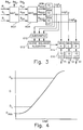
- the reference patch exposures are neutral. Referring to Fig.
- a photographic film strip 10 has image areas 12 exposed to a scene by means of camera 20.
- Reference patches 14 are exposed onto the photographic film strip 10 by the sensitometer 30.
- the sensitometer 30 may be positioned in the camera 20 to place the reference patches 14 onto the photographic film strip 10 either prior to or after the placement of images 12.
- the reference patches are placed onto the photographic film at the time of manufacture.
- a third preferred embodiment would place the reference patches onto the photographic film following removal from the camera, prior to photographic processing.
- the reference patches 14 may be placed at any region of the photographic film strip 10 that will not otherwise be exposed, such as the portion of the photographic film strip that does not come out of the film cartridge or the edge of the photographic film that is not within the image frame.
- the specified region of the photographic film strip 10 is reserved for recording reference patches.
- the reference patch exposure levels are chosen to be as different as possible while still falling within the total scale, and preferably within the linear response scale, of the photographic film strip 10, as shown in Fig. 4.
- the photographic film strip 10 is photographically processed in the processor 40 in the well known manner (e.g. C41, E6, etc.) following placement of all photographic images and reference patches onto the photographic film strip.
- the photographically processed film is then scanned by scanner 50 producing density representative digital signals which are forwarded to a computer 60 for processing.
- the processed digital signals are then forwarded to an output device 70.
- the output device 70 may take a number of forms such as a silver halide film or paper writer, thermal printer, electrophotographic printer, ink jet printer, CRT display, CD disc or other types of storage and display devices.
- FIG. 2 the processed photographic film strip 10 that is scanned by the scanner 50, is shown in more detail with a number of reference patches 14.
- the density representative digital signals from the scanner 50 obtained for reference patches 14 (R Pi , G Pi , B Pi ) and for the photographic image 12 (R i , G i , and B i ) are forwarded to the computer 60.
- the density representative digital signals of the reference patches 14 are compared with the standard film densities (R o i , G o i , B o i ) which are stored in a table 62 and originate from well manufactured, correctly stored and photographically processed film of the same photographic film type as film 10, given exposures which differ in intensity by the same amount as those used to obtain the reference patches 14 on the photographic film strip 10.
- the table 62 is to be populated with those standard film densities that correspond to the photographic film types that are to be processed by this technique.
- the comparison takes place in block 64. In the simplest form of the invention, only two reference patches 14 are used. The differences are used to calculate ⁇ correction values according to Eqs. 1-3.
- H and L refer to the high and low density reference patches, respectively, and the superscript " o " refers to the values for the standard film densities obtained with "well controlled (manufacturing, storage, and processing) conditions.”
- the gamma correction values are used in the further image processing block 66 of the density representative digital signals of the image 12 to provide the corrected red, green and blue exposure representative digital signals (E Ri , E Gi , E Bi ) to the output device 70.
- the details of processing block 66 are set forth in Fig. 3.
- FIG. 3 A typical image processing path is shown in Fig. 3.
- Density representative digital signals R i , G i , and B i from the image 12 are processed using a matrix 602.
- Matrix 602 is represented as follows: In its simplest form, the off diagonal elements (a 4 ⁇ a 9 ) of MAT ⁇ are all zero, and the diagonal elements, a 1 ⁇ a 3 , are ⁇ R , ⁇ G , and ⁇ B , respectively, and are calculated using Eqs. 1-3 for the photographic film strip 10 being processed. As shown in Eq.
- the matrix premultiplies the red, green and blue density representative digital signals of each scanned image 12 producing the gamma corrected density representative digital signals (R ⁇ c, G ⁇ c , B ⁇ c ).
- R ⁇ c i G ⁇ c i B ⁇ c i [MAT ⁇ ⁇ ] R i G i B i
- Further processing of the gamma corrected density representative digital signals with matrix 604 produces channel independent density representative digital signals (R ⁇ CID , G ⁇ CID , B ⁇ CID ).
- the red, green, and blue channel independent density representative digital signals are then converted to log exposure representative digital signals by the use of three one dimensional LUT's 606.
- the log exposure representative digital signals for the image 12 are subsampled in block 610 at a nominal rate of 1/256th of the full image resolution.
- a scene balance algorithm 612 is performed on the subsampled signals producing scene balance shift factors. The shift factors are added to the full resolution log exposure representative digital signals in the SBA blocks 614.
- Three one dimensional LUT's 616 convert the corrected log exposure representative digital signals to corresponding linear exposure representative digital signals.
- the linear exposure representative digital signals are pre-multiplied by a predetermined matrix (MAT 1) to form a second set of red, green, and blue linear exposure representative digital signals.
- Fig. 5 shows an alternative preferred form of the invention, which replaces image processing by components 604 through 616 with a single three dimensional LUT 620.
- a third reference density measurement is made in a region of the photographic film strip 10 which has received no exposure.
- Density representative digital signals for the unexposed region of the photographic film are obtained (R Dmin , G Dmin , and B Dmin ) from scanner 50.
- the resulting signals for the unexposed region of the photographic film are compared (Fig. 2, block 64) against standard film densities for an unexposed region of the photographic film (R 0 Dmin , G 0 Dmin , B 0 Dmin ) which are stored in a table 62 and originate from well manufactured, correctly stored and photographically processed photographic film of the same film type as film 10.
- the comparison takes place in block 64 where the differences are used to calculate D min correction values according to Eqs. 6-8.
- a further improvement in performance is obtained if the absolute levels of exposure used to produce the reference patches 14 on the photographic film strip 10 are known relative to those used to obtain the standard film densities (R 0 i , G 0 i , B 0 i ) which are stored in a table 62 and originate from well manufactured, correctly stored and photographically processed film of the same film type as film 10.
- Photographic speed values can be calculated using Eqs.
- Speed correction values are obtained by comparing the speed values determined for the scanned photographic film strip and those obtained from the standard film densities of well manufactured, correctly stored and photographically processed photographic film of the same film type as film 10, using Eqs. 12-14.
- the obtained speed correction values are subtracted from the log exposure representative digital signals of the scanned image resulting from LUT 606 in block 608 (Fig. 6).
- the speed corrected image signals improve the performance of the SBA 612 by allowing the subject failure suppression boundaries to be adjusted for better differentiation of hue shifts due to the illuminant and those resulting from elements in the image, producing superior reproductions of the recorded scene.
- the invention can be practiced with as few as two reference patches, other preferred embodiments of the invention utilize a larger number of exposure patches of the same or different color.
- a larger number of reference patches for example, 20 levels, allow a more robust estimation of speed and ⁇ correction values, and the ability to correct for more specific changes in the relationship between density produced on the photographically processed film and input exposure.
- ⁇ and speed correction values are obtained by comparing the density representative digital signals determined for the references patches and the standard film densities using standard methods of regression.
- speed and gamma correction values are chosen for each record to minimize ⁇ R RMS , ⁇ G RMS , and ⁇ B RMS as defined in Eqs. 15-17, where the n reference patches fall within the total scale of the photographic film.
- Speed and ⁇ correction values obtained in this manner are applied to the scanned image signals as described above.
- Use of more than two reference patches allows a more reliable determination of the ⁇ correction values appropriate for the total scale of the photographic film and is less sensitive to the placement of the exposure levels within the total scale.
- An alternative and preferred method of applying correction values obtained from many reference patches is to replace the three one-dimensional LUT's 606 with the density-log exposure relationships obtained from the reference patch data.
- a further affect of variations in photographic film manufacturing, storage, and photographic processing is to alter the extent of density formation in one image record dependent on the extent of density formation in at least one of the remaining image records.
- a preferred embodiment of the invention involves the use of multiple reference patches, each differing from the others in at least one attribute of color and intensity.
- the density representative digital signals obtained from scanning the multiple reference patches are compared with standard film densities which are stored in a table 62 and originate from well manufactured, correctly stored and photographically processed film of the same photographic film type as film 10.
- the nine elements of matrix 602 (MAT ⁇ ) are determined by standard methods of regression to minimize the differences ( ⁇ R RMS , Eq. 19) between the signals obtained from the reference patches when processed with matrix 602 (Eq. 18) and the standard film densities.
- Equations 1, 4, 5, and 6 were used to calculate ⁇ correction values, D min correction values, and speed correction values, using two reference patches which differed in intensity by 1.0 log exposure units.
- the lower reference patch exposure level was placed at a density of approximately 0.2 above D min for each photographic film type when photographically processed under the normal conditions.
- the ⁇ , speed, and D min correction values calculated with the two point method for the three films, processed with the high and low activity photographic processing conditions, are shown in Table 1.
- the complete set of neutral reference exposures was alternately used to calculate ⁇ correction values, Dmin correction values, and speed correction values, using standard methods of regression.
- the complete set of reference patches was used to determine the nine elements of matrix 602 by standard methods of regression.
- the correction matrices 602 for the three films, processed with the high and low activity photographic processing conditions, are shown in Table 2.
- the scanned density representative digital signals for the recorded scene were processed according to the image processing schemes shown in Fig. 3 or Fig. 6.
- the resulting exposure representative digital signals were used to drive a digital exposing device using silver halide photographic paper to make prints.
- Sets of reference prints for the three films were produced in the same manner, using the density representative digital signals from the strips processed with the standard activity process, and processing according to the image processing schemes shown in Fig. 3, excluding MAT ⁇ 602.
- the images were compared in two ways: by comparing the exposure representative digital signals for the images following image processing with and without correction according to the invention, and by visually comparing the associated silver halide prints produced.
- the exposure representative digital signals were compared by calculating the average root mean squared difference according to Eq. 20, where the summation is conducted over the i pixels and j color records of the image and E N ij corresponds to the exposure representative digital signals for the photographic film image produced using normal photographic processing conditions and a standard scene balance algorithm, and E C ij corresponds to exposure representative digital signals for the photographic film image produced using non-standard photographic processing conditions, after applying the digital correction values according to the invention.
- the visual comparison utilized a panel of five observers who compared the prepared photographic prints for overall image quality. Excellent correlation was found between the trends observed in comparing the exposure representative digital signals, and the ranking of the images for quality by the panel of judges; increased print quality was observed as the magnitude of the RMS difference decreased.
- ⁇ correction matrix 602 the scene balance algorithm is seen to substantially correct for the high activity process variations (smaller RMS value in Table 3, relative to the RMS value without implementation of the SBA). Inclusion of ⁇ correction matrix 602 is seen to significantly decrease variation due to the high activity photographic process. This results in significantly improved final image quality when ⁇ correction is employed, compared with images where only the scene balance algorithm is used.
- Table 3 RMS Difference Between Exposure Representative Image Signals for Photographic Film Photographically Processed Under Normal and High Activity Conditions Image Processing Conditions Color Negative Film #2 High Activity Chemical Process Without SBA 612 40.85 With SBA 612 10.55 With ⁇ Correction 602 (diagonal elements only) and SBA 612 4.84 Example 2 .
- Table 4 shows the results obtained for color negative films #1, #2 and #3, each photographically processed under the high activity chemical process.
- image processed including a current scene balance algorithm images from all three photographic films are substantially improved for the high activity process (smaller RMS values in Table 4, relative to the RMS value without implementation of the SBA).
- Image processing of the density representative digital signals according to Fig. 6, including ⁇ correction matrix 602 and speed correction block 608, as well as the scene balance algorithm 612, is seen to significantly decrease variation due to the high activity photographic processing, relative to use of the SBA alone, resulting in significantly improved quality of the final images.
- Table 4 RMS Difference Between Exposure Representative Image Signals for Photographic Film Photographically Processed Under Normal and High Activity Conditions Image Processing Conditions Color Negative Film #1 Color Negative Film #2 Color Negative Film #3 High Activity Chemical Process Without SBA 612 58.23 40.85 52.51 With SBA 612 11.43 10.55 14.54 With ⁇ correction 602 (diagonal elements only) speed correction 608, and SBA 612 10.62 5.62 8.84 Example 3 .
- Table 5 shows the results obtained for color negative film #3, photographically processed using the low activity chemical process.
- Image processing of the density representative digital signals including a current scene balance algorithm, substantially improved image quality for the low activity process (smaller RMS values in Table 5, relative to the RMS value without implementation of the SBA). Image processing of the density representative digital signals according to Fig.
- ⁇ correction matrix 602 and speed correction block 608, as well as the scene balance algorithm 612 is seen to significantly decrease variation due to the low activity photographic processing, relative to use of the SBA alone, resulting in significantly improved quality of the final images.
- Table 5 RMS Difference Between Exposure Representative Image Signals for Photographic Film Photographically Processed Under Normal and Low Activity Conditions. Image Processing Conditions Color Negative Film #3 Low Activity Chemical Process Without SBA 612 37.85 With SBA 612 15.38 With ⁇ Correction 602 (diagonal elements only), speed correction 608, and SBA 612 9.48 Example 4 .
- the gamma correction values, speed correction values and D min correction values were recalculated using standard regression techniques.
- the RMS values obtained are substantially the same as those shown in Tables 4 and 5. Again the image processing described in Fig 6. is seen to significantly decrease variation due to both the high and low activity photographic processing, relative to use of the SBA alone, resulting in significantly improved quality of the final images.
- Example 5 shows the results obtained for color negative films #1, #2, and #3, photographically processed using the high activity chemical process.
- RMS values are shown for images from the three films in which density representative digital signals were image processed including a current scene balance algorithm, and in which the same images are image processed according to Fig. 6, including ⁇ correction matrix 602 and speed correction block 608, as well as the scene balance algorithm 612, reproducing Table 4.
- the density representative digital signals from the same images are image processed according to Fig. 6, including ⁇ correction matrix 602 using ⁇ correction matrices from Table 2 rather than the simple diagonal ⁇ correction values from Table 1, speed correction block 608, and scene balance algorithm 612.
- the ⁇ correction matrix is shown to further significantly decrease variation caused by the high activity photographic process for film #1, resulting in significantly improved quality of the final images for this film.
Landscapes
- Physics & Mathematics (AREA)
- General Physics & Mathematics (AREA)
- Spectroscopy & Molecular Physics (AREA)
- Facsimile Image Signal Circuits (AREA)
- Color Image Communication Systems (AREA)
- Control Of Exposure In Printing And Copying (AREA)
- Image Processing (AREA)
Applications Claiming Priority (4)
| Application Number | Priority Date | Filing Date | Title |
|---|---|---|---|
| US7036 | 1987-01-27 | ||
| US703695P | 1995-10-25 | 1995-10-25 | |
| US636076 | 1996-04-22 | ||
| US08/636,076 US5667944A (en) | 1995-10-25 | 1996-04-22 | Digital process sensitivity correction |
Publications (2)
| Publication Number | Publication Date |
|---|---|
| EP0770905A2 true EP0770905A2 (de) | 1997-05-02 |
| EP0770905A3 EP0770905A3 (de) | 1998-06-24 |
Family
ID=26676390
Family Applications (1)
| Application Number | Title | Priority Date | Filing Date |
|---|---|---|---|
| EP96202826A Withdrawn EP0770905A3 (de) | 1995-10-25 | 1996-10-10 | Digitale Korrektur für eine Behandlungsempfindlichkeit |
Country Status (3)
| Country | Link |
|---|---|
| US (1) | US5667944A (de) |
| EP (1) | EP0770905A3 (de) |
| JP (1) | JPH09197577A (de) |
Cited By (9)
| Publication number | Priority date | Publication date | Assignee | Title |
|---|---|---|---|---|
| WO2000004492A3 (en) * | 1998-07-15 | 2001-10-25 | Imation Corp | Imaging system and method |
| EP1164430A1 (de) * | 2000-06-13 | 2001-12-19 | Eastman Kodak Company | Behandlungsgerät und Verfahren zur Bestimmung optimaler Behandlungsbedingungen |
| EP1180720A1 (de) * | 2000-08-09 | 2002-02-20 | Eastman Kodak Company | Eichungszonen |
| EP0961484A3 (de) * | 1998-05-28 | 2002-04-24 | Eastman Kodak Company | Digitales Fotobehandlungssystem mit digitaler Bildverarbeitung |
| EP0961485A3 (de) * | 1998-05-28 | 2002-04-24 | Eastman Kodak Company | Digitales Fotobehandlungssystem mit digitaler Bildverarbeitung |
| EP0961483A3 (de) * | 1998-05-28 | 2002-05-15 | Eastman Kodak Company | Digitales Fotobehandlungssystem mit digitaler Bildverarbeitung |
| WO2004019604A1 (en) * | 2002-08-23 | 2004-03-04 | Kodak Polychrome Graphics, Llc | Color profiling using gray backing material |
| EP0961482B1 (de) * | 1998-05-28 | 2007-12-12 | Eastman Kodak Company | Digitales Fotobehandlungssystem mit digitaler Bildverarbeitung von alternativen Medien für Farbfotos |
| WO2012051486A1 (en) * | 2010-10-15 | 2012-04-19 | Thomson Licensing | Method and system for producing video archive on film |
Families Citing this family (76)
| Publication number | Priority date | Publication date | Assignee | Title |
|---|---|---|---|---|
| US6590996B1 (en) * | 2000-02-14 | 2003-07-08 | Digimarc Corporation | Color adaptive watermarking |
| US6069714A (en) | 1996-12-05 | 2000-05-30 | Applied Science Fiction, Inc. | Method and apparatus for reducing noise in electronic film development |
| US6017688A (en) | 1997-01-30 | 2000-01-25 | Applied Science Fiction, Inc. | System and method for latent film recovery in electronic film development |
| US6243133B1 (en) * | 1997-03-07 | 2001-06-05 | Eastman Kodak Company | Method for automatic scene balance of digital images |
| JPH10307361A (ja) * | 1997-05-08 | 1998-11-17 | Fuji Photo Film Co Ltd | ハロゲン化銀写真感光材料及び該感光材料の画像形成方法 |
| US6512601B1 (en) | 1998-02-23 | 2003-01-28 | Applied Science Fiction, Inc. | Progressive area scan in electronic film development |
| JPH11298736A (ja) | 1998-04-14 | 1999-10-29 | Minolta Co Ltd | 画像処理方法、画像処理プログラムが記録された可読記録媒体及び画像処理装置 |
| JP3451202B2 (ja) | 1998-08-19 | 2003-09-29 | 富士写真フイルム株式会社 | 画像処理方法 |
| US6594041B1 (en) | 1998-11-20 | 2003-07-15 | Applied Science Fiction, Inc. | Log time processing and stitching system |
| US6278510B1 (en) * | 1998-12-07 | 2001-08-21 | Eastman Kodak Company | System for optical writing to thermal film |
| US6048110A (en) * | 1998-12-07 | 2000-04-11 | Eastman Kodak Company | Compact thermal film apparatus with magnetic sensing device |
| US6062746A (en) * | 1998-12-07 | 2000-05-16 | Eastman Kodak Company | Compact apparatus for thermal film development and scanning |
| US7355746B2 (en) * | 1999-02-12 | 2008-04-08 | Eastman Kodak Company | Method and apparatus for printing and/or displaying digital images |
| US6404516B1 (en) | 1999-02-22 | 2002-06-11 | Applied Science Fiction, Inc. | Parametric image stitching |
| US6295115B1 (en) * | 1999-03-01 | 2001-09-25 | Hewlett-Packard Company | Producing an optimized color image from a negative image and its developed print image |
| US6781620B1 (en) | 1999-03-16 | 2004-08-24 | Eastman Kodak Company | Mixed-element stitching and noise reduction system |
| TW495389B (en) | 1999-06-29 | 2002-07-21 | Applied Science Fiction Inc | Slot coater device for applying developer to film for electronic film development |
| WO2001013174A1 (en) * | 1999-08-17 | 2001-02-22 | Applied Science Fiction, Inc. | Method and system for using calibration patches in electronic film processing |
| US6302599B1 (en) | 1999-09-01 | 2001-10-16 | Eastman Kodak Company | Thermal film camera with processing |
| US6628826B1 (en) * | 1999-11-29 | 2003-09-30 | Eastman Kodak Company | Color reproduction of images from color films |
| WO2001045042A1 (en) * | 1999-12-17 | 2001-06-21 | Applied Science Fiction, Inc. | Method and system for selective enhancement of image data |
| US20010030685A1 (en) * | 1999-12-30 | 2001-10-18 | Darbin Stephen P. | Method and apparatus for digital film processing using a scanning station having a single sensor |
| US6813392B2 (en) | 1999-12-30 | 2004-11-02 | Eastman Kodak Company | Method and apparatus for aligning multiple scans of the same area of a medium using mathematical correlation |
| US6707557B2 (en) | 1999-12-30 | 2004-03-16 | Eastman Kodak Company | Method and system for estimating sensor dark current drift and sensor/illumination non-uniformities |
| US6540416B2 (en) * | 1999-12-30 | 2003-04-01 | Applied Science Fiction, Inc. | System and method for digital film development using visible light |
| AU2742701A (en) | 1999-12-30 | 2001-07-16 | Applied Science Fiction, Inc. | Improved system and method for digital film development using visible light |
| US6788335B2 (en) | 1999-12-30 | 2004-09-07 | Eastman Kodak Company | Pulsed illumination signal modulation control & adjustment method and system |
| US6864973B2 (en) | 1999-12-30 | 2005-03-08 | Eastman Kodak Company | Method and apparatus to pre-scan and pre-treat film for improved digital film processing handling |
| US6447178B2 (en) | 1999-12-30 | 2002-09-10 | Applied Science Fiction, Inc. | System, method, and apparatus for providing multiple extrusion widths |
| US6505977B2 (en) | 1999-12-30 | 2003-01-14 | Applied Science Fiction, Inc. | System and method for digital color dye film processing |
| AU2463501A (en) * | 1999-12-30 | 2001-07-24 | Applied Science Fiction, Inc. | Methods and apparatus for transporting and positioning film in a digital film processing system |
| US6965692B1 (en) | 1999-12-30 | 2005-11-15 | Eastman Kodak Company | Method and apparatus for improving the quality of reconstructed information |
| US6554504B2 (en) | 1999-12-30 | 2003-04-29 | Applied Science Fiction, Inc. | Distributed digital film processing system and method |
| WO2001050192A1 (en) * | 1999-12-31 | 2001-07-12 | Applied Science Fiction, Inc. | Digital film processing method |
| US6475711B1 (en) | 1999-12-31 | 2002-11-05 | Applied Science Fiction, Inc. | Photographic element and digital film processing method using same |
| US20010040701A1 (en) * | 2000-02-03 | 2001-11-15 | Edgar Albert D. | Photographic film having time resolved sensitivity distinction |
| AU2001236693A1 (en) | 2000-02-03 | 2001-08-14 | Applied Science Fiction | Film processing solution cartridge and method for developing and digitizing film |
| AU2001238021A1 (en) | 2000-02-03 | 2001-08-14 | Applied Science Fiction | Match blur system and method |
| US6786655B2 (en) | 2000-02-03 | 2004-09-07 | Eastman Kodak Company | Method and system for self-service film processing |
| US6619863B2 (en) | 2000-02-03 | 2003-09-16 | Eastman Kodak Company | Method and system for capturing film images |
| AU2001238039A1 (en) | 2000-02-03 | 2001-08-14 | Applied Science Fiction | Method, system and software for signal processing using sheep and shepherd artifacts |
| WO2001057796A2 (en) | 2000-02-03 | 2001-08-09 | Applied Science Fiction | Method, system, and software for signal processing using pyramidal decomposition |
| US6190844B1 (en) * | 2000-02-28 | 2001-02-20 | Eastman Kodak Company | Method of providing digital image in radiographic film having visually adaptive contrast |
| US6369873B1 (en) | 2000-06-13 | 2002-04-09 | Eastman Kodak Company | Thermal processing system and method including a kiosk |
| US20060182337A1 (en) * | 2000-06-28 | 2006-08-17 | Ford Benjamin C | Method and apparatus for improving the quality of reconstructed information |
| US6866199B1 (en) * | 2000-08-09 | 2005-03-15 | Eastman Kodak Company | Method of locating a calibration patch in a reference calibration target |
| US6985270B1 (en) * | 2000-08-09 | 2006-01-10 | Eastman Kodak Company | Method and photographic element for calibrating digital images |
| US6280914B1 (en) | 2000-08-09 | 2001-08-28 | Eastman Kodak Company | Photographic element with reference calibration data |
| US6407767B1 (en) | 2000-08-09 | 2002-06-18 | Eastman Kodak Company | Apparatus for exposing sensitometric and bar code data onto photosensitive media |
| US7113627B1 (en) * | 2000-08-09 | 2006-09-26 | Eastman Kodak Company | Location of extended linear defects |
| US6456798B1 (en) | 2000-08-09 | 2002-09-24 | Eastman Kodak Company | Barcode and data storage arrangement on a photographic element |
| US20020118402A1 (en) * | 2000-09-19 | 2002-08-29 | Shaw Timothy C. | Film bridge for digital film scanning system |
| US20020176113A1 (en) * | 2000-09-21 | 2002-11-28 | Edgar Albert D. | Dynamic image correction and imaging systems |
| US20020146171A1 (en) * | 2000-10-01 | 2002-10-10 | Applied Science Fiction, Inc. | Method, apparatus and system for black segment detection |
| US6888997B2 (en) * | 2000-12-05 | 2005-05-03 | Eastman Kodak Company | Waveguide device and optical transfer system for directing light to an image plane |
| US6985253B2 (en) * | 2000-12-28 | 2006-01-10 | Eastman Kodak Company | Processing film images for digital cinema |
| JP2004523793A (ja) | 2001-02-09 | 2004-08-05 | イーストマン コダック カンパニー | デジタルフィルム処理液およびデジタルフィルムの処理方法 |
| US20030002088A1 (en) * | 2001-06-27 | 2003-01-02 | O'hara James E. | Method for enhancing image output quality employing product data included on an image bearing media |
| US6805501B2 (en) * | 2001-07-16 | 2004-10-19 | Eastman Kodak Company | System and method for digital film development using visible light |
| US7263240B2 (en) * | 2002-01-14 | 2007-08-28 | Eastman Kodak Company | Method, system, and software for improving signal quality using pyramidal decomposition |
| US6520694B1 (en) | 2002-01-18 | 2003-02-18 | Eastman Kodak Company | System and method for processing photographic film images |
| FR2837007B1 (fr) * | 2002-03-07 | 2004-06-11 | Eastman Kodak Co | Procede pour l'obtention d'un temoin sensitometrique a gradient d'exposition et element photographique comprenant un tel temoin |
| FR2837006B1 (fr) | 2002-03-07 | 2004-11-05 | Eastman Kodak Co | Systeme d'exposition pour l'obtention d'un temoin sensitometrique a gradient d'exposition |
| DE10240860B4 (de) * | 2002-09-04 | 2008-07-03 | Calibr8 Gesellschaft für digitales Farbmanagement mbH | Vorrichtung und Verfahren zur automatisierten Kalibrierung digitaler Eingabegeräte |
| FR2846414B1 (fr) * | 2002-10-24 | 2005-01-07 | Eastman Kodak Co | Procede d'etablissement d'une courbe de sensitometrie d'un support photographique |
| US7254324B2 (en) * | 2003-08-11 | 2007-08-07 | Ujwal Narayan Nirgudkar | Systems and methods for film processing quality control |
| FR2861874B1 (fr) * | 2003-10-29 | 2006-02-24 | Eastman Kodak Co | Procede d'enregistrement et de lecture de donnees numeriques sur un support photographique |
| US6917758B1 (en) * | 2003-12-19 | 2005-07-12 | Eastman Kodak Company | Method of image compensation for watermarked film |
| US7522316B2 (en) * | 2003-12-19 | 2009-04-21 | Clemens Beisch | Device and method for automated calibration of digital input devices |
| CN100490505C (zh) * | 2004-02-13 | 2009-05-20 | 索尼株式会社 | 图像处理装置和图像处理方法 |
| DE102004038554A1 (de) | 2004-08-06 | 2006-03-16 | Thomson Broadcast And Media Solutions Gmbh | Filmbelichter und Verfahren zur Belichtung von lichtempfindlichen Filmen |
| US7885458B1 (en) * | 2005-10-27 | 2011-02-08 | Nvidia Corporation | Illuminant estimation using gamut mapping and scene classification |
| US8564687B2 (en) * | 2007-05-07 | 2013-10-22 | Nvidia Corporation | Efficient determination of an illuminant of a scene |
| US8698917B2 (en) * | 2007-06-04 | 2014-04-15 | Nvidia Corporation | Reducing computational complexity in determining an illuminant of a scene |
| KR101310216B1 (ko) * | 2009-12-21 | 2013-09-24 | 한국전자통신연구원 | 촬영된 영상의 컬러 변환 장치 및 방법 |
| US9870598B2 (en) | 2013-04-26 | 2018-01-16 | Nvidia Corporation | Low complexity adaptive filtering for mobile captures |
Family Cites Families (10)
| Publication number | Priority date | Publication date | Assignee | Title |
|---|---|---|---|---|
| US3718074A (en) * | 1971-05-13 | 1973-02-27 | R Davis | Color data acquisition camera |
| JPS5983144A (ja) * | 1982-11-02 | 1984-05-14 | Fuji Photo Film Co Ltd | 写真フイルムの測光条件修正方法 |
| JPS627290A (ja) * | 1985-07-04 | 1987-01-14 | Fuji Photo Film Co Ltd | カラ−ネガフイルム撮像における階調補正方法および装置 |
| US4977521A (en) * | 1988-07-25 | 1990-12-11 | Eastman Kodak Company | Film noise reduction by application of bayes theorem to positive/negative film |
| US5227837A (en) * | 1989-05-12 | 1993-07-13 | Fuji Photo Film Co., Ltd. | Photograph printing method |
| US5060061A (en) * | 1989-06-30 | 1991-10-22 | Victor Company Of Japan, Ltd. | Method of reading an image recorded in a photographic film tone characteristic correcting method in reproducing an image recorded in a photographic film |
| US5051341A (en) * | 1989-10-20 | 1991-09-24 | Eastman Kodak Company | Color imaging process and apparatus |
| JPH0722337B2 (ja) * | 1990-01-08 | 1995-03-08 | 富士ゼロックス株式会社 | 画像処理装置におけるフィルム画像パラメータ抽出方式 |
| US5300381A (en) * | 1992-09-24 | 1994-04-05 | Eastman Kodak Company | Color image reproduction of scenes with preferential tone mapping |
| US5500316A (en) * | 1994-12-05 | 1996-03-19 | Eastman Kodak Company | Color negative film with contrast adjusted for electronic scanning |
-
1996
- 1996-04-22 US US08/636,076 patent/US5667944A/en not_active Expired - Lifetime
- 1996-10-10 EP EP96202826A patent/EP0770905A3/de not_active Withdrawn
- 1996-10-15 JP JP8272745A patent/JPH09197577A/ja active Pending
Cited By (12)
| Publication number | Priority date | Publication date | Assignee | Title |
|---|---|---|---|---|
| EP0961484A3 (de) * | 1998-05-28 | 2002-04-24 | Eastman Kodak Company | Digitales Fotobehandlungssystem mit digitaler Bildverarbeitung |
| EP0961485A3 (de) * | 1998-05-28 | 2002-04-24 | Eastman Kodak Company | Digitales Fotobehandlungssystem mit digitaler Bildverarbeitung |
| EP0961483A3 (de) * | 1998-05-28 | 2002-05-15 | Eastman Kodak Company | Digitales Fotobehandlungssystem mit digitaler Bildverarbeitung |
| EP0961482B1 (de) * | 1998-05-28 | 2007-12-12 | Eastman Kodak Company | Digitales Fotobehandlungssystem mit digitaler Bildverarbeitung von alternativen Medien für Farbfotos |
| WO2000004492A3 (en) * | 1998-07-15 | 2001-10-25 | Imation Corp | Imaging system and method |
| EP1164430A1 (de) * | 2000-06-13 | 2001-12-19 | Eastman Kodak Company | Behandlungsgerät und Verfahren zur Bestimmung optimaler Behandlungsbedingungen |
| US6490023B1 (en) | 2000-06-13 | 2002-12-03 | Eastman Kodak Company | Processing apparatus and method for determining optimum processing characteristics of thermal developable film |
| EP1180720A1 (de) * | 2000-08-09 | 2002-02-20 | Eastman Kodak Company | Eichungszonen |
| WO2004019604A1 (en) * | 2002-08-23 | 2004-03-04 | Kodak Polychrome Graphics, Llc | Color profiling using gray backing material |
| US7016042B2 (en) | 2002-08-23 | 2006-03-21 | Eastman Kodak Company | Color profiling using gray backing material |
| WO2012051486A1 (en) * | 2010-10-15 | 2012-04-19 | Thomson Licensing | Method and system for producing video archive on film |
| WO2012051483A3 (en) * | 2010-10-15 | 2012-08-02 | Thomson Licensing | Method and system of archiving video to film |
Also Published As
| Publication number | Publication date |
|---|---|
| JPH09197577A (ja) | 1997-07-31 |
| EP0770905A3 (de) | 1998-06-24 |
| US5667944A (en) | 1997-09-16 |
Similar Documents
| Publication | Publication Date | Title |
|---|---|---|
| US5667944A (en) | Digital process sensitivity correction | |
| US6956967B2 (en) | Color transformation for processing digital images | |
| EP0813336B1 (de) | Bildverarbeitungsverfahren und -gerät | |
| EP0961484B1 (de) | Digitales Fotobehandlungssystem mit digitaler Bildverarbeitung | |
| US4729016A (en) | Digital color image processing method and apparatus employing three color reproduction functions for adjusting both tone scale and color balance | |
| EP0961482B1 (de) | Digitales Fotobehandlungssystem mit digitaler Bildverarbeitung von alternativen Medien für Farbfotos | |
| US6233069B1 (en) | Digital photofinishing system including film under exposure gamma, scene balance, contrast normalization, and image sharpening digital image processing | |
| EP0619674A2 (de) | Verfahren und Vorrichtung zur Herstellung farbiger Internegativen mit einem Farbdrucker | |
| EP0961486B1 (de) | Digitales Fotobehandlungssystem mit digitaler Bildverarbeitung | |
| US6163389A (en) | Digital photofinishing system including digital image processing of alternative capture color photographic media | |
| EP1377031A2 (de) | Erweiterung des dynamischen Bereichs und Einstellung der Farbmerkmale eines digitalen Bildes | |
| US5995194A (en) | Reproducing machine and a method of determining reproducing conditions | |
| EP0940773B1 (de) | Bilverarbeitungsverfahren und -vorrichtung | |
| US5966505A (en) | Image outputting method and converting information producing method | |
| US5790280A (en) | Digital image recording method and apparatus therefor and digital image processing apparatus | |
| US6917758B1 (en) | Method of image compensation for watermarked film | |
| US6614945B1 (en) | Image processing method and apparatus | |
| US6882451B2 (en) | Method and means for determining estimated relative exposure values from optical density values of photographic media | |
| JP3530640B2 (ja) | デジタル画像記録方法及び装置並びにデジタル画像処理装置 | |
| JP3614541B2 (ja) | デジタルプリンタ及びこれの画像データ変換方法、画像記録方法 | |
| JPH10224650A5 (de) | ||
| JPH09181919A (ja) | デジタルプリンタ及びこれの画像データ変換方法 | |
| JPH10224650A (ja) | 画像処理方法及び装置 | |
| JPH0965139A (ja) | デジタル画像記録方法及び装置並びにデジタル画像処理装置 | |
| JPH09181918A (ja) | デジタルプリンタの画像データ変換方法 |
Legal Events
| Date | Code | Title | Description |
|---|---|---|---|
| PUAI | Public reference made under article 153(3) epc to a published international application that has entered the european phase |
Free format text: ORIGINAL CODE: 0009012 |
|
| AK | Designated contracting states |
Kind code of ref document: A2 Designated state(s): DE FR GB |
|
| PUAL | Search report despatched |
Free format text: ORIGINAL CODE: 0009013 |
|
| AK | Designated contracting states |
Kind code of ref document: A3 Designated state(s): DE FR GB |
|
| 17P | Request for examination filed |
Effective date: 19980928 |
|
| 17Q | First examination report despatched |
Effective date: 20020527 |
|
| GRAP | Despatch of communication of intention to grant a patent |
Free format text: ORIGINAL CODE: EPIDOSNIGR1 |
|
| STAA | Information on the status of an ep patent application or granted ep patent |
Free format text: STATUS: THE APPLICATION IS DEEMED TO BE WITHDRAWN |
|
| 18D | Application deemed to be withdrawn |
Effective date: 20040430 |