EP0773057B1 - Catalyseur pour la purification de gaz d'échappement - Google Patents
Catalyseur pour la purification de gaz d'échappement Download PDFInfo
- Publication number
- EP0773057B1 EP0773057B1 EP96117850A EP96117850A EP0773057B1 EP 0773057 B1 EP0773057 B1 EP 0773057B1 EP 96117850 A EP96117850 A EP 96117850A EP 96117850 A EP96117850 A EP 96117850A EP 0773057 B1 EP0773057 B1 EP 0773057B1
- Authority
- EP
- European Patent Office
- Prior art keywords
- exhaust gas
- catalyst
- zeolite
- gas purifying
- inflowing
- Prior art date
- Legal status (The legal status is an assumption and is not a legal conclusion. Google has not performed a legal analysis and makes no representation as to the accuracy of the status listed.)
- Expired - Lifetime
Links
Images

Classifications
-
- F—MECHANICAL ENGINEERING; LIGHTING; HEATING; WEAPONS; BLASTING
- F01—MACHINES OR ENGINES IN GENERAL; ENGINE PLANTS IN GENERAL; STEAM ENGINES
- F01N—GAS-FLOW SILENCERS OR EXHAUST APPARATUS FOR MACHINES OR ENGINES IN GENERAL; GAS-FLOW SILENCERS OR EXHAUST APPARATUS FOR INTERNAL-COMBUSTION ENGINES
- F01N3/00—Exhaust or silencing apparatus having means for purifying, rendering innocuous, or otherwise treating exhaust
- F01N3/08—Exhaust or silencing apparatus having means for purifying, rendering innocuous, or otherwise treating exhaust for rendering innocuous
- F01N3/10—Exhaust or silencing apparatus having means for purifying, rendering innocuous, or otherwise treating exhaust for rendering innocuous by thermal or catalytic conversion of noxious components of exhaust
-
- B—PERFORMING OPERATIONS; TRANSPORTING
- B01—PHYSICAL OR CHEMICAL PROCESSES OR APPARATUS IN GENERAL
- B01D—SEPARATION
- B01D53/00—Separation of gases or vapours; Recovering vapours of volatile solvents from gases; Chemical or biological purification of waste gases, e.g. engine exhaust gases, smoke, fumes, flue gases, aerosols
- B01D53/34—Chemical or biological purification of waste gases
- B01D53/92—Chemical or biological purification of waste gases of engine exhaust gases
- B01D53/94—Chemical or biological purification of waste gases of engine exhaust gases by catalytic processes
- B01D53/9404—Removing only nitrogen compounds
- B01D53/9409—Nitrogen oxides
- B01D53/9413—Processes characterised by a specific catalyst
- B01D53/9418—Processes characterised by a specific catalyst for removing nitrogen oxides by selective catalytic reduction [SCR] using a reducing agent in a lean exhaust gas
-
- B—PERFORMING OPERATIONS; TRANSPORTING
- B01—PHYSICAL OR CHEMICAL PROCESSES OR APPARATUS IN GENERAL
- B01D—SEPARATION
- B01D53/00—Separation of gases or vapours; Recovering vapours of volatile solvents from gases; Chemical or biological purification of waste gases, e.g. engine exhaust gases, smoke, fumes, flue gases, aerosols
- B01D53/34—Chemical or biological purification of waste gases
- B01D53/92—Chemical or biological purification of waste gases of engine exhaust gases
- B01D53/94—Chemical or biological purification of waste gases of engine exhaust gases by catalytic processes
- B01D53/9495—Controlling the catalytic process
-
- F—MECHANICAL ENGINEERING; LIGHTING; HEATING; WEAPONS; BLASTING
- F01—MACHINES OR ENGINES IN GENERAL; ENGINE PLANTS IN GENERAL; STEAM ENGINES
- F01N—GAS-FLOW SILENCERS OR EXHAUST APPARATUS FOR MACHINES OR ENGINES IN GENERAL; GAS-FLOW SILENCERS OR EXHAUST APPARATUS FOR INTERNAL-COMBUSTION ENGINES
- F01N13/00—Exhaust or silencing apparatus characterised by constructional features
- F01N13/009—Exhaust or silencing apparatus characterised by constructional features having two or more separate purifying devices arranged in series
-
- F—MECHANICAL ENGINEERING; LIGHTING; HEATING; WEAPONS; BLASTING
- F01—MACHINES OR ENGINES IN GENERAL; ENGINE PLANTS IN GENERAL; STEAM ENGINES
- F01N—GAS-FLOW SILENCERS OR EXHAUST APPARATUS FOR MACHINES OR ENGINES IN GENERAL; GAS-FLOW SILENCERS OR EXHAUST APPARATUS FOR INTERNAL-COMBUSTION ENGINES
- F01N13/00—Exhaust or silencing apparatus characterised by constructional features
- F01N13/009—Exhaust or silencing apparatus characterised by constructional features having two or more separate purifying devices arranged in series
- F01N13/0097—Exhaust or silencing apparatus characterised by constructional features having two or more separate purifying devices arranged in series the purifying devices are arranged in a single housing
-
- F—MECHANICAL ENGINEERING; LIGHTING; HEATING; WEAPONS; BLASTING
- F01—MACHINES OR ENGINES IN GENERAL; ENGINE PLANTS IN GENERAL; STEAM ENGINES
- F01N—GAS-FLOW SILENCERS OR EXHAUST APPARATUS FOR MACHINES OR ENGINES IN GENERAL; GAS-FLOW SILENCERS OR EXHAUST APPARATUS FOR INTERNAL-COMBUSTION ENGINES
- F01N3/00—Exhaust or silencing apparatus having means for purifying, rendering innocuous, or otherwise treating exhaust
- F01N3/08—Exhaust or silencing apparatus having means for purifying, rendering innocuous, or otherwise treating exhaust for rendering innocuous
- F01N3/0807—Exhaust or silencing apparatus having means for purifying, rendering innocuous, or otherwise treating exhaust for rendering innocuous by using absorbents or adsorbents
- F01N3/0828—Exhaust or silencing apparatus having means for purifying, rendering innocuous, or otherwise treating exhaust for rendering innocuous by using absorbents or adsorbents characterised by the absorbed or adsorbed substances
- F01N3/0842—Nitrogen oxides
-
- F—MECHANICAL ENGINEERING; LIGHTING; HEATING; WEAPONS; BLASTING
- F01—MACHINES OR ENGINES IN GENERAL; ENGINE PLANTS IN GENERAL; STEAM ENGINES
- F01N—GAS-FLOW SILENCERS OR EXHAUST APPARATUS FOR MACHINES OR ENGINES IN GENERAL; GAS-FLOW SILENCERS OR EXHAUST APPARATUS FOR INTERNAL-COMBUSTION ENGINES
- F01N3/00—Exhaust or silencing apparatus having means for purifying, rendering innocuous, or otherwise treating exhaust
- F01N3/08—Exhaust or silencing apparatus having means for purifying, rendering innocuous, or otherwise treating exhaust for rendering innocuous
- F01N3/10—Exhaust or silencing apparatus having means for purifying, rendering innocuous, or otherwise treating exhaust for rendering innocuous by thermal or catalytic conversion of noxious components of exhaust
- F01N3/105—General auxiliary catalysts, e.g. upstream or downstream of the main catalyst
- F01N3/106—Auxiliary oxidation catalysts
-
- F—MECHANICAL ENGINEERING; LIGHTING; HEATING; WEAPONS; BLASTING
- F01—MACHINES OR ENGINES IN GENERAL; ENGINE PLANTS IN GENERAL; STEAM ENGINES
- F01N—GAS-FLOW SILENCERS OR EXHAUST APPARATUS FOR MACHINES OR ENGINES IN GENERAL; GAS-FLOW SILENCERS OR EXHAUST APPARATUS FOR INTERNAL-COMBUSTION ENGINES
- F01N3/00—Exhaust or silencing apparatus having means for purifying, rendering innocuous, or otherwise treating exhaust
- F01N3/08—Exhaust or silencing apparatus having means for purifying, rendering innocuous, or otherwise treating exhaust for rendering innocuous
- F01N3/10—Exhaust or silencing apparatus having means for purifying, rendering innocuous, or otherwise treating exhaust for rendering innocuous by thermal or catalytic conversion of noxious components of exhaust
- F01N3/105—General auxiliary catalysts, e.g. upstream or downstream of the main catalyst
- F01N3/108—Auxiliary reduction catalysts
-
- B—PERFORMING OPERATIONS; TRANSPORTING
- B01—PHYSICAL OR CHEMICAL PROCESSES OR APPARATUS IN GENERAL
- B01D—SEPARATION
- B01D2255/00—Catalysts
- B01D2255/10—Noble metals or compounds thereof
- B01D2255/102—Platinum group metals
- B01D2255/1021—Platinum
-
- B—PERFORMING OPERATIONS; TRANSPORTING
- B01—PHYSICAL OR CHEMICAL PROCESSES OR APPARATUS IN GENERAL
- B01D—SEPARATION
- B01D2255/00—Catalysts
- B01D2255/20—Metals or compounds thereof
- B01D2255/207—Transition metals
- B01D2255/20761—Copper
-
- B—PERFORMING OPERATIONS; TRANSPORTING
- B01—PHYSICAL OR CHEMICAL PROCESSES OR APPARATUS IN GENERAL
- B01D—SEPARATION
- B01D2255/00—Catalysts
- B01D2255/50—Zeolites
-
- B—PERFORMING OPERATIONS; TRANSPORTING
- B01—PHYSICAL OR CHEMICAL PROCESSES OR APPARATUS IN GENERAL
- B01D—SEPARATION
- B01D2255/00—Catalysts
- B01D2255/90—Physical characteristics of catalysts
- B01D2255/911—NH3-storage component incorporated in the catalyst
-
- B—PERFORMING OPERATIONS; TRANSPORTING
- B01—PHYSICAL OR CHEMICAL PROCESSES OR APPARATUS IN GENERAL
- B01D—SEPARATION
- B01D53/00—Separation of gases or vapours; Recovering vapours of volatile solvents from gases; Chemical or biological purification of waste gases, e.g. engine exhaust gases, smoke, fumes, flue gases, aerosols
- B01D53/34—Chemical or biological purification of waste gases
- B01D53/92—Chemical or biological purification of waste gases of engine exhaust gases
- B01D53/94—Chemical or biological purification of waste gases of engine exhaust gases by catalytic processes
- B01D53/9459—Removing one or more of nitrogen oxides, carbon monoxide, or hydrocarbons by multiple successive catalytic functions; systems with more than one different function, e.g. zone coated catalysts
- B01D53/9477—Removing one or more of nitrogen oxides, carbon monoxide, or hydrocarbons by multiple successive catalytic functions; systems with more than one different function, e.g. zone coated catalysts with catalysts positioned on separate bricks, e.g. exhaust systems
-
- F—MECHANICAL ENGINEERING; LIGHTING; HEATING; WEAPONS; BLASTING
- F01—MACHINES OR ENGINES IN GENERAL; ENGINE PLANTS IN GENERAL; STEAM ENGINES
- F01N—GAS-FLOW SILENCERS OR EXHAUST APPARATUS FOR MACHINES OR ENGINES IN GENERAL; GAS-FLOW SILENCERS OR EXHAUST APPARATUS FOR INTERNAL-COMBUSTION ENGINES
- F01N2240/00—Combination or association of two or more different exhaust treating devices, or of at least one such device with an auxiliary device, not covered by indexing codes F01N2230/00 or F01N2250/00, one of the devices being
- F01N2240/25—Combination or association of two or more different exhaust treating devices, or of at least one such device with an auxiliary device, not covered by indexing codes F01N2230/00 or F01N2250/00, one of the devices being an ammonia generator
-
- F—MECHANICAL ENGINEERING; LIGHTING; HEATING; WEAPONS; BLASTING
- F01—MACHINES OR ENGINES IN GENERAL; ENGINE PLANTS IN GENERAL; STEAM ENGINES
- F01N—GAS-FLOW SILENCERS OR EXHAUST APPARATUS FOR MACHINES OR ENGINES IN GENERAL; GAS-FLOW SILENCERS OR EXHAUST APPARATUS FOR INTERNAL-COMBUSTION ENGINES
- F01N2250/00—Combinations of different methods of purification
- F01N2250/12—Combinations of different methods of purification absorption or adsorption, and catalytic conversion
-
- F—MECHANICAL ENGINEERING; LIGHTING; HEATING; WEAPONS; BLASTING
- F01—MACHINES OR ENGINES IN GENERAL; ENGINE PLANTS IN GENERAL; STEAM ENGINES
- F01N—GAS-FLOW SILENCERS OR EXHAUST APPARATUS FOR MACHINES OR ENGINES IN GENERAL; GAS-FLOW SILENCERS OR EXHAUST APPARATUS FOR INTERNAL-COMBUSTION ENGINES
- F01N2370/00—Selection of materials for exhaust purification
- F01N2370/02—Selection of materials for exhaust purification used in catalytic reactors
- F01N2370/04—Zeolitic material
-
- F—MECHANICAL ENGINEERING; LIGHTING; HEATING; WEAPONS; BLASTING
- F01—MACHINES OR ENGINES IN GENERAL; ENGINE PLANTS IN GENERAL; STEAM ENGINES
- F01N—GAS-FLOW SILENCERS OR EXHAUST APPARATUS FOR MACHINES OR ENGINES IN GENERAL; GAS-FLOW SILENCERS OR EXHAUST APPARATUS FOR INTERNAL-COMBUSTION ENGINES
- F01N2570/00—Exhaust treating apparatus eliminating, absorbing or adsorbing specific elements or compounds
- F01N2570/14—Nitrogen oxides
-
- F—MECHANICAL ENGINEERING; LIGHTING; HEATING; WEAPONS; BLASTING
- F02—COMBUSTION ENGINES; HOT-GAS OR COMBUSTION-PRODUCT ENGINE PLANTS
- F02B—INTERNAL-COMBUSTION PISTON ENGINES; COMBUSTION ENGINES IN GENERAL
- F02B1/00—Engines characterised by fuel-air mixture compression
- F02B1/02—Engines characterised by fuel-air mixture compression with positive ignition
- F02B1/04—Engines characterised by fuel-air mixture compression with positive ignition with fuel-air mixture admission into cylinder
-
- F—MECHANICAL ENGINEERING; LIGHTING; HEATING; WEAPONS; BLASTING
- F02—COMBUSTION ENGINES; HOT-GAS OR COMBUSTION-PRODUCT ENGINE PLANTS
- F02D—CONTROLLING COMBUSTION ENGINES
- F02D41/00—Electrical control of supply of combustible mixture or its constituents
- F02D41/02—Circuit arrangements for generating control signals
- F02D41/021—Introducing corrections for particular conditions exterior to the engine
- F02D41/0235—Introducing corrections for particular conditions exterior to the engine in relation with the state of the exhaust gas treating apparatus
- F02D41/027—Introducing corrections for particular conditions exterior to the engine in relation with the state of the exhaust gas treating apparatus to purge or regenerate the exhaust gas treating apparatus
- F02D41/0275—Introducing corrections for particular conditions exterior to the engine in relation with the state of the exhaust gas treating apparatus to purge or regenerate the exhaust gas treating apparatus the exhaust gas treating apparatus being a NOx trap or adsorbent
-
- Y—GENERAL TAGGING OF NEW TECHNOLOGICAL DEVELOPMENTS; GENERAL TAGGING OF CROSS-SECTIONAL TECHNOLOGIES SPANNING OVER SEVERAL SECTIONS OF THE IPC; TECHNICAL SUBJECTS COVERED BY FORMER USPC CROSS-REFERENCE ART COLLECTIONS [XRACs] AND DIGESTS
- Y02—TECHNOLOGIES OR APPLICATIONS FOR MITIGATION OR ADAPTATION AGAINST CLIMATE CHANGE
- Y02A—TECHNOLOGIES FOR ADAPTATION TO CLIMATE CHANGE
- Y02A50/00—TECHNOLOGIES FOR ADAPTATION TO CLIMATE CHANGE in human health protection, e.g. against extreme weather
- Y02A50/20—Air quality improvement or preservation, e.g. vehicle emission control or emission reduction by using catalytic converters
-
- Y—GENERAL TAGGING OF NEW TECHNOLOGICAL DEVELOPMENTS; GENERAL TAGGING OF CROSS-SECTIONAL TECHNOLOGIES SPANNING OVER SEVERAL SECTIONS OF THE IPC; TECHNICAL SUBJECTS COVERED BY FORMER USPC CROSS-REFERENCE ART COLLECTIONS [XRACs] AND DIGESTS
- Y02—TECHNOLOGIES OR APPLICATIONS FOR MITIGATION OR ADAPTATION AGAINST CLIMATE CHANGE
- Y02T—CLIMATE CHANGE MITIGATION TECHNOLOGIES RELATED TO TRANSPORTATION
- Y02T10/00—Road transport of goods or passengers
- Y02T10/10—Internal combustion engine [ICE] based vehicles
- Y02T10/12—Improving ICE efficiencies
Definitions
- the present invention relates to a method of purifying an exhaust gas in an internal combustion engine.
- an exhaust gas purifying apparatus for an internal combustion engine with multi-cylinders in which an engine air-fuel ratio is controlled to a stoichiometric point, wherein a three-way catalyst is arranged in an exhaust passage connected to each cylinder, to bring nitrogen oxides NO x , hydrocarbon HC, and carbon monoxide CO, which are included in the exhaust gas, into contact with the three-way catalyst, to thereby reduce all components NO x , HC, and CO simultaneously.
- an air-fuel ratio of an air-fuel mixture in a combustion chamber of an internal combustion engine is referred to as an engine air-fuel ratio, hereinafter.
- Japanese unexamined patent publication No. 4-365920 discloses an exhaust gas purifying apparatus, for an internal combustion engine with multi-cylinders, the engine having a first and a second cylinder groups.
- the purifying apparatus is provided with: an engine operation control device to continuously make each cylinder of the first cylinder group perform a rich engine operation in which the engine air-fuel ratio is set rich with respect to the stoichiometric point, and to continuously make each cylinder of the second cylinder group perform a lean engine operation, in which the engine air-fuel ratio is set lean with respect to the stoichiometric point; a first exhaust passage connected to each cylinder of the first cylinder group; a second exhaust passage connected to each cylinder of the second cylinder group and different from the first exhaust passage; an ammonia synthesizing catalyst arranged in the first exhaust passage for synthesizing ammonia NH 3 from NO x in the inflowing exhaust gas; an interconnecting passage interconnecting the first exhaust passage downstream of the NH 3 synthesizing catalyst
- the fuel consumption rate is reduced by increasing the numbers of the cylinders of the second cylinder group in which the lean engine operation is performed, while NO x is sufficiently reduced by introducing the exhaust gas from the first cylinder group in which the rich engine operation is performed to thereby synthesize NH 3 , and by reacting this NH 3 and NO x from the second cylinder group at the exhaust gas purifying catalyst.
- the exhaust gas purifying catalyst may be a catalyst having a zeolite carrying cobalt Co, copper Cu, Nickel Ni, or iron Fe.
- a purifying temperature range hereinafter.
- the inflowing exhaust gas temperature varies outside the purifying temperature range.
- An additional device to cool or heat the exhaust gas inflowing the catalyst may keep the inflowing gas temperature within the purifying temperature range, but such an additional device may complicate the arrangement of the purifying apparatus, and may be costly.
- US-A-5,409,671 discloses a catalytic convertor for treating exhaust gas including a first catalyst layer formed on a base material and a second catalyst layer formed on the first catalyst layer.
- the first catalyst layer is composed of metal-containing silicate provided with transition metal by ion exchange and at least one noble metal on the silicate and the second catalyst layer is composed of metal-containing silicate provided with transition metal by ion exchange and at least one metal on the silicate.
- JP-A-6-190 246 identified by its English abstract discloses an apparatus for cleaning exhaust gas of a car having a first honeycomb catalyst based on a zeolite containing copper and phosphorus and a second honeycomb catalyst based on alumino silicate (zeolite) containing a noble metal.
- the first catalyst may optionally contain a noble metal such as platinum which may also be the noble metal of the second catalyst.
- Such an apparatus is useful for purifying an exhaust gas from hydrocarbons and nitrogen oxides in a wide range of stoichiometric oxygen content and lean atmosphere.
- An object of the present invention is to provide an exhaust gas purifying catalyst for reducing the amounts of nitrogen oxides and ammonia in an exhaust gas and sufficiently simultaneously, with a wider purifying temperature range.
- a method of purifying an exhaust gas of an internal combustion engine comprising providing an exhaust gas purifying catalyst comprising a first catalyst having zeolite carrying platinum and copper thereon introducing the exhaust gas including nitrogen oxide and ammonia into said first catalyst in an oxidizing atmosphere to simultaneously remove nitrogen oxides and ammonia in the exhaust gas under an oxidizing atmosphere.
- nitrogen oxides NO x include nitrogen monoxide NO, nitrogen dioxide NO 2 , dinitrogen tetroxide N 2 O 4 , dinitrogen monoxide N 2 O, etc.
- the following explanation is made by considering NO x to-mainly consist of nitrogen monoxide NO and/or nitrogen dioxide NO 2 , but an exhaust gas purifying catalyst according to the present invention can reduce other nitrogen oxides.
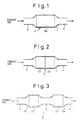
- the reference numeral 1 denotes a catalytic converter accommodating an exhaust gas purifying catalyst 2 applying the method according to the present invention therein.
- An inlet of the catalytic converter 1 is connected to an exhaust duct 3, and the duct 3 is connected to an internal combustion engine.
- An outlet of the catalytic converter 1 is connected to an exhaust duct 4.
- the catalyst 2 comprises a zeolite 2a, as a carrier, carrying both platinum Pt and copper Cu after an ion-changing process, and it is referred as a Pt-Cu zeolite catalyst, hereinafter.
- the Pt-Cu zeolite catalyst 2a is carried on the surface of a substrate in the form of, for example, honeycomb.
- silica rich zeolite may be used, such as ZSM-5 zeolite, ferrierite, mordenite, etc. Note that the Pt-Cu zeolite catalyst 2a is carried substantially over the entire surface of the substrate.
- the exhaust gas purifying catalyst 2 performs the reduction of NO x and the oxidation of NH 3 , when the exhaust gas including NO x and NH 3 contacts the catalyst 2 in an oxidizing atmosphere.
- the exhaust gas including NO x and NH 3 may be an exhaust gas including NO x and NH 3 mixedly, or an exhaust gas having two parts, one including NO x without including NH 3 , the other including NH 3 without including NO x , and the two parts inflowing alternately repeatedly. Also, if the exhaust gas inflowing the exhaust gas purifying catalyst 2 includes both of NO x and NH 3 , NO x oxidizes NH 3 .
- the above purifying mechanism has not been made clear, but it can be considered that the purifying mechanism is performed according to the following reactions (1) to (4), that is: 4NH 3 + 70 2 ⁇ 4NO 2 + 6H 2 O 4NH 3 + 50 2 ⁇ 4NO + 6H 2 O 8NH 3 + 6NO 2 ⁇ 12H 2 O + 7N 2 4NH 3 + 4NO + O 2 ⁇ 6H 2 O + 4N 2
- the reactions (3) and (4) which are denitration reactions, reduce both NO x produced in the oxidation reactions (1) and (2), and NO x flowing into the exhaust gas purifying catalyst 2. In this way, NO x and NH 3 are reduced simultaneously, at the catalyst 2.
- zeolite has an adsorbing and releasing function of NH 3 in which zeolite temporarily adsorbs NH 3 in the inflowing exhaust gas, and releases the adsorbed NH 3 .
- the absorbing and releasing mechanism of NH 3 of zeolite is also unclear but it can be considered that zeolite adsorbs NH 3 when the inflowing exhaust gas includes NH 3 , and releases the adsorbed NH 3 when the concentration of NH 3 in the inflowing exhaust gas becomes lower, or when the inflowing exhaust gas includes NO x .
- the released NH 3 reacts with NO x included in the inflowing exhaust gas to thereby be reduced.
- NH 3 in the inflowing exhaust gas is adsorbed in the catalyst 2 when the exhaust gas part including NH 3 without including NO x contacts with the catalyst 2, and NH 3 in the catalyst 2 is released when the exhaust gas part including NO x without including NH 3 contacts with the catalyst 2.
- the released NH 3 is decomposed by the oxidation reactions (1) and (2) mentioned above, in an oxidizing atmosphere, and NO x in the inflowing exhaust gas is reduced by the denitration reactions (3) and (4) mentioned above.
- the reduction of NO x and NH 3 can be observed when the exhaust gas including NO x and NH 3 contacts, in an oxidizing atmosphere, with a catalyst comprising a zeolite carrying copper Cu by the ion-changing process, which is referred to as the Cu zeolite catalyst, hereinafter.
- the inventors of the present invention have found that it is difficult for the Cu zeolite catalyst to reduce the amounts of NO x and NH 3 sufficiently simultaneously when the temperature of the exhaust gas inflowing the Cu zeolite catalyst is relatively low, for example, at about 100 to 200°C. That is, the large amount of NH 3 is exhausted from the Cu zeolite catalyst without being reduced, although the amount of NO x can be reduced sufficiently. It is considered that this is because the oxidizing ability of copper Cu at the low temperature is relatively weak, and the oxidizing reactions (1) and (2) mentioned above do not occur sufficiently, and thereby NH 3 is not oxidized sufficiently.
- the exhaust gas purifying catalyst 2 is formed as the Pt-Cu zeolite catalyst 2a.
- Platinum Pt has an adequate oxidizing ability even at the low temperature, and thus NH 3 is sufficiently oxidized even when the temperature of the inflowing exhaust gas is relatively low. Accordingly, the amounts of NO x and NH 3 are reduced simultaneously and sufficiently.
- an exhaust gas purifying catalyst 2 consisting of the Pt-Cu zeolite catalyst 2a decompose NH 3 sufficiently at a wider temperature range of the inflowing exhaust gas, for example, about 100 to 500°C, when contacting the exhaust gas including NH 3 without including NO x therewith.
- Fig. 2 shows another embodiment of the exhaust gas purifying catalyst 2 applying the method according to the present invention.
- constituent elements the same as those in Fig. 1 are given the same reference numerals.
- the exhaust gas purifying catalyst 2 comprises the Pt-Cu-zeolite catalyst 2a and the Cu zeolite catalyst 2b. Further, in this embodiment, the Pt-Cu zeolite catalyst 2a and the cu zeolite catalyst 2b are carried on the surface of the common substrate. Namely, the Pt-Cu zeolite catalyst 2a as in the embodiment shown in Fig. 1 is carried on the surface of a downstream portion of the substrate with respect to the exhaust gas flow, and the Cu zeolite catalyst 2b is carried on the surface of an upstream portion of the substrate. Note that the Cu zeolite catalyst 2b is formed of a silica rich zeolite carrying copper Cu after an ion-changing process.
- the exhaust gas purifying catalyst 2 also reduces the amounts of NO x and NH 3 in the exhaust gas simultaneously and sufficiently when contacting the exhaust gas including NO x and NH 3 , in an oxidizing atmosphere.
- the exhaust gas purification based on the purifying mechanism explained by the above mentioned reactions (1) to (4) is performed at each of the Pt-Cu zeolite catalyst 2a and the Cu zeolite catalyst 2b, or over all of the exhaust gas purifying catalyst 2.
- the exhaust gas purifying catalyst 2 reduces the amounts of NO x and NH 3 in the inflowing exhaust gas simultaneously and sufficiently at the low exhaust gas temperature.
- the inventors of the present invention have found that NO x is exhausted from the exhaust gas purifying catalyst 2, without being reduced, when the temperature of the inflowing exhaust gas becomes higher, for example, above about 200°C.
- the exhaust gas purifying catalyst 2 comprises Pt-Cu zeolite catalyst 2a and Cu zeolite catalyst 2b to thereby reduce the amounts of NO x and NH 3 simultaneously and sufficiently at the wider temperature range of the inflowing exhaust gas, that is, for example, about 100 to 500°C. It is considered that this is because the Cu zeolite catalyst 2b, which is arranged upstream of the Pt-Cu zeolite catalyst 2a with respect to the exhaust gas flow, makes the amount of NO x flowing into Pt-Cu zeolite catalyst 2a very small or substantially zero.
- the Pt-Cu zeolite catalyst 2a has a good characteristic for reducing (removing) NH 3 when inflowing the exhaust gas including NH 3 without including NO x as mentioned above, and thus the exhaust gas purifying catalyst 2 has a good exhaust gas purifying characteristic, as a whole.
- the Pt-Cu zeolite catalyst 2a is arranged in the downstream side with respect to the exhaust gas flow, and the Cu zeolite catalyst 2b is arranged in the upstream side.
- the Pt-Cu zeolite catalyst 2a may be arranged in the upstream side, and the Cu zeolite catalyst 2b may be arranged in the downstream side.
- the temperature of the exhaust gas at the downstream side is lower than that at the upstream side. Therefore, arranging the Pt-Cu zeolite catalyst 2a in the downstream side and the Cu zeolite catalyst 2b in the upstream side ensures the sufficient purification of the exhaust gas, while preventing these catalysts 2a and 2b from remarkably deteriorating.
- the Pt-Cu zeolite catalyst 2a can reduce the amount of NH 3 in the exhaust gas including NH 3 without including NO x over the wide temperature range of the inflowing exhaust gas.
- the Pt-Cu zeolite catalyst 2a in the downstream side and the Cu zeolite catalyst 2b in the upstream side, the amounts of NO x and NH 3 are sufficiently reduced in the Pt-Cu zeolite catalyst 2a, even when the temperature of the inflowing exhaust gas is low and thereby NO x and NH 3 are insufficiently reduced in the Cu zeolite catalyst 2b.
- the amount of NH 3 exhausted from the Cu zeolite catalyst 2b is sufficiently reduced in the Pt-Cu zeolite catalyst 2a, because the Pt-Cu zeolite catalyst 2a has good purifying characteristic for reducing (removing) NH 3 .
- the Pt-Cu zeolite catalyst 2a sufficiently reduces the amount of NH 3 exhausted from the Cu zeolite catalyst 2b, even when the concentration of NH 3 in the exhaust gas exhausted from the Cu zeolite catalyst 2b is high. Accordingly, the amount of NO x and NH 3 exhausted from the exhaust gas purifying catalyst 2 without being reduced is extremely reduced.
- Fig. 3 shows the further another embodiment of the exhaust gas purifying catalyst 2 applying the method according to the present invention.
- the exhaust gas purifying catalyst 2 comprises both the Pt-Cu zeolite catalyst 2a and the Cu zeolite catalyst 2b.
- the catalysts 2a and 2b are carried on respective carriers different from each other. That is, the Pt-Cu zeolite catalyst 2a is housed in the catalytic converter 1a arranged on the downstream side, with respect to the exhaust gas flow, and connected to the duct 4, and the Cu zeolite catalyst 2b is housed in the catalytic converter 1b arranged on the upstream side and connected to the duct 3.
- the catalytic converters 1a and 1b are connected to each other via a duct 5.
- the exhaust gas purifying catalyst 2 in this embodiment also reduces the amounts of NO x and NH 3 sufficiently simultaneously.
- the Pt-Cu zeolite catalyst 2a may be on the upstream side and the Cu zeolite catalyst 2b may be on the downstream side, while it is desirable that the Pt-Cu zeolite catalyst 2a is on the downstream side and the Cu zeolite catalyst 2b is on the upstream side.
- Fig. 4 shows still further another embodiment of the exhaust gas purifying catalyst 2 applying the method according to the present invention.
- the exhaust gas purifying catalyst 2 comprises both the Pt-Cu zeolite catalyst 2a and the Cu zeolite catalyst 2b.
- the catalysts 2a and 2b are not arranged in series, but are carried on the common carrier and are laminated thereon to each other. In this case, any laminating order of the catalysts 2a and 2b are acceptable, but it is desirable that the Pt-Cu zeolite catalyst 2a is first carried on the substrate and then the Cu zeolite catalyst 2b is carried thereon to thereby coat the Pt-Cu zeolite catalyst 2a, considering the endurance temperature of the catalysts 2a and 2b. Additionally, the Pt-Cu zeolite catalyst 2a and the Cu zeolite catalyst 2b may be carried on the substrate substantially uniformly.
- Fig. 5 shows the exhaust gas purifying catalyst 2 applying the method of the present invention shown in, for example, Fig. 2, applied to an internal combustion engine.
- the engine 6 is connected to a three-way catalyst 8 as an NH 3 synthesizing catalyst via a duct 7, and the three-way catalyst 8 is connected to the exhaust gas purifying catalyst 2 via the duct 3.
- the engine 6 may be an engine for an automobile.
- the rich engine operation and the lean engine operation are performed alternately and repeatedly.
- the catalyst 8 converts some of the NO x in the exhaust gas to NH 3 , and reduces the remaining NO x to N 2 .
- NH 3 synthesized in the three-way catalyst 8 then flows into the exhaust gas purifying catalyst 2 and is adsorbed therein. Thus, both NO x and NH 3 are prevented from being exhausted from the exhaust gas purifying catalyst 2.
- the exhaust gas exhausted from the engine 6 during the lean engine operation reaches the three-way catalyst 8, NO x in the exhaust gas passes through the catalyst 8 without any oxidation or reduction reactions, and then flows into the exhaust gas catalyst 2.
- the NH 3 concentration in the exhaust gas at this time is substantially zero, and thus NH 3 adsorbed in the exhaust gas purifying catalyst 2 is released.
- the exhaust gas purifying catalyst 2 is in an oxidizing atmosphere, and thus the released NH 3 together with NO x in the inflowing exhaust gas is removed on the exhaust gas purifying catalyst 2. Accordingly, NO x and NH 3 are prevented from being exhausted, from the exhaust gas purifying catalyst 2, when the engine 6 performs the rich engine operation and when the engine 6 performs the lean engine operation.
- the engine 6 may be operated with the stoichiometric air-fuel ratio, in, for example, acceleration.
- the exhaust gas purifying catalyst 2 was prepared to be composed of the Pt-Cu zeolite catalyst 2a carrying 1 wt% platinum Pt and 2.4 wt% copper Cu on the ZSM-5 type zeolite having SiO 2 /Al 2 O 3 (mole ratio) of 40, by an ion-changing process (see Fig. 1).
- the exhaust gas purifying catalyst 2 was prepared to be composed of the Pt-Cu zeolite catalyst 2a as in example 1, and the Cu zeolite catalyst 2b carrying 2.4 wt% copper Cu on the ZSM-5 type zeolite having SiO 2 /Al 2 O 3 (mole ratio) of 40, by an ion-changing process, the Pt-Cu zeolite catalyst 2a being arranged on the downstream portion, with respect to the gas flow, of the exhaust gas purifying catalyst 2, and the Cu zeolite catalyst 2b being arranged on the upstream portion of the exhaust gas purifying catalyst 2 (see Fig. 2).
- the exhaust gas purifying catalyst was prepared to be composed of the Cu zeolite catalyst 2b as in the example 2.
- a model gas simulating the exhaust gas having the following composition was prepared and contacted to the exhaust gas purifying catalysts of the examples 1 and 2 and the comparative example, respectively.
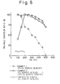
- the conversion ratio of both of NO x and NH 3 was measured at the outlet of the exhaust gas purifying catalyst, at various temperatures of the inflowing gas:
- Fig. 6 shows that the conversion ratio of NO x and NH 3 is maintained above 80%: when the inflowing gas temperature is within the range of about 100 to 180°C, with the example 1; when the inflowing gas temperature is within the range of about 100 to 470°C, with the example 2; and when the inflowing gas temperature is within the range of about 160 to 450°C, with the comparative example. Further, Fig.
- the conversion ratio of NO x and NH 3 is maintained above 90%: when the inflowing gas temperature is within the range of about 100 to 160°C, with the example 1; when the inflowing gas temperature is within the range of about 100 to 400°C, with the example 2; and when the inflowing gas temperature is within the range of about 180 to 350°C, with the comparative example. Accordingly, it can be found that, when the inflowing gas temperature is low, the exhaust gas catalyst of the example 1 reduces the amounts of NO x and NH 3 simultaneously more sufficient than the comparative example. Additionally, the exhaust gas catalyst of the example 2 reduces the amounts of NO x and NH 3 simultaneously more sufficient than the comparative example, over the wider range of the inflowing gas temperature.
- a model gas simulating the exhaust gas having the following composition was prepared and contacted to the exhaust gas purifying catalysts of the examples 1 and 2 and the comparative example, respectively.
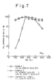
- the conversion ratio of NH 3 was measured at the outlet of the exhaust gas purifying catalyst, at various temperature of the inflowing gas:
- Fig. 7 shows that the conversion ratio of NH 3 is maintained above 80%: when the inflowing gas temperature is within the range of about 100 to 500°C, with the example 1; when the inflowing gas temperature is within the range of about 100 to 500°C, with the example 2; and when the inflowing gas temperature is within the range of about 220 to 450°C, with the comparative example. Further, Fig.
- the exhaust gas purifying catalyst comprises a first catalyst having zeolite carrying platinum and copper thereon.
- the exhaust gas purifying catalyst further comprises a second catalyst having zeolite carrying copper thereon.
- the second catalyst is arranged upstream of the first catalyst, with respect to the exhaust gas flow.
Landscapes
- Engineering & Computer Science (AREA)
- Chemical & Material Sciences (AREA)
- Combustion & Propulsion (AREA)
- General Engineering & Computer Science (AREA)
- Mechanical Engineering (AREA)
- Chemical Kinetics & Catalysis (AREA)
- Health & Medical Sciences (AREA)
- Materials Engineering (AREA)
- Toxicology (AREA)
- Biomedical Technology (AREA)
- Environmental & Geological Engineering (AREA)
- Analytical Chemistry (AREA)
- General Chemical & Material Sciences (AREA)
- Oil, Petroleum & Natural Gas (AREA)
- Exhaust Gas Treatment By Means Of Catalyst (AREA)
- Catalysts (AREA)
Claims (10)
- Procédé d'épuration des gaz d'échappement d'un moteur à combustion interne, comprenant les étapes consistant à :fournir un catalyseur d'épuration des gaz d'échappement comprenant un premier catalyseur ayant de la zéolite supportant du platine et du cuivre sur celui-ci,introduire les gaz d'échappement incluant l'oxyde d'azote et le gaz ammoniac dans ledit premier catalyseur à l'atmosphère d'oxydation ; etenlever simultanément desdits gaz d'échappement l'oxyde d'azote et le gaz ammoniac dans une atmosphère d'oxydation.
- Procédé selon la revendication 1, comprenant en outre la fourniture d'un second catalyseur ayant de la zéolite supportant du cuivre sur celui-ci.
- Procédé selon la revendication 2, dans lequel les premier et second catalyseurs sont disposés en série le long de la direction d'écoulement des gaz d'échappement.
- Procédé selon la revendication 3, dans lequel le premier catalyseur est disposé en aval du second catalyseur le long de la direction d'écoulement des gaz d'échappement.
- Procédé selon la revendication 3, dans lequel les premier et second catalyseurs sont supportés sur un substrat commun.
- Procédé selon la revendication 2, dans lequel les premier et second catalyseurs sont supportés sur un substrat commun.
- Procédé selon la revendication 6, dans lequel les premier et second catalyseurs sont disposés l'un sur l'autre pour former un catalyseur stratifié.
- Procédé selon la revendication 7, dans lequel le premier catalyseur est supporté sur le substrat et le second catalyseur est disposé sur le premier catalyseur.
- Procédé selon la revendication 2, dans lequel chacun des premier et second catalyseurs est supporté sur un substrat individuel.
- Procédé selon la revendication 1 ou 2, dans lequel ladite zéolite est une zéolite riche en dioxyde de silicium.
Applications Claiming Priority (9)
| Application Number | Priority Date | Filing Date | Title |
|---|---|---|---|
| JP29125895 | 1995-11-09 | ||
| JP291258/95 | 1995-11-09 | ||
| JP29125895 | 1995-11-09 | ||
| JP30153095 | 1995-11-20 | ||
| JP301530/95 | 1995-11-20 | ||
| JP30153095 | 1995-11-20 | ||
| JP320299/95 | 1995-12-08 | ||
| JP32029995A JP3499350B2 (ja) | 1995-12-08 | 1995-12-08 | 内燃機関の排ガス浄化方法 |
| JP32029995 | 1995-12-08 |
Publications (2)
| Publication Number | Publication Date |
|---|---|
| EP0773057A1 EP0773057A1 (fr) | 1997-05-14 |
| EP0773057B1 true EP0773057B1 (fr) | 2002-08-28 |
Family
ID=27337639
Family Applications (1)
| Application Number | Title | Priority Date | Filing Date |
|---|---|---|---|
| EP96117850A Expired - Lifetime EP0773057B1 (fr) | 1995-11-09 | 1996-11-07 | Catalyseur pour la purification de gaz d'échappement |
Country Status (3)
| Country | Link |
|---|---|
| US (1) | US6133185A (fr) |
| EP (1) | EP0773057B1 (fr) |
| DE (1) | DE69623232T2 (fr) |
Cited By (1)
| Publication number | Priority date | Publication date | Assignee | Title |
|---|---|---|---|---|
| US11845067B2 (en) | 2007-02-27 | 2023-12-19 | Basf Corporation | Copper CHA zeolite catalysts |
Families Citing this family (45)
| Publication number | Priority date | Publication date | Assignee | Title |
|---|---|---|---|---|
| JP2000356125A (ja) * | 1999-06-14 | 2000-12-26 | Honda Motor Co Ltd | 内燃機関の排気ガス浄化装置 |
| JP4568991B2 (ja) * | 2000-02-23 | 2010-10-27 | マツダ株式会社 | エンジンの排気浄化装置および燃料噴射時期の設定方法 |
| JP3871501B2 (ja) * | 2000-08-07 | 2007-01-24 | 株式会社ノリタケカンパニーリミテド | ゼオライト膜とその製造方法と膜リアクター |
| JP2002263501A (ja) * | 2001-03-05 | 2002-09-17 | Toyota Motor Corp | 一酸化炭素選択酸化触媒およびその製造方法 |
| GB2376903A (en) * | 2001-04-05 | 2002-12-31 | Johnson Matthey Plc | Nitrogen oxides emission control under lean-burn conditions |
| US7552583B2 (en) * | 2004-11-08 | 2009-06-30 | Caterpillar Inc. | Exhaust purification with on-board ammonia production |
| US7332135B2 (en) * | 2002-10-22 | 2008-02-19 | Ford Global Technologies, Llc | Catalyst system for the reduction of NOx and NH3 emissions |
| JPWO2005018807A1 (ja) * | 2003-08-26 | 2006-10-19 | ズードケミー触媒株式会社 | アンモニア分解触媒および該触媒を用いたアンモニア分解方法 |
| DE10360955A1 (de) * | 2003-12-23 | 2005-07-21 | Umicore Ag & Co. Kg | Abgasreinigungsanlage und Verfahren zur Entfernung von Stickoxiden aus dem Abgas von Verbrennungsmotoren mit Hilfe von katalytisch erzeugtem Ammoniak |
| WO2005099873A1 (fr) * | 2004-04-16 | 2005-10-27 | Hte Aktiengesellschaft The High Throughput Experimentation Company | Procede pour eliminer des substances nocives presentes dans des gaz d'echappement de moteurs a combustion interne et catalyseur pour mettre en oeuvre ledit procede |
| DE102004058210A1 (de) * | 2004-12-02 | 2006-06-14 | Hte Ag The High Throughput Experimentation Company | Katalysator zur Entfernung von Schadstoffen aus Abgasen von Verbrennungsmotoren |
| US20070227143A1 (en) * | 2004-11-08 | 2007-10-04 | Robel Wade J | Exhaust purification with on-board ammonia production |
| JP4907860B2 (ja) * | 2004-11-11 | 2012-04-04 | 株式会社キャタラー | フィルタ触媒 |
| US20090060809A1 (en) * | 2005-03-30 | 2009-03-05 | Sued-Chemie Catalysts Japan, Inc. | Ammonia Decomposition Catalyst and Process for Decomposition of Ammonia Using the Catalyst |
| WO2007004774A1 (fr) * | 2005-07-06 | 2007-01-11 | Heesung Catalysts Corporation | Catalyseur d'oxydation de nh3 et appareil pour traiter une emission ou un residu de nh3 |
| KR100765413B1 (ko) * | 2005-07-06 | 2007-10-09 | 희성촉매 주식회사 | 암모니아 산화촉매 및 이를 이용한 슬립 암모니아 또는폐암모니아 처리장치 |
| US7811536B2 (en) * | 2005-07-21 | 2010-10-12 | University Of Delaware | Nitrogen oxides storage catalysts containing cobalt |
| US7371353B2 (en) * | 2005-08-31 | 2008-05-13 | Caterpillar Inc. | Exhaust purification with on-board ammonia production |
| US7485272B2 (en) * | 2005-11-30 | 2009-02-03 | Caterpillar Inc. | Multi-stage system for selective catalytic reduction |
| US7805929B2 (en) * | 2005-12-21 | 2010-10-05 | Caterpillar Inc | Selective catalytic reduction system |
| US20100166628A1 (en) | 2006-02-15 | 2010-07-01 | Nicola Soeger | Catalyst for reducing nitrogen-containing pollutants from the exhaust gases of diesel engines |
| US7490462B2 (en) * | 2006-02-21 | 2009-02-17 | Caterpillar Inc. | Turbocharged exhaust gas recirculation system |
| US20080022666A1 (en) * | 2006-07-31 | 2008-01-31 | Driscoll James J | Balanced partial two-stroke engine |
| MX2009009095A (es) | 2007-02-27 | 2009-09-14 | Basf Catalysts Llc | Catalizadores de zeolita cha de cobre. |
| JP5761917B2 (ja) * | 2007-02-27 | 2015-08-12 | ビーエーエスエフ コーポレーション | 選択的アンモニア酸化用の二官能性触媒 |
| BRPI0810133B1 (pt) | 2007-04-26 | 2023-01-17 | Johnson Matthey Public Limited Company | Método para converter óxidos de nitrogênio de um gás em nitrogênio, sistema de escapamento para um motor de combustão interna de queima pobre veicular, e, aparelho |
| US20090196812A1 (en) | 2008-01-31 | 2009-08-06 | Basf Catalysts Llc | Catalysts, Systems and Methods Utilizing Non-Zeolitic Metal-Containing Molecular Sieves Having the CHA Crystal Structure |
| DE102008010330A1 (de) * | 2008-02-21 | 2009-09-03 | Süd-Chemie AG | SCR-Katalysator mit Ammoniak-Speicherfunktion |
| WO2009141895A1 (fr) * | 2008-05-20 | 2009-11-26 | イビデン株式会社 | Appareil de purification de gaz d'échappement |
| US20100050604A1 (en) * | 2008-08-28 | 2010-03-04 | John William Hoard | SCR-LNT CATALYST COMBINATION FOR IMPROVED NOx CONTROL OF LEAN GASOLINE AND DIESEL ENGINES |
| US8225597B2 (en) * | 2008-09-30 | 2012-07-24 | Ford Global Technologies, Llc | System for reducing NOx in exhaust |
| US8343448B2 (en) * | 2008-09-30 | 2013-01-01 | Ford Global Technologies, Llc | System for reducing NOx in exhaust |
| US8524185B2 (en) * | 2008-11-03 | 2013-09-03 | Basf Corporation | Integrated SCR and AMOx catalyst systems |
| US10632423B2 (en) * | 2008-11-03 | 2020-04-28 | Basf Corporation | Bimetallic catalysts for selective ammonia oxidation |
| US10583424B2 (en) | 2008-11-06 | 2020-03-10 | Basf Corporation | Chabazite zeolite catalysts having low silica to alumina ratios |
| US8844274B2 (en) * | 2009-01-09 | 2014-09-30 | Ford Global Technologies, Llc | Compact diesel engine exhaust treatment system |
| US8062618B2 (en) * | 2009-04-17 | 2011-11-22 | Ford Global Technologies, Llc | Exhaust aftertreatment system and method of treating exhaust gas |
| US8293198B2 (en) | 2009-12-18 | 2012-10-23 | Basf Corporation | Process of direct copper exchange into Na+-form of chabazite molecular sieve, and catalysts, systems and methods |
| US8293199B2 (en) | 2009-12-18 | 2012-10-23 | Basf Corporation | Process for preparation of copper containing molecular sieves with the CHA structure, catalysts, systems and methods |
| US8293182B2 (en) | 2010-05-05 | 2012-10-23 | Basf Corporation | Integrated SCR and AMOx catalyst systems |
| US9441517B2 (en) * | 2010-09-02 | 2016-09-13 | Ford Global Technologies, Llc | Diesel engine exhaust treatment system |
| US8137648B2 (en) * | 2010-10-12 | 2012-03-20 | Ford Global Technologies, Llc | Diesel engine exhaust treatment system and method including a platinum group metal trapping device |
| US9517434B2 (en) | 2012-02-15 | 2016-12-13 | Toyota Jidosha Kabushika Kaisha | Catalyst system for exhaust gas purification utilizing base metals, and controlling method therefor |
| EP3310477A1 (fr) * | 2015-06-18 | 2018-04-25 | Johnson Matthey Public Limited Company | Catalyseur de rejet d'ammoniac à couche unique ou à double couche |
| US10500571B2 (en) | 2017-03-29 | 2019-12-10 | Johnson Matthey Public Limited Company | ASC with platinum group metal in multiple layers |
Family Cites Families (25)
| Publication number | Priority date | Publication date | Assignee | Title |
|---|---|---|---|---|
| GB1362202A (en) * | 1971-01-19 | 1974-07-30 | British Leyland Motor Corp | Exhaust systems for internal combustion engines |
| US3825654A (en) * | 1972-04-21 | 1974-07-23 | Gulf Research Development Co | Process for reducing the content of nitrogen oxides in the exhaust gases from internal combustion engines |
| US3953576A (en) * | 1974-02-13 | 1976-04-27 | Standard Oil Company | Maximizing conversion of nitrogen oxides in the treatment of combustion exhaust gases |
| US4393031A (en) * | 1979-02-22 | 1983-07-12 | Werner Henke | Process for efficiently removing oxides of nitrogen from exhaust gas |
| FR2450946A1 (fr) * | 1979-03-08 | 1980-10-03 | Peugeot | Dispositif d'epuration des gaz d'echappement d'un moteur a explosions |
| US4395875A (en) * | 1981-07-24 | 1983-08-02 | Texaco Inc. | Method for rejuvenating an exhaust gas filter for a diesel engine |
| JP2748686B2 (ja) * | 1990-11-16 | 1998-05-13 | トヨタ自動車株式会社 | 筒内直接噴射式火花点火機関 |
| AU645632B2 (en) * | 1990-12-06 | 1994-01-20 | Tosoh Corporation | Catalyst for purifying exhaust gas |
| US5410873A (en) * | 1991-06-03 | 1995-05-02 | Isuzu Motors Limited | Apparatus for diminishing nitrogen oxides |
| JP2967113B2 (ja) | 1991-06-12 | 1999-10-25 | 株式会社豊田中央研究所 | 排気浄化方法 |
| JP3086015B2 (ja) * | 1991-08-07 | 2000-09-11 | トヨタ自動車株式会社 | 排気ガス浄化用触媒 |
| JP2800499B2 (ja) * | 1991-09-18 | 1998-09-21 | 日産自動車株式会社 | 炭化水素吸着材 |
| JP3098083B2 (ja) * | 1991-12-26 | 2000-10-10 | マツダ株式会社 | 排気ガス浄化用触媒 |
| JPH05228342A (ja) * | 1992-02-20 | 1993-09-07 | Mazda Motor Corp | 排気ガス浄化装置 |
| JPH06190246A (ja) * | 1992-12-25 | 1994-07-12 | Idemitsu Kosan Co Ltd | 自動車排気浄化装置 |
| EP0621400B1 (fr) * | 1993-04-23 | 1999-03-31 | Daimler-Benz Aktiengesellschaft | Moteur à combustion interne à injection et à compression d'air avec un dispositif pout traiter les gaz d'échappement à fin de réduire les oxides azoté |
| JP3246086B2 (ja) * | 1993-06-11 | 2002-01-15 | トヨタ自動車株式会社 | 内燃機関の排気浄化装置 |
| JPH07232035A (ja) * | 1994-02-21 | 1995-09-05 | Toray Ind Inc | 窒素酸化物の浄化方法および浄化装置 |
| JP3427581B2 (ja) * | 1994-09-13 | 2003-07-22 | トヨタ自動車株式会社 | 内燃機関の排気浄化装置 |
| JP3440654B2 (ja) * | 1994-11-25 | 2003-08-25 | トヨタ自動車株式会社 | 排気浄化装置 |
| DE19510642C2 (de) * | 1994-12-02 | 1997-04-10 | Volkswagen Ag | Verfahren zur Reduzierung von Schadstoffen des Abgases einer mehrere Zylinder aufweisenden Brennkraftmaschine |
| US5783160A (en) * | 1995-01-27 | 1998-07-21 | Toyota Jidosha Kabushiki Kaisha | Method for purifying combustion exhaust gas |
| ES2144779T3 (es) * | 1995-11-09 | 2000-06-16 | Toyota Motor Co Ltd | Procedimiento y dispositivo que permite purificar los gases de escape de un motor. |
| JPH09133032A (ja) * | 1995-11-10 | 1997-05-20 | Toyota Motor Corp | 内燃機関の排気浄化装置 |
| JP3823275B2 (ja) * | 1996-06-10 | 2006-09-20 | 富士通株式会社 | 動画像符号化装置 |
-
1996
- 1996-11-06 US US08/744,814 patent/US6133185A/en not_active Expired - Lifetime
- 1996-11-07 DE DE69623232T patent/DE69623232T2/de not_active Expired - Lifetime
- 1996-11-07 EP EP96117850A patent/EP0773057B1/fr not_active Expired - Lifetime
Cited By (1)
| Publication number | Priority date | Publication date | Assignee | Title |
|---|---|---|---|---|
| US11845067B2 (en) | 2007-02-27 | 2023-12-19 | Basf Corporation | Copper CHA zeolite catalysts |
Also Published As
| Publication number | Publication date |
|---|---|
| EP0773057A1 (fr) | 1997-05-14 |
| DE69623232T2 (de) | 2003-04-30 |
| DE69623232D1 (de) | 2002-10-02 |
| US6133185A (en) | 2000-10-17 |
Similar Documents
| Publication | Publication Date | Title |
|---|---|---|
| EP0773057B1 (fr) | Catalyseur pour la purification de gaz d'échappement | |
| Matsumoto | DeNOx catalyst for automotive lean-burn engine | |
| JP4357742B2 (ja) | Nh3の適切な添加により排ガス中の窒素酸化物含有量を低減させる方法および装置 | |
| KR100212904B1 (ko) | 촉매 반응 장치 | |
| JP5875586B2 (ja) | ディーゼルエンジンの排ガスから窒素酸化物を除去するための触媒 | |
| US5543124A (en) | Process for reducing nitrogen oxides | |
| KR100186852B1 (ko) | 연소 배기 가스의 정제방법 | |
| EP0819462A3 (fr) | Installation de purification de gaz d'échappement d'un moteur à combustion interne comprenant des adsorbeurs pour les oxydes nitriques | |
| JP2967113B2 (ja) | 排気浄化方法 | |
| US20100166628A1 (en) | Catalyst for reducing nitrogen-containing pollutants from the exhaust gases of diesel engines | |
| CA2154500A1 (fr) | Methodes de denitration de gaz d'echappement | |
| EP0707883A2 (fr) | Catalyseur et méthode pour la purification de gaz d'échappement | |
| US6489259B2 (en) | Mixed zeolite NOx catalyst | |
| WO2005064130A1 (fr) | Dispositif et procede d'elimination d'oxydes d'azote des gaz d'echappement de moteurs a combustion interne a l'aide d'ammoniaque genere catalytiquement | |
| JP3499350B2 (ja) | 内燃機関の排ガス浄化方法 | |
| JPH0576771A (ja) | 排気ガス浄化用触媒装置 | |
| JPH06134258A (ja) | 脱硝方法及びその触媒体 | |
| JPH07171349A (ja) | 排気ガス浄化方法 | |
| JP2751562B2 (ja) | 内燃機関の触媒式排ガス浄化装置 | |
| JP3325604B2 (ja) | 排気ガス浄化用触媒 | |
| JPH11324663A (ja) | 排気ガス浄化用触媒 | |
| JPH09220440A (ja) | 排ガス浄化方法 | |
| JP2004074139A (ja) | 排ガス浄化触媒及び浄化方法 | |
| JPH07100335A (ja) | 窒素酸化物の除去方法 | |
| EP0464709B1 (fr) | Procédé pour nettoyer les gaz d'échappement des moteurs à combustion interne |
Legal Events
| Date | Code | Title | Description |
|---|---|---|---|
| PUAI | Public reference made under article 153(3) epc to a published international application that has entered the european phase |
Free format text: ORIGINAL CODE: 0009012 |
|
| 17P | Request for examination filed |
Effective date: 19961107 |
|
| AK | Designated contracting states |
Kind code of ref document: A1 Designated state(s): DE FR GB |
|
| 17Q | First examination report despatched |
Effective date: 20000711 |
|
| GRAG | Despatch of communication of intention to grant |
Free format text: ORIGINAL CODE: EPIDOS AGRA |
|
| GRAG | Despatch of communication of intention to grant |
Free format text: ORIGINAL CODE: EPIDOS AGRA |
|
| GRAH | Despatch of communication of intention to grant a patent |
Free format text: ORIGINAL CODE: EPIDOS IGRA |
|
| GRAH | Despatch of communication of intention to grant a patent |
Free format text: ORIGINAL CODE: EPIDOS IGRA |
|
| GRAA | (expected) grant |
Free format text: ORIGINAL CODE: 0009210 |
|
| AK | Designated contracting states |
Kind code of ref document: B1 Designated state(s): DE FR GB |
|
| REG | Reference to a national code |
Ref country code: GB Ref legal event code: FG4D |
|
| REF | Corresponds to: |
Ref document number: 69623232 Country of ref document: DE Date of ref document: 20021002 |
|
| ET | Fr: translation filed | ||
| PLBE | No opposition filed within time limit |
Free format text: ORIGINAL CODE: 0009261 |
|
| STAA | Information on the status of an ep patent application or granted ep patent |
Free format text: STATUS: NO OPPOSITION FILED WITHIN TIME LIMIT |
|
| 26N | No opposition filed |
Effective date: 20030530 |
|
| PGFP | Annual fee paid to national office [announced via postgrant information from national office to epo] |
Ref country code: DE Payment date: 20121031 Year of fee payment: 17 Ref country code: FR Payment date: 20121130 Year of fee payment: 17 |
|
| PGFP | Annual fee paid to national office [announced via postgrant information from national office to epo] |
Ref country code: GB Payment date: 20121107 Year of fee payment: 17 |
|
| REG | Reference to a national code |
Ref country code: GB Ref legal event code: 746 Effective date: 20130827 |
|
| REG | Reference to a national code |
Ref country code: DE Ref legal event code: R084 Ref document number: 69623232 Country of ref document: DE Effective date: 20130829 |
|
| GBPC | Gb: european patent ceased through non-payment of renewal fee |
Effective date: 20131107 |
|
| REG | Reference to a national code |
Ref country code: FR Ref legal event code: ST Effective date: 20140731 |
|
| PG25 | Lapsed in a contracting state [announced via postgrant information from national office to epo] |
Ref country code: DE Free format text: LAPSE BECAUSE OF NON-PAYMENT OF DUE FEES Effective date: 20140603 |
|
| REG | Reference to a national code |
Ref country code: DE Ref legal event code: R119 Ref document number: 69623232 Country of ref document: DE Effective date: 20140603 |
|
| PG25 | Lapsed in a contracting state [announced via postgrant information from national office to epo] |
Ref country code: GB Free format text: LAPSE BECAUSE OF NON-PAYMENT OF DUE FEES Effective date: 20131107 Ref country code: FR Free format text: LAPSE BECAUSE OF NON-PAYMENT OF DUE FEES Effective date: 20131202 |