EP0773385A2 - Nass-Reibungs-Verbindungs-Vorrichtung - Google Patents
Nass-Reibungs-Verbindungs-Vorrichtung Download PDFInfo
- Publication number
- EP0773385A2 EP0773385A2 EP96117983A EP96117983A EP0773385A2 EP 0773385 A2 EP0773385 A2 EP 0773385A2 EP 96117983 A EP96117983 A EP 96117983A EP 96117983 A EP96117983 A EP 96117983A EP 0773385 A2 EP0773385 A2 EP 0773385A2
- Authority
- EP
- European Patent Office
- Prior art keywords
- hydraulic fluid
- wet type
- frictional engagement
- engagement device
- friction
- Prior art date
- Legal status (The legal status is an assumption and is not a legal conclusion. Google has not performed a legal analysis and makes no representation as to the accuracy of the status listed.)
- Granted
Links
- 239000012530 fluid Substances 0.000 claims abstract description 90
- 230000005540 biological transmission Effects 0.000 claims abstract description 10
- 230000002708 enhancing effect Effects 0.000 claims 1
- 238000010276 construction Methods 0.000 description 12
- 238000010586 diagram Methods 0.000 description 4
- 238000005461 lubrication Methods 0.000 description 3
- 230000003247 decreasing effect Effects 0.000 description 1
- 230000001050 lubricating effect Effects 0.000 description 1
- 238000010008 shearing Methods 0.000 description 1
- 238000011144 upstream manufacturing Methods 0.000 description 1
- 238000003466 welding Methods 0.000 description 1
Images


Classifications
-
- F—MECHANICAL ENGINEERING; LIGHTING; HEATING; WEAPONS; BLASTING
- F16—ENGINEERING ELEMENTS AND UNITS; GENERAL MEASURES FOR PRODUCING AND MAINTAINING EFFECTIVE FUNCTIONING OF MACHINES OR INSTALLATIONS; THERMAL INSULATION IN GENERAL
- F16D—COUPLINGS FOR TRANSMITTING ROTATION; CLUTCHES; BRAKES
- F16D39/00—Combinations of couplings according to two or more of the groups F16D31/00 - F16D37/00
-
- F—MECHANICAL ENGINEERING; LIGHTING; HEATING; WEAPONS; BLASTING
- F16—ENGINEERING ELEMENTS AND UNITS; GENERAL MEASURES FOR PRODUCING AND MAINTAINING EFFECTIVE FUNCTIONING OF MACHINES OR INSTALLATIONS; THERMAL INSULATION IN GENERAL
- F16D—COUPLINGS FOR TRANSMITTING ROTATION; CLUTCHES; BRAKES
- F16D35/00—Fluid clutches in which the clutching is predominantly obtained by fluid adhesion
Definitions
- the present invention relates to a wet type frictional engagement device.
- a lockup clutch of a torque converter and a clutch or a brake to engage, disengage or lock a component of an automatic transmission are known.
- An object of the present invention is to provide a wet type frictional engagement device in which the thickness of a film of oil formed between the friction plates can be most appropriately controlled and no judder is caused even in a semi-engagement state.
- a wet type frictional engagement device comprising: a first member connected to a power generating means; a second member arranged on the same axis as that of the first member, rotatable relative to the first member; a pair of friction plates respectively connected to the above two members, arranged so that the pair of friction plates can be frictionally engaged with each other; a pushing means for pushing at least one of the pair of friction plates against the other so that the pair of friction plates can be frictionally engaged with each other; and a hydraulic fluid feed means for feeding hydraulic fluid between the pair of friction plates frictionally engaged with each other by the pushing means, so as to change the distance between the pair of friction plates and thereby control transmission of power.
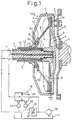
- Reference numeral 100 denotes an overall arrangement of the first embodiment of the wet type frictional engagement device of the present invention.
- This wet type frictional engagement device is used for an automobile. Therefore, this wet type frictional engagement device is arranged between an engine (not shown) disposed in the right portion of the drawing and a transmission (not shown) disposed in the left portion of the drawing. Therefore, the right is defined as a front side, and the left is defined as a rear side in this specification, hereinafter.
- Reference numeral 1 is a shell member, which is composed of a front cover 2 and a rear cover 3 which are connected by means of welding.
- the front cover 2 is connected to an input shaft 4 via an input plate 5.
- the input shaft 4 is connected to a crank shaft of the engine (not shown) in a portion not shown in the drawing.
- Reference numeral 6 is a clutch disk, and the circumferential end portion on the inner diameter side is connected to an output shaft 7 by means of a spline connection.
- a friction member 6a is attached onto the outer circumferential side of the clutch disk 6 which faces the front cover 2.
- Reference numeral 8 is a diaphragm type spring. As shown in the drawing, the outer circumferential side of the diaphragm type spring 8 extends to the front side and comes into contact with the clutch disk 6, and the inner circumferential side of the diaphragm type spring 8 extends to the rear side and comes into contact with the disk portion 10 formed integrally with the outer race 9a of the bearing 9. In this connection, it is possible to form the disk portion 10 separately from the outer race 9a of the bearing 9.
- the inner race 9b of the bearing 9 is connected to the rear cover 3 of the shell member 1.
- the clutch disk 6 is pushed by the spring 8 toward the front cover 2 at all times.
- hydraulic fluid is fed into the hydraulic fluid chamber A formed between the clutch disk 6 and the front cover 2.
- first hydraulic fluid passage 11 at a center of the output shaft 7
- second hydraulic fluid passage 13 between the output shaft 7 and the intermediate shaft 12 arranged outside the output shaft 7.
- the hydraulic pump 16 sucks the hydraulic fluid that has returned into the oil pan 17, and feeds the hydraulic fluid into the hydraulic fluid passage 11.
- a flow meter 18 In the middle of the hydraulic fluid passage 11, there is provided a flow meter 18.
- a variable aperture 19 is adjusted so that a flow rate measured by the flow meter 18 can be an appropriate value to obtain a predetermined engaging condition.
- the flow meter 18 is a differential type flow meter, at the center of which an orifice 18 is arranged, and there are provided a pressure gauge 30 to detect the pressure Pu in the upstream of the flow meter and a pressure gauge 31 to detect the pressure Pd in the downstream. Pressure signals detected by the pressure gauges 30, 31 are respectively sent to the variable aperture 19.
- the flow rate Q may be increased so that a sufficiently large quantity of hydraulic fluid can be made to flow, and the clearance "h" may be increased so that the transmission torque T can be reduced.
- a quantity of hydraulic fluid is sufficiently large, so that fluid lubrication can be conducted on the friction surface and generated heat can be quickly removed. Therefore, it is possible to avoid the occurrence of a high temperature portion on the friction surface.
- the surface pressure PD on the disk is expressed by the following expression.
- PD (FK - FP)/ ⁇ ( ⁇ /4) ⁇ (D2 2 - D1 2 ) ⁇ where D1 is an inner diameter of the frictional member and D2 is an outer diameter of the frictional member.
- Fig. 4 is a view showing the construction of the second embodiment of the present invention.
- a piston 20 capable of moving in the axial direction.
- the clutch disk 6 is pushed toward the front cover 2 by the action of the spring 8 via the piston 20.
- Friction members 6a are attached onto both sides of the clutch disk 6, and a hole 6b is formed on the inner diameter side of the clutch disk 6.
- an area of the friction surface of the friction member of the second embodiment can be increased to twice as large as that of the friction surface of the first embodiment described before. Further, it is possible to double the heat capacity of the friction members.
- ⁇ PAB is a pressure difference between the hydraulic pressure PA in the hydraulic pressure chamber A and the hydraulic pressure PB in the hydraulic pressure chamber B.
- the variable aperture 19 is adjusted so that a predetermined intensity of torque can be obtained. Therefore, the pressure gauge 40 is attached to the hydraulic fluid passage 11 communicated with the hydraulic fluid chamber A, and the pressure gauge 50 is attached to the hydraulic fluid passage 13 communicated with the hydraulic fluid chamber B.
- reference numeral 21 is a changeover valve to change over the hydraulic fluid passage.
- the changeover valve 21 When the changeover valve 21 is set at a position "a", in the same manner as that of the first embodiment, hydraulic fluid flows from the hydraulic fluid passage 11 into the hydraulic fluid chambers A and A'. Then it flows into the hydraulic fluid chamber B via the clearance 20a formed on the outer circumference of the piston 20. Accordingly, in the same manner as that of the first embodiment, it is possible to engage and disengage the clutch, and it is also possible to provide a state of semi-engagement of the clutch.
- the changeover valve 21 When the changeover valve 21 is set at a position "b", hydraulic fluid flows from the hydraulic fluid passage 13 into the hydraulic fluid chamber B.
- the clearance formed on one friction surface is defined as h1
- the clearance formed on the other friction surface is defined as h2. Since the hole 6b is formed on the inner diameter side of the clutch disk 6, in the case of h1 ⁇ h2, the hydraulic pressure Ph1 on the h1 side becomes higher than the hydraulic pressure Ph2 on the h2 side. That is, Ph1 > Ph2. As a result, there is a tendency that h1 is increased. Accordingly, h1 and h2 automatically satisfy the expression h1 ⁇ h2 .
- Fig. 6 is a view showing a construction of the third embodiment.
- the clutch disk 6 is not frictionally engaged with the front cover 2 by a spring force but frictionally engaged with the front cover 2 by hydraulic pressure.
- the outer sleeve 15 is welded to the inner shell 22, and there is provided a piston 23 capable of sliding on an inner surface of the annular cylinder portion formed by the inner shell 22 and the outer sleeve 15.
- a hydraulic fluid chamber C is defined by the inner shell 22, piston 23 and outer sleeve 15.
- This hydraulic fluid chamber C is communicated with the hydraulic fluid passage 13 via the hole 15a in the same manner as that of the second embodiment. Due to the above construction, hydraulic fluid is fed from the hydraulic fluid pump 16 to the hydraulic fluid chamber C via the hydraulic fluid passage 13.
- an outlet of the hydraulic pressure pump 16 forks off into two branches and also communicates with the hydraulic fluid passage 13.
- a variable aperture 19' is added to the hydraulic circuit.
- hydraulic fluid is fed from the hydraulic fluid passage 11 into the hydraulic fluid chamber A.
- This hydraulic fluid flows in a clearance formed between the outer circumferential portion of the inner shell 22 and the shell member 1. Then it flows into the hydraulic fluid chamber D formed between the shell member 1 and the inner shell 22. Further, the hydraulic fluid flows into the hole 15b formed in the outer sleeve 15 and passes in the hydraulic fluid passage 24 formed between the outer sleeve 15 and the intermediate shaft 12 and discharges toward the oil pan 17.
- the clearance "h” formed between the clutch disk 6 and the front cover 2 is changed by the hydraulic pressure PC in the hydraulic pressure chamber C even if the difference ⁇ PAD between the hydraulic pressure PA in the hydraulic pressure chamber A and the hydraulic pressure PD in the hydraulic pressure chamber D is kept constant. That is, the clearance "h” is changed as shown in Fig. 7.
- Fig. 8 is a view showing a construction of the fourth embodiment.
- the clutch disk 6 is engaged with the front cover 2 by the above force.
- a quantity of hydraulic fluid fed into the hydraulic fluid chamber A is adjusted as follows. A difference between the pressure in the hydraulic fluid passage 11 communicated with the hydraulic fluid chamber A and the pressure in the hydraulic fluid passage 13 communicated with the hydraulic fluid chamber E is measured, and the thickness of a film of oil is controlled in accordance with the pressure difference, that is, the variable aperture 19 is adjusted. Consequently, in the same manner as that of the second and the third embodiment, the pressure gauges 40, 50 are arranged in this embodiment.
- variable aperture 19 is incorporated into this hydraulic pressure circuit in series. Therefore, the flow rate can be directly controlled.
- the same changeover valve 21 as that used in the second embodiment is used. Therefore, when the changeover valve is set in the state "b", it is possible to provide a higher engaging force than that provided in the state "a".
- the fourth embodiment is characterized as follows. It is unnecessary to provide a piston. Further, the thrust F generated by the axial flow is changed in accordance with the engine speed. Therefore, when the engine speed is increased, the thrust is increased in accordance with the engine speed, and the transmission torque is also increased. In this way, the transmission torque is automatically adjusted.
- Fig. 9 is a view showing a variation of the fourth embodiment.
- an inner surface of the rear cover on the outer circumferential side and a rear surface of the clutch disk 6, which is a side of the clutch disk 6 to receive the axial flow of hydraulic fluid are formed to be circular.
- a labyrinth seal 26 is incorporated into a passage connecting a space between the clutch disk 6 and the front cover 2 with a space in which the axial flow of hydraulic fluid is generated. Further, a distance from the rotation center to a portion where the labyrinth seal 26 is connected to the space formed between the clutch disk 6 and the front cover 2 is made to be smaller than a distance from the rotation center to a portion where the labyrinth seal 26 is connected to the space where the axial flow of hydraulic fluid is generated.
- variable aperture 19 Since the variable aperture 19 is arranged on the delivery side, the inner pressure is not lowered, so that the occurrence of cavitation can be prevented.
- hydraulic fluid is fed onto friction surfaces of a pair of friction plates opposed to each other so that they can be engaged with, semi-engaged with and disengaged from each other. Therefore, since hydraulic fluid is provided between the friction plates even in a state of semi-engagement, it is possible to prevent the occurrence of judder of a clutch.
Landscapes
- Engineering & Computer Science (AREA)
- General Engineering & Computer Science (AREA)
- Mechanical Engineering (AREA)
- Hydraulic Clutches, Magnetic Clutches, Fluid Clutches, And Fluid Joints (AREA)
- Mechanical Operated Clutches (AREA)
Applications Claiming Priority (3)
| Application Number | Priority Date | Filing Date | Title |
|---|---|---|---|
| JP29305595 | 1995-11-10 | ||
| JP293055/95 | 1995-11-10 | ||
| JP7293055A JPH09133158A (ja) | 1995-11-10 | 1995-11-10 | 湿式摩擦係合装置 |
Publications (3)
| Publication Number | Publication Date |
|---|---|
| EP0773385A2 true EP0773385A2 (de) | 1997-05-14 |
| EP0773385A3 EP0773385A3 (de) | 1998-05-13 |
| EP0773385B1 EP0773385B1 (de) | 2001-10-10 |
Family
ID=17789895
Family Applications (1)
| Application Number | Title | Priority Date | Filing Date |
|---|---|---|---|
| EP96117983A Expired - Lifetime EP0773385B1 (de) | 1995-11-10 | 1996-11-08 | Nass-Reibungs-Verbindungs-Vorrichtung |
Country Status (4)
| Country | Link |
|---|---|
| US (1) | US5871073A (de) |
| EP (1) | EP0773385B1 (de) |
| JP (1) | JPH09133158A (de) |
| DE (1) | DE69615782T2 (de) |
Cited By (1)
| Publication number | Priority date | Publication date | Assignee | Title |
|---|---|---|---|---|
| DE10161205A1 (de) * | 2001-12-13 | 2003-06-26 | Daimler Chrysler Ag | Kraftfahrzeugantriebsstrang mit einer geschlossenen Kupplungsglocke |
Families Citing this family (7)
| Publication number | Priority date | Publication date | Assignee | Title |
|---|---|---|---|---|
| JP2002013549A (ja) * | 2000-06-29 | 2002-01-18 | Tochigi Fuji Ind Co Ltd | カップリング及び発進クラッチ |
| JP2009036249A (ja) | 2007-07-31 | 2009-02-19 | Jtekt Corp | 湿式摩擦板 |
| JP4859817B2 (ja) * | 2007-11-30 | 2012-01-25 | ヴァレオユニシアトランスミッション株式会社 | 捩り振動低減装置 |
| DE102014213626A1 (de) * | 2014-07-14 | 2016-01-14 | Zf Friedrichshafen Ag | Anfahrelement, Getriebe und Antriebsstrang mit dem Anfahrelement |
| CN104819219A (zh) * | 2015-04-23 | 2015-08-05 | 青岛丰宝汽车离合器有限公司 | 湿式离合器总成 |
| JP2023020471A (ja) * | 2021-07-30 | 2023-02-09 | 株式会社デンソー | クラッチアクチュエータ |
| CN114941569B (zh) * | 2022-05-27 | 2023-12-05 | 上海三一重机股份有限公司 | 动力系统及工程机械 |
Family Cites Families (18)
| Publication number | Priority date | Publication date | Assignee | Title |
|---|---|---|---|---|
| US2442840A (en) * | 1942-07-09 | 1948-06-08 | Borg Warner | Torque converter with friction clutch |
| DE896009C (de) * | 1949-06-10 | 1953-11-09 | Hans Ferdinand Toennies | Drehzahlwandler zwischen antreibender und angetriebener Welle, insbesondere fuer Kraftfahrzeuge oder andere Maschinenantriebe |
| US2920728A (en) * | 1956-07-12 | 1960-01-12 | Daimler Benz Ag | Transmission, particularly for automotive purposes |
| US3011607A (en) * | 1958-02-17 | 1961-12-05 | Schwitzer Corp | Fluid coupling for accessory drive |
| US3209874A (en) * | 1962-11-09 | 1965-10-05 | Socony Mobil Oil Co | Fluid-mechanical power transmission system |
| US3236346A (en) * | 1963-05-15 | 1966-02-22 | Eaton Mfg Co | Shear type fluid coupling |
| FR1465378A (fr) * | 1965-02-11 | 1967-01-13 | Ferodo Sa | Transmission, notamment pour véhicules automobiles |
| JPS5132785B2 (de) * | 1972-07-26 | 1976-09-14 | ||
| FR2356052A1 (fr) * | 1976-06-25 | 1978-01-20 | Ferodo Sa | Transmission a accouplement hydrocinetique debrayable, notamment pour vehicule automobile |
| US4091899A (en) * | 1977-04-18 | 1978-05-30 | General Motors Corporation | Lock-up converter clutch with centrifugal control valves |
| JPS5934905B2 (ja) * | 1978-09-13 | 1984-08-25 | 日産自動車株式会社 | ロツクアツプ装置付トルクコンバ−タ |
| JPS604628A (ja) * | 1983-06-23 | 1985-01-11 | Daikin Mfg Co Ltd | 薄肉型ダンパ−デイスク |
| JPS60211160A (ja) * | 1984-04-04 | 1985-10-23 | Nissan Motor Co Ltd | トルクコンバ−タのスリツプ制御装置 |
| US4986398A (en) * | 1989-03-27 | 1991-01-22 | Luk Lamellen Und Kupplungsbau Gmbh | Torque converter clutch |
| JP2843609B2 (ja) * | 1989-09-09 | 1999-01-06 | ジャトコ株式会社 | ロックアップクラッチの作動制御装置 |
| EP0452887B1 (de) * | 1990-04-18 | 1995-08-16 | Mazda Motor Corporation | Steuerungssystem für ein Momentwandler |
| JP2557778Y2 (ja) * | 1992-09-07 | 1997-12-17 | 株式会社エクセディ | トルクコンバータ用ロックアップ装置 |
| JP3214208B2 (ja) * | 1993-04-13 | 2001-10-02 | トヨタ自動車株式会社 | 湿式クラッチ |
-
1995
- 1995-11-10 JP JP7293055A patent/JPH09133158A/ja active Pending
-
1996
- 1996-11-08 EP EP96117983A patent/EP0773385B1/de not_active Expired - Lifetime
- 1996-11-08 DE DE69615782T patent/DE69615782T2/de not_active Expired - Fee Related
- 1996-11-08 US US08/745,922 patent/US5871073A/en not_active Expired - Fee Related
Non-Patent Citations (1)
| Title |
|---|
| None |
Cited By (1)
| Publication number | Priority date | Publication date | Assignee | Title |
|---|---|---|---|---|
| DE10161205A1 (de) * | 2001-12-13 | 2003-06-26 | Daimler Chrysler Ag | Kraftfahrzeugantriebsstrang mit einer geschlossenen Kupplungsglocke |
Also Published As
| Publication number | Publication date |
|---|---|
| EP0773385B1 (de) | 2001-10-10 |
| JPH09133158A (ja) | 1997-05-20 |
| US5871073A (en) | 1999-02-16 |
| DE69615782T2 (de) | 2002-05-29 |
| DE69615782D1 (de) | 2001-11-15 |
| EP0773385A3 (de) | 1998-05-13 |
Similar Documents
| Publication | Publication Date | Title |
|---|---|---|
| US6296019B1 (en) | Pressure medium system | |
| US6375233B1 (en) | Transmission | |
| US4261213A (en) | Friction transmission | |
| KR100353261B1 (ko) | 클러치배열 | |
| US7815026B2 (en) | Torque converter impeller clutch control | |
| US4466311A (en) | Slip control system for a clutch | |
| US4403975A (en) | Cone-pulley belt-type transmission | |
| US5935036A (en) | Method and device for controlling a coupling | |
| US7128688B2 (en) | Hydraulic control for automatic transmission | |
| US4762213A (en) | Driving system for a four-wheel drive vehicle | |
| US4091899A (en) | Lock-up converter clutch with centrifugal control valves | |
| US20090139818A1 (en) | Torque converter | |
| US6142280A (en) | Oil pressure circuit in a starting clutch | |
| US5871073A (en) | Wet type frictional engagement device | |
| US3862676A (en) | Clutch controlled by engine speed and torque | |
| US4905812A (en) | Apparatus for cooling a clutch assembly with a hydraulic fluid | |
| US4371066A (en) | Wet multiple disc clutch device for a vehicle transmission | |
| US4448293A (en) | Pressure-responsive control for a power train of the type having a torque converter equipped with a lockup clutch | |
| JPH10511172A (ja) | シフトショックを阻止できる流体操作摩擦クラッチ及びその使用方法 | |
| US4520912A (en) | Hydraulically actuated starting clutch assembly | |
| EP0435559B1 (de) | Hydraulische Steuerung für ein stufenloses Fahrzeuggetriebe mit zwei je nach Schalthebel Position aktivierbaren Schaltventilen | |
| US6419067B1 (en) | Pressure-medium-actuated clutch | |
| JP2827727B2 (ja) | 無段変速機の油圧制御装置 | |
| US3926288A (en) | Centrifugal clutch with overspeed relief valve | |
| EP0435558A2 (de) | Hydraulisches Steuergerät für ein stufenloses Getriebe mit einem von der Fahrgeschwindigkeit abhängig arbeitenden Schaltventil |
Legal Events
| Date | Code | Title | Description |
|---|---|---|---|
| PUAI | Public reference made under article 153(3) epc to a published international application that has entered the european phase |
Free format text: ORIGINAL CODE: 0009012 |
|
| 17P | Request for examination filed |
Effective date: 19961108 |
|
| AK | Designated contracting states |
Kind code of ref document: A2 Designated state(s): DE FR GB |
|
| PUAL | Search report despatched |
Free format text: ORIGINAL CODE: 0009013 |
|
| AK | Designated contracting states |
Kind code of ref document: A3 Designated state(s): DE FR GB |
|
| 17Q | First examination report despatched |
Effective date: 19990215 |
|
| GRAG | Despatch of communication of intention to grant |
Free format text: ORIGINAL CODE: EPIDOS AGRA |
|
| GRAG | Despatch of communication of intention to grant |
Free format text: ORIGINAL CODE: EPIDOS AGRA |
|
| GRAH | Despatch of communication of intention to grant a patent |
Free format text: ORIGINAL CODE: EPIDOS IGRA |
|
| GRAH | Despatch of communication of intention to grant a patent |
Free format text: ORIGINAL CODE: EPIDOS IGRA |
|
| GRAA | (expected) grant |
Free format text: ORIGINAL CODE: 0009210 |
|
| AK | Designated contracting states |
Kind code of ref document: B1 Designated state(s): DE FR GB |
|
| REF | Corresponds to: |
Ref document number: 69615782 Country of ref document: DE Date of ref document: 20011115 |
|
| ET | Fr: translation filed | ||
| REG | Reference to a national code |
Ref country code: GB Ref legal event code: IF02 |
|
| PLBE | No opposition filed within time limit |
Free format text: ORIGINAL CODE: 0009261 |
|
| STAA | Information on the status of an ep patent application or granted ep patent |
Free format text: STATUS: NO OPPOSITION FILED WITHIN TIME LIMIT |
|
| 26N | No opposition filed | ||
| PGFP | Annual fee paid to national office [announced via postgrant information from national office to epo] |
Ref country code: GB Payment date: 20031105 Year of fee payment: 8 |
|
| PGFP | Annual fee paid to national office [announced via postgrant information from national office to epo] |
Ref country code: FR Payment date: 20031110 Year of fee payment: 8 |
|
| PGFP | Annual fee paid to national office [announced via postgrant information from national office to epo] |
Ref country code: DE Payment date: 20031120 Year of fee payment: 8 |
|
| PG25 | Lapsed in a contracting state [announced via postgrant information from national office to epo] |
Ref country code: GB Free format text: LAPSE BECAUSE OF NON-PAYMENT OF DUE FEES Effective date: 20041108 |
|
| PG25 | Lapsed in a contracting state [announced via postgrant information from national office to epo] |
Ref country code: DE Free format text: LAPSE BECAUSE OF NON-PAYMENT OF DUE FEES Effective date: 20050601 |
|
| GBPC | Gb: european patent ceased through non-payment of renewal fee |
Effective date: 20041108 |
|
| PG25 | Lapsed in a contracting state [announced via postgrant information from national office to epo] |
Ref country code: FR Free format text: LAPSE BECAUSE OF NON-PAYMENT OF DUE FEES Effective date: 20050729 |
|
| REG | Reference to a national code |
Ref country code: FR Ref legal event code: ST |