EP0773413A2 - Luftströmungsrichtung-Steuergerät für Klimageräte - Google Patents
Luftströmungsrichtung-Steuergerät für Klimageräte Download PDFInfo
- Publication number
- EP0773413A2 EP0773413A2 EP97100233A EP97100233A EP0773413A2 EP 0773413 A2 EP0773413 A2 EP 0773413A2 EP 97100233 A EP97100233 A EP 97100233A EP 97100233 A EP97100233 A EP 97100233A EP 0773413 A2 EP0773413 A2 EP 0773413A2
- Authority
- EP
- European Patent Office
- Prior art keywords
- air
- vanes
- vane
- blow
- shaft
- Prior art date
- Legal status (The legal status is an assumption and is not a legal conclusion. Google has not performed a legal analysis and makes no representation as to the accuracy of the status listed.)
- Granted
Links
Images



Classifications
-
- F—MECHANICAL ENGINEERING; LIGHTING; HEATING; WEAPONS; BLASTING
- F24—HEATING; RANGES; VENTILATING
- F24F—AIR-CONDITIONING; AIR-HUMIDIFICATION; VENTILATION; USE OF AIR CURRENTS FOR SCREENING
- F24F13/00—Details common to, or for air-conditioning, air-humidification, ventilation or use of air currents for screening
- F24F13/02—Ducting arrangements
- F24F13/06—Outlets for directing or distributing air into rooms or spaces, e.g. ceiling air diffuser
- F24F13/075—Outlets for directing or distributing air into rooms or spaces, e.g. ceiling air diffuser having parallel rods or lamellae directing the outflow, e.g. the rods or lamellae being individually adjustable
-
- F—MECHANICAL ENGINEERING; LIGHTING; HEATING; WEAPONS; BLASTING
- F16—ENGINEERING ELEMENTS AND UNITS; GENERAL MEASURES FOR PRODUCING AND MAINTAINING EFFECTIVE FUNCTIONING OF MACHINES OR INSTALLATIONS; THERMAL INSULATION IN GENERAL
- F16K—VALVES; TAPS; COCKS; ACTUATING-FLOATS; DEVICES FOR VENTING OR AERATING
- F16K1/00—Lift valves or globe valves, i.e. cut-off apparatus with closure members having at least a component of their opening and closing motion perpendicular to the closing faces
- F16K1/16—Lift valves or globe valves, i.e. cut-off apparatus with closure members having at least a component of their opening and closing motion perpendicular to the closing faces with pivoted closure-members
- F16K1/165—Lift valves or globe valves, i.e. cut-off apparatus with closure members having at least a component of their opening and closing motion perpendicular to the closing faces with pivoted closure-members with a plurality of closure members
-
- F—MECHANICAL ENGINEERING; LIGHTING; HEATING; WEAPONS; BLASTING
- F24—HEATING; RANGES; VENTILATING
- F24F—AIR-CONDITIONING; AIR-HUMIDIFICATION; VENTILATION; USE OF AIR CURRENTS FOR SCREENING
- F24F1/00—Room units for air-conditioning, e.g. separate or self-contained units or units receiving primary air from a central station
Definitions
- the present invention relates to an air-direction adjusting apparatus in an air-conditioning equipment, which is disposed at a blow-outlet thereof.
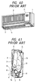
- Figs. 60 to 62 are views showing an air-direction adjusting apparatus in a conventional air-conditioning equipment as disclosed in Japanese Utility Model Unexamined Publication No. Sho-58-69735.
- Fig. 60 is a perspective view of a body of the air-conditioning equipment;
- Fig. 61 is a cross section of Fig. 60; and
- Fig. 62 is a vertical section of Fig. 60.
- the reference numeral 1 represents a body of an air-conditioning equipment; 2, a front panel having a suction inlet 3 and for covering the front surface of the body 1; 4, a blow-outlet having an opening at a front lower portion of the body 1; 5, a heat exchanger disposed so as to face the suction inlet 3; 6, a casing provided in the inside of the body 1 and for forming an air course 13; 7, a change vane provided at the blow-outlet 4 so as to be pivotally mounted to left and right side walls 11 and 15 of the front panel 2 by a shaft 16 mounted to left and right end portions of the blow-outlet 4 and for changing the air direction to the horizontal direction, the perpendicularly falling direction or an oblique direction; 8, a plurality of parallel guide vanes provided between walls 10 and 14 at left and right side portions of a blow-out nozzle 9 so as to be pivotally held by a pivotal shaft 17 and for changing the air direction to the left-rightwise direction; 9, a blow-out nozzle
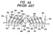
- Figs. 65 and 66 are views showing another air-direction adjusting apparatus in a conventional air-conditioning equipment as disclosed in Japanese Utility Model Unexamined Publication No. Sho-63-147650.
- Fig. 65 is a cross section of the apparatus; and
- Fig. 66 is a view for explaining the operating state of the apparatus depicted in Fig. 65.
- the reference numeral 201 represents a blow-outlet; 202, an inner wall of the blow-outlet 201; and 203, a plurality of vanes disposed at substantially equal intervals and for changing the air direction.
- the plurality of vanes 203 are divided into two groups and the respective groups each of which is composed of a plurality of vanes are provided in the left and right respectively in Fig. 65.
- the reference numeral 204 represents shafts which are disposed for the vanes 203 respectively so as to be erected from the inner wall 202 and for pivotally holding the one-end side of an edge portion at one side of each of the vanes 203.
- connection arms 205 each of which connects a group of vanes 203 and is provided with connection shafts 206 for pivotally holding the other-end side of the edge portion where the respective shafts 204 of the vanes 203 are disposed.
- connection shafts 206 are arranged in a line inclined with respect to a line connecting the respective shafts 204 of the vanes 203 so that the distance between the shaft 204 of the inner vane 203 and the connection shaft 206 in Fig. 65 is set to be shorter than the distance between the shaft 204 of the outer vane 203 and the connection shaft 206 in Fig. 65.
- the other air-direction adjusting apparatus in the conventional air-conditioning equipment shown in Figs. 65 and 66 is configured as described above.
- An object of the present invention is to provide an air-direction adjusting apparatus in an air-conditioning equipment in which not only the vanes make the rotating operations smoothly but noise at the vane portions is reduced.
- the invention provides an air-direction adjusting apparatus in an air-conditioning equipment, which comprises guide vanes which are disposed in a blow-outlet and which make rotational movement to thereby change the air direction, characterised in that each vane has a C-shaped annular pivotal bearing and a sleeve fitted into the bearing so as to be held by the bearing, a shaft extending from an inner wall of the blow-outlet being inserted into the sleeve, the shaft having claws which project from the upper end portion of the shaft so as to retain the sleeve.
- the air-direction adjusting apparatus in an air-conditioning equipment in one embodiment is provided with: vanes disposed at a blow-outlet and making rotational movement to thereby change the air direction; pivotal bearings each of which is provided in an edge portion on one side of each of the vanes to form a C-shape which is such that an annular side thereof is cut-off; sleeves fitted to the pivotal bearings so as to be held by the pivotal bearings respectively; and shafts provided so as to erected from an inner wall of the blow-outlet and inserted into the sleeves respectively, the shafts being provided with claws which are provided at upper ends of the shafts so as to project from the shafts and are engaged with upper edges of the sleeves, respectively.
- the vanes disposed at a blow-outlet are pivoted on the shafts erected from the inner wall of the blow-outlet through the sleeves and the pivotal bearings.
- the reference numeral 201 represents a blow-outlet; 202, an inner wall of the blow-outlet 201; 231, a first-kind vane disposed to be near the inner wall 201 which is one side of the blow-outlet 1; and 210, a C-shaped pivotal bearing shaped obtained by cutting one side of a ring and provided in the vicinity of one end of an edge portion on one side of the first-kind vane 231.
- the reference numeral 211 represents a rotational bearing provided on the other-end side of the edge portion in which the pivotal bearing 210 of the first-kind vane 231 is provided; and 232, a second-kind vane disposed so as to be opposite to the first-kind vane 231 among one group of vanes and formed in the same manner as the first-kind vane 231 so that the second-kind vane is provided with both a pivotal bearing 210 and a rotational bearing 211 but the two bearings are arranged at a shorter distance than the distance in the first-kind vane 231.
- the reference numeral 233 represents a plurality of third- kind vanes provided separately between the first-kind vane 231 and the second-kind vane 232.
- the third-kind vanes are formed in the same manner as the first-kind vane 231 and provided with pivotal bearings 210 provided in positions corresponding to the pivotal bearing 210 of the first-kind vane 231, each of the third-kind vanes being provided with an engagement portion 213 formed on the other-end side of an edge portion where the pivotal bearing 210 is disposed and having an elongated hole (slot) 212 along the length of the edge portion.
- the reference numeral 214 represents a connection arm disposed along end portions opposite to the pivotal bearings, of the first-, second- and third-kind vanes 231, 232 and 233.
- the connection arm has connection shafts 215 provided at its opposite end portions so as to be pivotally held by the rotational bearings 211 of the first- and second-kind vanes 231 and 232 respectively, and intermediate connection shafts 216 provided at its intermediate portion so as to be movably fitted into the elongated holes 212 of the engagement portions 213 of the third- kind vanes 233 respectively.
- the following operation is carried out in the case where two, left and right groups of vanes are disposed in the left and right respectively as shown in Fig. 66 so that the lower sides are far from each other in Fig. 66. That is, the respective end portions opposite to the pivotal bearings 210, of the first-, second- and third-kind vanes 231, 232 and 233 are engaged with the connection arm 214. Particularly the end portions of the third-kind vanes 233 are engaged with the connection arm 214 by the intermediate connection shafts 216 movably fitted into the elongated holes 212 of the engagement portions 213.
- first-, second- and third-kind vanes 231, 232 and 233 are moved respectively in accordance with the lengthwise movement of the connection arm 214 so as to be disposed in inclined posture in the same manner as in the case of Fig. 66.
- the third-kind vanes 233 are produced while the distances between the pivotal bearings 210 and the engagement portions 213 are successively changed in accordance with the positions of the arrangement of the third- kind vanes 233. Accordingly, the third-kind vanes 233 can be produced easily, so that the air-direction adjusting apparatus in the air-conditioning equipment can be assembled up by simple work.
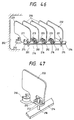
- Figs. 48 and 49 are views showing another embodiment
- Fig. 48 is a cross-sectional plan view of a blow-outlet; and Fig. 49 is an enlarged perspective view of important part of Fig. 48.
- the other structure in Figs. 48 and 49 is the same as that in Fig. 65.
- the reference numeral 201 represents a blow-outlet; 202, an inner wall of the blow-outlet 201; 231, a first-kind vane disposed to be near the inner wall 202 which is one side of the blow-outlet 201; and 210, a C-shaped pivotal bearing obtained by cutting one side of a ring and provided to be near one end of an edge portion on one side of the first-kind vane 231.
- the reference numeral 211 represents a rotational bearing provided on the other-end side of the edge portion in which the pivotal bearing 210 of the first-kind vane 231 is provided; and 232, a second-kind vane disposed so as to be opposite to the first-kind vane 231 among one group of vanes and formed in the same manner as the first-kind vane 231 so that the second-kind vane is provided with both a pivotal bearing 210 and a rotational bearing 211 but the two bearings are arranged at a shorter distance than the distance in the first-kind vane 231.
- the reference numeral 233 represents a plurality of third- kind vanes provided separately between the first-kind vane 231 and the second-kind vane 232.
- the third-kind vanes are formed in the same manner as the first-kind vane 231 and provided with pivotal bearings 210 provided in positions corresponding to the pivotal bearing 210 of the first-kind vane 231, each of the third-kind vanes being provided with an engagement portion 213 formed on the other-end side of an edge portion where the pivotal bearing 210 is disposed and having an elongated hole (slot) 212 along the length of the edge portion.
- the third-kind vanes are further provided with bearing portions 217 provided just above the elongated holes 212, respectively.
- the reference numeral 214 represents a connection arm disposed along end portions opposite to the pivotal bearings 210, of the first-, second- and third-kind vanes 231, 232 and 233.
- connection arm 214 has connection shafts 215 provided at its opposite end portions so as to be pivotally held by the rotational bearings 211 of the first- and second-kind vanes 231 and 232 respectively, intermediate connection shafts 216 provided at its intermediate portion so as to be movably fitted into the elongated holes 212 of the engagement portions 213 of the third- kind vanes 233 respectively, and an intermediate joint shaft 218 inserted into the elongated hole 212 of the engagement portion 213 of the third-kind vane 233 disposed in an intermediate portion of the third-kind vanes 233 and pivotally held by the bearing portion 217 of the third-kind vane 233.
- the following operation is carried out in the case where two, left and right groups of vanes are disposed in the left and right respectively as shown in Fig. 66 so that the lower sides are far from each other in Fig. 66. That is, the respective end portions opposite to the pivotal bearings 210, of the first-, second- and third-kind vanes 231, 232 and 233 are engaged with the connection arm 214. Particularly the end portions of the third-kind vanes 233 are engaged with the connection arm 214 by the intermediate connection shafts 216 movably fitted into the elongated holes 212 of the engagement portions 213.
- the third-kind vane 233 disposed in an intermediate portion of the third-kind vanes 233 is connected to the connection arm 214 by the intermediate joint shaft 218 pivotally held by the bearing portion 217 thereof. Accordingly, the first-, second- and third-kind vanes 231, 232 and 233 are moved respectively in accordance with the lengthwise movement of the connection arm 214 so as to be disposed in inclined posture in the same manner as in the case of Fig. 66.
- the third-kind vanes 233 are produced while the distances between the pivotal bearings 210 and the engagement portions 213 are successively changed in accordance with the positions of the arrangement of the third- kind vanes 233. Accordingly, the third-kind vanes 233 can be produced easily, so that the air-direction adjusting apparatus in the air-conditioning equipment can be assembled up by simple work.
- connection arm 214 is distorted by air blowing as represented by the chained line in Fig. 48 to shift the inclination angle of the third-kind vanes 233 from a predetermined value to thereby spoil the air-direction changing effect.
- Figs. 56 to 59 are views showing an embodiment of the present invention.
- Fig. 56 is a perspective view of a vane
- Fig. 57 is a perspective view of a sleeve fitted into the pivotal bearing depicted in Fig. 56
- Fig. 58 is a perspective view of a shaft erected from the inner wall of the blow-outlet
- Fig. 59 is a vertical section showing the state in which the pivotal bearing of Fig. 56, the sleeve of Fig. 57 and the shaft of Fig. 58 are assembled.
- the other structure in Figs. 56 to 59 is the same as that in Fig. 65.
- the reference numeral 210 represents a C-shaped pivotal bearing obtained by cutting one side of a ring.
- the pivotal bearing 210 is provided in the one- end side of an edge portion on one side of the vane 203 and provided with a flange 220 at its lower side.
- the reference numeral 211 represents a sleeve having flanges 222 at its upper and lower portions respectively and fitted into the pivotal bearing 210 so as to be held by the pivotal bearing 210; and 204, a shaft provided so as to be erected from the inner wall 202 of the blow-outlet 201 and fitted into the sleeve 221.
- a groove 223 and a claw 224 projected to prevent the dropping-out of the sleeve 221.
- vanes 203 are assembled into two, left and right groups as shown in Fig. 66.
- the two groups of vanes are arranged so as to be rotatable so that the lower sides are far from each other.
- the respective vanes 203 are pivotally held, through the sleeves 221 and the pivotal bearings 210, by the shafts 204 erected from the inner wall 202 of the blow-outlet 201 as shown in Fig. 59.
- the respective vanes 203 make rotating operations smoothly with respect to the shafts 204. Further, the vanes 203 are held by the flanges 220 even in the case where loads perpendicular to the shafts 204 act on the vanes 203 respectively. Accordingly, the pivotal bearings 210 and the sleeves 221 can be assembled in advance, so that assembling can be performed easily. Further, the rotating operations of the vanes 203 at the pivotally mounted portions thereof can be smoothened. In addition, noise at the pivotally mounted portions is reduced, so that quiet environment can be provided.
Landscapes
- Engineering & Computer Science (AREA)
- General Engineering & Computer Science (AREA)
- Mechanical Engineering (AREA)
- Chemical & Material Sciences (AREA)
- Combustion & Propulsion (AREA)
- Air-Flow Control Members (AREA)
- Duct Arrangements (AREA)
Applications Claiming Priority (7)
| Application Number | Priority Date | Filing Date | Title |
|---|---|---|---|
| JP4514293 | 1993-03-05 | ||
| JP45142/93 | 1993-03-05 | ||
| JP4514293 | 1993-03-05 | ||
| JP209419/93 | 1993-08-24 | ||
| JP20941993 | 1993-08-24 | ||
| JP20941993A JP3446255B2 (ja) | 1992-08-26 | 1993-08-24 | 空気調和装置の風向調整装置 |
| EP94301305A EP0614056B1 (de) | 1993-03-05 | 1994-02-24 | Luftströmungsrichtung-Steuergerät für Klimageräte |
Related Parent Applications (2)
| Application Number | Title | Priority Date | Filing Date |
|---|---|---|---|
| EP94301305.2 Division | 1994-02-24 | ||
| EP94301305A Division EP0614056B1 (de) | 1993-03-05 | 1994-02-24 | Luftströmungsrichtung-Steuergerät für Klimageräte |
Publications (3)
| Publication Number | Publication Date |
|---|---|
| EP0773413A2 true EP0773413A2 (de) | 1997-05-14 |
| EP0773413A3 EP0773413A3 (de) | 1997-07-02 |
| EP0773413B1 EP0773413B1 (de) | 2001-06-06 |
Family
ID=26385105
Family Applications (3)
| Application Number | Title | Priority Date | Filing Date |
|---|---|---|---|
| EP97100232A Expired - Lifetime EP0770831B1 (de) | 1993-03-05 | 1994-02-24 | Gerät zur Anpassung der Richtung der Luftströmung in einem Klimagerät |
| EP97100233A Expired - Lifetime EP0773413B1 (de) | 1993-03-05 | 1994-02-24 | Luftströmungsrichtung-Steuergerät für Klimageräte |
| EP94301305A Expired - Lifetime EP0614056B1 (de) | 1993-03-05 | 1994-02-24 | Luftströmungsrichtung-Steuergerät für Klimageräte |
Family Applications Before (1)
| Application Number | Title | Priority Date | Filing Date |
|---|---|---|---|
| EP97100232A Expired - Lifetime EP0770831B1 (de) | 1993-03-05 | 1994-02-24 | Gerät zur Anpassung der Richtung der Luftströmung in einem Klimagerät |
Family Applications After (1)
| Application Number | Title | Priority Date | Filing Date |
|---|---|---|---|
| EP94301305A Expired - Lifetime EP0614056B1 (de) | 1993-03-05 | 1994-02-24 | Luftströmungsrichtung-Steuergerät für Klimageräte |
Country Status (4)
| Country | Link |
|---|---|
| US (5) | US5660588A (de) |
| EP (3) | EP0770831B1 (de) |
| CN (1) | CN1064446C (de) |
| ES (3) | ES2110693T3 (de) |
Cited By (1)
| Publication number | Priority date | Publication date | Assignee | Title |
|---|---|---|---|---|
| CN104296350A (zh) * | 2013-07-19 | 2015-01-21 | 珠海格力电器股份有限公司 | 一种导风板装置及空调器 |
Families Citing this family (51)
| Publication number | Priority date | Publication date | Assignee | Title |
|---|---|---|---|---|
| KR100189125B1 (ko) * | 1996-02-22 | 1999-06-01 | 윤종용 | 공기조화기의 루버제어장치 및 방법 |
| AU714450B2 (en) * | 1996-03-21 | 2000-01-06 | Advantage Air (Australia) Pty Ltd | Adjustable air diffuser |
| US5766069A (en) * | 1996-03-21 | 1998-06-16 | Samsung Electronics Co., Ltd. | Air flow direction adjusting apparatus for an air conditioner |
| US5954579A (en) * | 1996-09-13 | 1999-09-21 | Denso Corporation Of Kariya | Device for automatically changing air direction |
| JP3637705B2 (ja) * | 1996-11-26 | 2005-04-13 | 三菱電機株式会社 | 空気調和機の吹出構造 |
| ATE230683T1 (de) * | 1997-06-18 | 2003-01-15 | Volkswagen Ag | Luftstromregulierungsdüse zur belüftung eines kraftfahrzeuginnenraumes |
| JP3765357B2 (ja) * | 1997-06-20 | 2006-04-12 | 株式会社富士通ゼネラル | 空気調和機 |
| FI102917B (fi) * | 1998-06-10 | 1999-03-15 | Flaekt Woods Ab | Tuloilmasäleikkö |
| JP4281179B2 (ja) * | 1998-11-25 | 2009-06-17 | 株式会社デンソー | 車両用空調装置 |
| US6196914B1 (en) * | 1999-07-12 | 2001-03-06 | Carrier Corporation | Ceiling grille for air conditioner of recreational vehicle |
| US6447391B1 (en) * | 2000-09-01 | 2002-09-10 | Mando Climate Control Corporation | Device for actuating a shutter formed through a front panel of an air conditioner |
| JP3605577B2 (ja) * | 2001-05-15 | 2004-12-22 | 本田技研工業株式会社 | 空調用吹出口装置 |
| US6685555B1 (en) | 2002-09-11 | 2004-02-03 | Lear Corporation | Climate control system outlet |
| US7100395B2 (en) * | 2003-04-23 | 2006-09-05 | Lg Electronics Inc. | Built-in type outdoor unit for air conditioner |
| WO2005043047A1 (ja) * | 2003-10-31 | 2005-05-12 | Daikin Industries, Ltd. | 空気調和機およびその制御方法 |
| DE102006001798B4 (de) * | 2006-01-12 | 2018-05-09 | Mahle International Gmbh | Luftausströmer und Belüftungssystem mit einem Luftausströmer |
| US20070202794A1 (en) * | 2006-02-27 | 2007-08-30 | Antill Robert M | Air driven register |
| EP2046591A4 (de) * | 2006-07-27 | 2010-04-21 | Collins & Aikman Prod Co | Diffusionsluftauslass |
| CN101294577B (zh) * | 2007-04-24 | 2012-07-04 | 松下电器产业株式会社 | 带照明器具和人感感应器的换气扇 |
| KR101479369B1 (ko) | 2007-09-21 | 2015-01-05 | 에어그린 엘티디. | 공조 시스템들로부터 공기 제트를 방출하고 주위 공기를 혼합시키는 장치 |
| CN100582925C (zh) * | 2007-10-26 | 2010-01-20 | 鸿富锦精密工业(深圳)有限公司 | 投影仪 |
| TW201001141A (en) * | 2008-06-25 | 2010-01-01 | Micro Star Int Co Ltd | Wind guiding structure |
| TWI424805B (zh) * | 2008-10-15 | 2014-01-21 | Micro Star Int Co Ltd | Venting device |
| JP4483990B2 (ja) * | 2008-11-20 | 2010-06-16 | ダイキン工業株式会社 | 空気調和機 |
| JP5042281B2 (ja) * | 2009-07-23 | 2012-10-03 | 三菱電機株式会社 | 風向調整装置および空気調和機の室内機 |
| JP4803296B2 (ja) * | 2009-10-30 | 2011-10-26 | ダイキン工業株式会社 | 室内機及びそれを備えた空気調和機 |
| JP4803297B2 (ja) * | 2009-10-30 | 2011-10-26 | ダイキン工業株式会社 | コントローラ及び空気調和機 |
| EP2618068A4 (de) * | 2010-09-17 | 2018-10-31 | Mitsubishi Electric Corporation | Klimaanlagensystem und klimaanlagenverfahren |
| JP5427833B2 (ja) * | 2011-05-18 | 2014-02-26 | パナソニック株式会社 | クリーンルームの逆流防止装置 |
| JP5404758B2 (ja) * | 2011-12-20 | 2014-02-05 | 三菱電機株式会社 | 空気調和機の室内機 |
| JP6157407B2 (ja) * | 2014-05-21 | 2017-07-05 | 三菱電機株式会社 | 空気調和機の風向調整装置および空気調和機 |
| CN104776584B (zh) * | 2015-03-18 | 2017-08-04 | 广东美的制冷设备有限公司 | 导风板组件及空调器 |
| JP6504349B2 (ja) * | 2015-03-31 | 2019-04-24 | 株式会社富士通ゼネラル | 天井埋込型空気調和機 |
| US10765231B2 (en) * | 2016-02-11 | 2020-09-08 | Hill Phoenix, Inc. | Discharge air straightener |
| CN106247580A (zh) * | 2016-08-31 | 2016-12-21 | 天津市凯威达通风设备有限公司 | 正压送风口 |
| JP6790786B2 (ja) * | 2016-12-13 | 2020-11-25 | 京セラドキュメントソリューションズ株式会社 | シート搬送装置及びそれを備えた画像形成装置 |
| US10632821B2 (en) | 2017-02-15 | 2020-04-28 | Ford Global Technologies, Llc | Method of controlling an air plume expelled from a motor vehicle air register |
| CN108626861A (zh) * | 2017-03-17 | 2018-10-09 | 松下电器研究开发(苏州)有限公司 | 空气调节控制系统以及空气调节控制方法 |
| CN106989483B (zh) * | 2017-03-29 | 2020-03-31 | 邯郸美的制冷设备有限公司 | 空调器的送风控制方法、系统及空调器 |
| CN110799794B (zh) * | 2017-07-04 | 2021-06-11 | 三菱电机株式会社 | 空调机的风向变更装置、具备该风向变更装置的室内机以及具备该室内机的空调机 |
| CN108344145B (zh) * | 2018-02-09 | 2023-11-10 | Tcl空调器(中山)有限公司 | 一种空调器的送风控制方法及空调器 |
| DE102018119639A1 (de) | 2018-08-13 | 2020-02-13 | Illinois Tool Works Inc. | Luftausströmer für ein Fahrzeug |
| CN110296471B (zh) * | 2019-07-31 | 2023-09-26 | 广东美的制冷设备有限公司 | 百叶组件和具有其的空调室内机及空调器 |
| DE202019104394U1 (de) * | 2019-08-09 | 2019-08-16 | Illinois Tool Works Inc. | Koppelstange zum Manipulieren von in einem Luftausströmer für Fahrzeuge zum Einsatz kommenden Luftleitlamellen, Luftausströmer für ein Fahrzeug sowie Luftausströmersystem |
| CN110594957B (zh) * | 2019-09-06 | 2021-11-23 | 宁波奥克斯电气股份有限公司 | 一种空调防凝露的控制方法、控制装置、存储介质及空调 |
| US11713878B2 (en) | 2020-01-08 | 2023-08-01 | F. Michael Lewis | Method and mobile apparatus for improving in-situ combustion of a combustible material lying on nominally planar surface |
| KR102457414B1 (ko) * | 2020-05-04 | 2022-10-20 | 엘지전자 주식회사 | 공기청정기 |
| CN112197409B (zh) * | 2020-09-23 | 2022-05-06 | 深圳市企富晟科技有限公司 | 一种免电动中央空调风向调节装置 |
| CN112834396B (zh) * | 2020-12-30 | 2024-04-30 | 西华县利顺信息技术有限公司 | 一种能检测不同高度防水汽干扰的空气检测装置 |
| CN114248978B (zh) * | 2021-12-22 | 2022-09-09 | 宿迁正峰包装材料有限公司 | 一种智能包装装置 |
| CN115157972A (zh) * | 2022-06-14 | 2022-10-11 | 浙江极氪智能科技有限公司 | 一种出风口结构及汽车 |
Citations (2)
| Publication number | Priority date | Publication date | Assignee | Title |
|---|---|---|---|---|
| JPS5869735A (ja) | 1981-10-20 | 1983-04-26 | Nippon Telegr & Teleph Corp <Ntt> | 光フアイバの被覆方法 |
| JPS63147650A (ja) | 1986-12-12 | 1988-06-20 | Canon Inc | 記録装置 |
Family Cites Families (23)
| Publication number | Priority date | Publication date | Assignee | Title |
|---|---|---|---|---|
| US1725353A (en) * | 1927-05-09 | 1929-08-20 | Drake Avery Company | Adjustable air diffuser |
| US2901961A (en) * | 1956-09-04 | 1959-09-01 | Louis C Cotts | Floor register with adjustable louvers |
| US3063357A (en) * | 1960-11-25 | 1962-11-13 | Westinghouse Electric Corp | Air distributing device |
| US3330202A (en) * | 1966-03-31 | 1967-07-11 | Colle Dominic Del | Air circulation control means |
| US3908529A (en) * | 1973-04-26 | 1975-09-30 | Francis J Mccabe | Backdraft damper |
| US3937133A (en) * | 1974-09-27 | 1976-02-10 | Mannie Bertin | Outlets for conditioned air and mounting frames therefor |
| CA1054432A (en) * | 1975-10-30 | 1979-05-15 | Lloyd G. Dayus | Air grille components and assembly thereof |
| AU583505B2 (en) * | 1984-05-10 | 1989-05-04 | Matsushita Electric Industrial Co., Ltd. | Flow deflecting assembly |
| JPS61140739A (ja) * | 1984-12-12 | 1986-06-27 | Matsushita Electric Ind Co Ltd | 流れ方向制御装置 |
| JPS61265442A (ja) * | 1985-05-20 | 1986-11-25 | Matsushita Electric Ind Co Ltd | 流れ方向制御装置 |
| JPS61268942A (ja) * | 1985-05-22 | 1986-11-28 | Nippon Denso Co Ltd | 空気調和装置の吹出グリル偏向機構 |
| US4653384A (en) * | 1985-12-31 | 1987-03-31 | Kabushiki Kaisha Toshiba | Air supply adjusting mechanism for air conditioner |
| JPH0648108B2 (ja) * | 1987-04-27 | 1994-06-22 | 松下電器産業株式会社 | 天井埋込型空気調和機の吹出装置 |
| JPS6481035A (en) * | 1987-09-22 | 1989-03-27 | Nec Corp | C compiler |
| JPH01181035A (ja) * | 1988-01-12 | 1989-07-19 | Matsushita Refrig Co Ltd | 風向調整装置 |
| JPH04184041A (ja) * | 1990-11-14 | 1992-07-01 | Matsushita Electric Ind Co Ltd | 空気調和機 |
| JP2606466B2 (ja) * | 1991-03-25 | 1997-05-07 | 三菱電機株式会社 | 空気調和機の風向制御装置 |
| US5294978A (en) * | 1991-12-17 | 1994-03-15 | Eastman Kodak Company | Visualization techniques for temporally acquired sequences of images |
| US5299978A (en) * | 1992-05-04 | 1994-04-05 | Carrier Corporation | Air sweep mechanism |
| JPH06137660A (ja) * | 1992-10-26 | 1994-05-20 | Unitika Ltd | 空気吹き出し口用ルーバー |
| US5338252A (en) * | 1993-05-06 | 1994-08-16 | Manchester Plastics, Ltd. | Air outlet louver assembly |
| US5364303A (en) * | 1993-07-09 | 1994-11-15 | Summit Polymers, Inc. | Air vent adjustable vanes for controlling air flow direction |
| US5354235A (en) * | 1993-12-10 | 1994-10-11 | Rittle Jon D | Air sweep mechanism |
-
1994
- 1994-02-24 ES ES94301305T patent/ES2110693T3/es not_active Expired - Lifetime
- 1994-02-24 EP EP97100232A patent/EP0770831B1/de not_active Expired - Lifetime
- 1994-02-24 ES ES97100232T patent/ES2171235T3/es not_active Expired - Lifetime
- 1994-02-24 EP EP97100233A patent/EP0773413B1/de not_active Expired - Lifetime
- 1994-02-24 ES ES97100233T patent/ES2161386T3/es not_active Expired - Lifetime
- 1994-02-24 EP EP94301305A patent/EP0614056B1/de not_active Expired - Lifetime
- 1994-02-25 US US08/202,258 patent/US5660588A/en not_active Expired - Fee Related
- 1994-02-26 CN CN94104085A patent/CN1064446C/zh not_active Expired - Lifetime
-
1995
- 1995-06-07 US US08/478,879 patent/US5586935A/en not_active Expired - Fee Related
-
1996
- 1996-10-17 US US08/733,194 patent/US5797792A/en not_active Expired - Lifetime
-
1997
- 1997-05-07 US US08/852,453 patent/US5833532A/en not_active Expired - Lifetime
- 1997-05-07 US US08/853,181 patent/US5839953A/en not_active Expired - Lifetime
Patent Citations (2)
| Publication number | Priority date | Publication date | Assignee | Title |
|---|---|---|---|---|
| JPS5869735A (ja) | 1981-10-20 | 1983-04-26 | Nippon Telegr & Teleph Corp <Ntt> | 光フアイバの被覆方法 |
| JPS63147650A (ja) | 1986-12-12 | 1988-06-20 | Canon Inc | 記録装置 |
Cited By (2)
| Publication number | Priority date | Publication date | Assignee | Title |
|---|---|---|---|---|
| CN104296350A (zh) * | 2013-07-19 | 2015-01-21 | 珠海格力电器股份有限公司 | 一种导风板装置及空调器 |
| CN104296350B (zh) * | 2013-07-19 | 2017-05-24 | 珠海格力电器股份有限公司 | 一种导风板装置及空调器 |
Also Published As
| Publication number | Publication date |
|---|---|
| ES2110693T3 (es) | 1998-02-16 |
| ES2171235T3 (es) | 2002-09-01 |
| EP0614056B1 (de) | 1997-09-24 |
| HK1002734A1 (en) | 1998-09-11 |
| EP0770831A3 (de) | 1997-07-02 |
| ES2161386T3 (es) | 2001-12-01 |
| US5660588A (en) | 1997-08-26 |
| US5586935A (en) | 1996-12-24 |
| US5839953A (en) | 1998-11-24 |
| US5833532A (en) | 1998-11-10 |
| EP0773413A3 (de) | 1997-07-02 |
| US5797792A (en) | 1998-08-25 |
| CN1064446C (zh) | 2001-04-11 |
| EP0770831B1 (de) | 2001-12-19 |
| EP0773413B1 (de) | 2001-06-06 |
| EP0614056A1 (de) | 1994-09-07 |
| EP0770831A2 (de) | 1997-05-02 |
| CN1099122A (zh) | 1995-02-22 |
Similar Documents
| Publication | Publication Date | Title |
|---|---|---|
| EP0773413B1 (de) | Luftströmungsrichtung-Steuergerät für Klimageräte | |
| CN107429924B (zh) | 空调 | |
| EP0811810B1 (de) | Klimaanlage | |
| KR102541386B1 (ko) | 공기조화기 | |
| US5775123A (en) | Air conditioner air turning vane | |
| US5722484A (en) | Louver assembly for fan discharge duct | |
| US6685556B1 (en) | Automatic modular outlets for conditioned air, dampers, and modular return air grills | |
| JP3782758B2 (ja) | 空気調和装置の風向調整装置 | |
| HK1012699A (en) | Air-direction adjusting apparatus in air-conditioning equipment | |
| EP3739268B1 (de) | Klimaanlage | |
| HK1012698A (en) | Air-direction adjusting apparatus in air-conditioning equipment | |
| KR100251812B1 (ko) | 공기조화장치의 실내기 | |
| KR102457780B1 (ko) | 공기조화기 | |
| JP2020094770A (ja) | 空気調和機 | |
| KR102906478B1 (ko) | 공기조화기의 실내기 | |
| KR100491794B1 (ko) | 공기조화기 | |
| US20040157543A1 (en) | Automatic modular outlets for conditioned air, dampers, and modular return air grills | |
| KR102661220B1 (ko) | 실내기의 조립 구조 | |
| JPH06137578A (ja) | 空気調和機 | |
| KR102930073B1 (ko) | 루버조립체 및 이를 사용한 공기조화장치 | |
| CN114556029B (zh) | 用于空调器的可拆卸百叶窗 | |
| JP2008138957A (ja) | 風向変更装置及びこれを備えた空気調節装置 | |
| CN114987153B (zh) | 一种汽车空调出风装置 | |
| JPH03271058A (ja) | 車両用空調装置 | |
| KR20190024480A (ko) | 공기조화기의 실내기 |
Legal Events
| Date | Code | Title | Description |
|---|---|---|---|
| PUAI | Public reference made under article 153(3) epc to a published international application that has entered the european phase |
Free format text: ORIGINAL CODE: 0009012 |
|
| AC | Divisional application: reference to earlier application |
Ref document number: 614056 Country of ref document: EP |
|
| AK | Designated contracting states |
Kind code of ref document: A2 Designated state(s): BE ES GB IT |
|
| PUAL | Search report despatched |
Free format text: ORIGINAL CODE: 0009013 |
|
| AK | Designated contracting states |
Kind code of ref document: A3 Designated state(s): BE ES GB IT |
|
| 17P | Request for examination filed |
Effective date: 19971001 |
|
| 17Q | First examination report despatched |
Effective date: 19991012 |
|
| GRAG | Despatch of communication of intention to grant |
Free format text: ORIGINAL CODE: EPIDOS AGRA |
|
| GRAG | Despatch of communication of intention to grant |
Free format text: ORIGINAL CODE: EPIDOS AGRA |
|
| GRAH | Despatch of communication of intention to grant a patent |
Free format text: ORIGINAL CODE: EPIDOS IGRA |
|
| GRAH | Despatch of communication of intention to grant a patent |
Free format text: ORIGINAL CODE: EPIDOS IGRA |
|
| GRAA | (expected) grant |
Free format text: ORIGINAL CODE: 0009210 |
|
| AC | Divisional application: reference to earlier application |
Ref document number: 614056 Country of ref document: EP |
|
| AK | Designated contracting states |
Kind code of ref document: B1 Designated state(s): BE ES GB IT |
|
| PG25 | Lapsed in a contracting state [announced via postgrant information from national office to epo] |
Ref country code: BE Free format text: LAPSE BECAUSE OF FAILURE TO SUBMIT A TRANSLATION OF THE DESCRIPTION OR TO PAY THE FEE WITHIN THE PRESCRIBED TIME-LIMIT Effective date: 20010606 |
|
| ITF | It: translation for a ep patent filed | ||
| REG | Reference to a national code |
Ref country code: ES Ref legal event code: FG2A Ref document number: 2161386 Country of ref document: ES Kind code of ref document: T3 |
|
| REG | Reference to a national code |
Ref country code: GB Ref legal event code: IF02 |
|
| PG25 | Lapsed in a contracting state [announced via postgrant information from national office to epo] |
Ref country code: GB Free format text: LAPSE BECAUSE OF NON-PAYMENT OF DUE FEES Effective date: 20020224 |
|
| PLBE | No opposition filed within time limit |
Free format text: ORIGINAL CODE: 0009261 |
|
| STAA | Information on the status of an ep patent application or granted ep patent |
Free format text: STATUS: NO OPPOSITION FILED WITHIN TIME LIMIT |
|
| 26N | No opposition filed | ||
| GBPC | Gb: european patent ceased through non-payment of renewal fee |
Effective date: 20020224 |
|
| REG | Reference to a national code |
Ref country code: HK Ref legal event code: WD Ref document number: 1012699 Country of ref document: HK |
|
| PGFP | Annual fee paid to national office [announced via postgrant information from national office to epo] |
Ref country code: IT Payment date: 20120213 Year of fee payment: 19 |
|
| PGFP | Annual fee paid to national office [announced via postgrant information from national office to epo] |
Ref country code: ES Payment date: 20130213 Year of fee payment: 20 |
|
| REG | Reference to a national code |
Ref country code: ES Ref legal event code: FD2A Effective date: 20140925 |
|
| PG25 | Lapsed in a contracting state [announced via postgrant information from national office to epo] |
Ref country code: ES Free format text: LAPSE BECAUSE OF EXPIRATION OF PROTECTION Effective date: 20140225 |