EP0773485A2 - Elément chauffant et unité de chauffage ou de fixage comprenant cet élément - Google Patents
Elément chauffant et unité de chauffage ou de fixage comprenant cet élément Download PDFInfo
- Publication number
- EP0773485A2 EP0773485A2 EP96118060A EP96118060A EP0773485A2 EP 0773485 A2 EP0773485 A2 EP 0773485A2 EP 96118060 A EP96118060 A EP 96118060A EP 96118060 A EP96118060 A EP 96118060A EP 0773485 A2 EP0773485 A2 EP 0773485A2
- Authority
- EP
- European Patent Office
- Prior art keywords
- heater
- heat
- ceramic substrate
- ceramic
- heat generator
- Prior art date
- Legal status (The legal status is an assumption and is not a legal conclusion. Google has not performed a legal analysis and makes no representation as to the accuracy of the status listed.)
- Withdrawn
Links
- 238000010438 heat treatment Methods 0.000 title claims abstract description 62
- 239000000919 ceramic Substances 0.000 claims abstract description 213
- 239000000758 substrate Substances 0.000 claims abstract description 211
- PMHQVHHXPFUNSP-UHFFFAOYSA-M copper(1+);methylsulfanylmethane;bromide Chemical compound Br[Cu].CSC PMHQVHHXPFUNSP-UHFFFAOYSA-M 0.000 claims description 68
- 239000000463 material Substances 0.000 claims description 50
- 238000012546 transfer Methods 0.000 claims description 28
- 239000002245 particle Substances 0.000 claims description 17
- 229910052782 aluminium Inorganic materials 0.000 claims description 12
- XAGFODPZIPBFFR-UHFFFAOYSA-N aluminium Chemical compound [Al] XAGFODPZIPBFFR-UHFFFAOYSA-N 0.000 claims description 12
- BASFCYQUMIYNBI-UHFFFAOYSA-N platinum Chemical compound [Pt] BASFCYQUMIYNBI-UHFFFAOYSA-N 0.000 claims description 10
- KDLHZDBZIXYQEI-UHFFFAOYSA-N Palladium Chemical compound [Pd] KDLHZDBZIXYQEI-UHFFFAOYSA-N 0.000 claims description 9
- 229910052751 metal Inorganic materials 0.000 claims description 7
- 239000002184 metal Substances 0.000 claims description 7
- 229910052697 platinum Inorganic materials 0.000 claims description 7
- 229910052709 silver Inorganic materials 0.000 claims description 7
- 229910045601 alloy Inorganic materials 0.000 claims description 5
- 239000000956 alloy Substances 0.000 claims description 5
- 150000004767 nitrides Chemical class 0.000 claims description 4
- 229910052763 palladium Inorganic materials 0.000 claims description 4
- 230000000737 periodic effect Effects 0.000 claims description 4
- 229910052707 ruthenium Inorganic materials 0.000 claims description 4
- KJTLSVCANCCWHF-UHFFFAOYSA-N Ruthenium Chemical compound [Ru] KJTLSVCANCCWHF-UHFFFAOYSA-N 0.000 claims description 3
- BQCADISMDOOEFD-UHFFFAOYSA-N Silver Chemical compound [Ag] BQCADISMDOOEFD-UHFFFAOYSA-N 0.000 claims description 3
- 150000001247 metal acetylides Chemical class 0.000 claims description 3
- 238000003825 pressing Methods 0.000 claims description 3
- 229910021332 silicide Inorganic materials 0.000 claims description 3
- 239000004332 silver Substances 0.000 claims description 3
- 239000011521 glass Substances 0.000 description 34
- 239000010408 film Substances 0.000 description 33
- PNEYBMLMFCGWSK-UHFFFAOYSA-N aluminium oxide Inorganic materials [O-2].[O-2].[O-2].[Al+3].[Al+3] PNEYBMLMFCGWSK-UHFFFAOYSA-N 0.000 description 32
- 230000001681 protective effect Effects 0.000 description 24
- 229920005989 resin Polymers 0.000 description 14
- 239000011347 resin Substances 0.000 description 14
- 238000000034 method Methods 0.000 description 13
- 229910052593 corundum Inorganic materials 0.000 description 11
- 238000010586 diagram Methods 0.000 description 11
- 229910001845 yogo sapphire Inorganic materials 0.000 description 11
- 238000009826 distribution Methods 0.000 description 10
- 238000005245 sintering Methods 0.000 description 10
- 229920001721 polyimide Polymers 0.000 description 9
- 239000004020 conductor Substances 0.000 description 7
- 238000009413 insulation Methods 0.000 description 7
- 230000001590 oxidative effect Effects 0.000 description 7
- 238000011156 evaluation Methods 0.000 description 6
- 229920006015 heat resistant resin Polymers 0.000 description 6
- 229910000510 noble metal Inorganic materials 0.000 description 6
- HBMJWWWQQXIZIP-UHFFFAOYSA-N silicon carbide Chemical compound [Si+]#[C-] HBMJWWWQQXIZIP-UHFFFAOYSA-N 0.000 description 6
- 229910010271 silicon carbide Inorganic materials 0.000 description 6
- 229910052582 BN Inorganic materials 0.000 description 5
- PZNSFCLAULLKQX-UHFFFAOYSA-N Boron nitride Chemical compound N#B PZNSFCLAULLKQX-UHFFFAOYSA-N 0.000 description 5
- 239000000843 powder Substances 0.000 description 5
- 238000007650 screen-printing Methods 0.000 description 5
- MCMNRKCIXSYSNV-UHFFFAOYSA-N Zirconium dioxide Chemical compound O=[Zr]=O MCMNRKCIXSYSNV-UHFFFAOYSA-N 0.000 description 4
- 238000012360 testing method Methods 0.000 description 4
- 239000002131 composite material Substances 0.000 description 3
- 230000006872 improvement Effects 0.000 description 3
- 230000007246 mechanism Effects 0.000 description 3
- 230000035939 shock Effects 0.000 description 3
- 238000002791 soaking Methods 0.000 description 3
- 230000003746 surface roughness Effects 0.000 description 3
- QYEXBYZXHDUPRC-UHFFFAOYSA-N B#[Ti]#B Chemical compound B#[Ti]#B QYEXBYZXHDUPRC-UHFFFAOYSA-N 0.000 description 2
- 239000004642 Polyimide Substances 0.000 description 2
- 229910033181 TiB2 Inorganic materials 0.000 description 2
- 229910007948 ZrB2 Inorganic materials 0.000 description 2
- 230000008901 benefit Effects 0.000 description 2
- 230000005540 biological transmission Effects 0.000 description 2
- VWZIXVXBCBBRGP-UHFFFAOYSA-N boron;zirconium Chemical compound B#[Zr]#B VWZIXVXBCBBRGP-UHFFFAOYSA-N 0.000 description 2
- 238000005238 degreasing Methods 0.000 description 2
- 239000006185 dispersion Substances 0.000 description 2
- 230000014509 gene expression Effects 0.000 description 2
- 229910052737 gold Inorganic materials 0.000 description 2
- 238000004519 manufacturing process Methods 0.000 description 2
- 229910052750 molybdenum Inorganic materials 0.000 description 2
- 230000007704 transition Effects 0.000 description 2
- 229910052721 tungsten Inorganic materials 0.000 description 2
- 229910020968 MoSi2 Inorganic materials 0.000 description 1
- 229910018879 Pt—Pd Inorganic materials 0.000 description 1
- 206010037660 Pyrexia Diseases 0.000 description 1
- 229910052581 Si3N4 Inorganic materials 0.000 description 1
- 229910000831 Steel Inorganic materials 0.000 description 1
- ATJFFYVFTNAWJD-UHFFFAOYSA-N Tin Chemical compound [Sn] ATJFFYVFTNAWJD-UHFFFAOYSA-N 0.000 description 1
- 239000011230 binding agent Substances 0.000 description 1
- 239000003990 capacitor Substances 0.000 description 1
- 229910010293 ceramic material Inorganic materials 0.000 description 1
- 229910052804 chromium Inorganic materials 0.000 description 1
- 150000001875 compounds Chemical class 0.000 description 1
- 208000018999 crinkle Diseases 0.000 description 1
- 238000010304 firing Methods 0.000 description 1
- 229910052735 hafnium Inorganic materials 0.000 description 1
- 238000002844 melting Methods 0.000 description 1
- 230000008018 melting Effects 0.000 description 1
- 239000007769 metal material Substances 0.000 description 1
- 238000002156 mixing Methods 0.000 description 1
- 229910052758 niobium Inorganic materials 0.000 description 1
- 239000003960 organic solvent Substances 0.000 description 1
- 238000013021 overheating Methods 0.000 description 1
- 238000007254 oxidation reaction Methods 0.000 description 1
- 239000009719 polyimide resin Substances 0.000 description 1
- 238000007639 printing Methods 0.000 description 1
- 230000008569 process Effects 0.000 description 1
- 230000005855 radiation Effects 0.000 description 1
- 239000002994 raw material Substances 0.000 description 1
- 230000004044 response Effects 0.000 description 1
- 239000002002 slurry Substances 0.000 description 1
- 239000010959 steel Substances 0.000 description 1
- 239000000126 substance Substances 0.000 description 1
- 230000001629 suppression Effects 0.000 description 1
- 229910052715 tantalum Inorganic materials 0.000 description 1
- 239000010409 thin film Substances 0.000 description 1
- 229910052719 titanium Inorganic materials 0.000 description 1
- 229910052720 vanadium Inorganic materials 0.000 description 1
- 229910052726 zirconium Inorganic materials 0.000 description 1
Images




Classifications
-
- G—PHYSICS
- G03—PHOTOGRAPHY; CINEMATOGRAPHY; ANALOGOUS TECHNIQUES USING WAVES OTHER THAN OPTICAL WAVES; ELECTROGRAPHY; HOLOGRAPHY
- G03G—ELECTROGRAPHY; ELECTROPHOTOGRAPHY; MAGNETOGRAPHY
- G03G15/00—Apparatus for electrographic processes using a charge pattern
- G03G15/20—Apparatus for electrographic processes using a charge pattern for fixing, e.g. by using heat
- G03G15/2003—Apparatus for electrographic processes using a charge pattern for fixing, e.g. by using heat using heat
- G03G15/2014—Apparatus for electrographic processes using a charge pattern for fixing, e.g. by using heat using heat using contact heat
- G03G15/2064—Apparatus for electrographic processes using a charge pattern for fixing, e.g. by using heat using heat using contact heat combined with pressure
-
- H—ELECTRICITY
- H05—ELECTRIC TECHNIQUES NOT OTHERWISE PROVIDED FOR
- H05B—ELECTRIC HEATING; ELECTRIC LIGHT SOURCES NOT OTHERWISE PROVIDED FOR; CIRCUIT ARRANGEMENTS FOR ELECTRIC LIGHT SOURCES, IN GENERAL
- H05B3/00—Ohmic-resistance heating
- H05B3/10—Heating elements characterised by the composition or nature of the materials or by the arrangement of the conductor
- H05B3/12—Heating elements characterised by the composition or nature of the materials or by the arrangement of the conductor characterised by the composition or nature of the conductive material
- H05B3/14—Heating elements characterised by the composition or nature of the materials or by the arrangement of the conductor characterised by the composition or nature of the conductive material the material being non-metallic
- H05B3/141—Conductive ceramics, e.g. metal oxides, metal carbides, barium titanate, ferrites, zirconia, vitrous compounds
-
- G—PHYSICS
- G03—PHOTOGRAPHY; CINEMATOGRAPHY; ANALOGOUS TECHNIQUES USING WAVES OTHER THAN OPTICAL WAVES; ELECTROGRAPHY; HOLOGRAPHY
- G03G—ELECTROGRAPHY; ELECTROPHOTOGRAPHY; MAGNETOGRAPHY
- G03G2215/00—Apparatus for electrophotographic processes
- G03G2215/20—Details of the fixing device or porcess
- G03G2215/2003—Structural features of the fixing device
- G03G2215/2016—Heating belt
-
- G—PHYSICS
- G03—PHOTOGRAPHY; CINEMATOGRAPHY; ANALOGOUS TECHNIQUES USING WAVES OTHER THAN OPTICAL WAVES; ELECTROGRAPHY; HOLOGRAPHY
- G03G—ELECTROGRAPHY; ELECTROPHOTOGRAPHY; MAGNETOGRAPHY
- G03G2215/00—Apparatus for electrophotographic processes
- G03G2215/20—Details of the fixing device or porcess
- G03G2215/2003—Structural features of the fixing device
- G03G2215/2016—Heating belt
- G03G2215/2035—Heating belt the fixing nip having a stationary belt support member opposing a pressure member
Definitions
- the present invention relates to a heater and a heating/fixing unit comprising the same, and more specifically, it relates to a heater which is employed in a copying machine, a printer or the like for fixing a toner image formed on a surface of a transfer material such as a paper and a heating/fixing unit comprising the same.
- a cylindrical heater is employed for fixing a toner image.
- FIG. 5 is a model diagram schematically showing the structure of a conventional heating/fixing unit.
- the heating/fixing unit comprises a heating roller 25 of aluminum which is maintained at a prescribed temperature, and a pressure roller 8 which comes into pressure contact with the heating roller 25.
- a paper 9 which is a transfer material provided with a toner image is fed between the heating roller 25 and the pressure roller 8 to be heated and pressurized by these rollers, so that the toner image formed on the paper 9 is fixed.
- a cylindrical heater 20 itself rotates with the heating roller 25 along arrow R.
- the pressure roller 8 also rotates along arrow R.
- the paper 9 which is held between the heating roller 25 and the pressure roller 8 moves along arrow P.
- the cylindrical heater 20 itself rotates to transmit heat to the paper 9 through the heating roller 25, thereby fixing the toner image. Therefore, not only the cylindrical heater 20 but the overall heating roller 25 of aluminum must be heated to a temperature capable of fixing the toner. Consequently, the heat capacity of the overall heater 20 must be increased, leading to increase in power consumption.
- FIG. 6 is a model diagram schematically showing the structure of such a heating/fixing unit employing a plate-type heater.
- the heating/fixing unit comprises a polyimide film 7 which is prepared from a heat-resistant resin film of polyimide resin, for example, and a pressure roller 8. The polyimide film 7 and the pressure roller 8 rotate along arrows R.
- a paper 9 provided with a toner image is held between the polyimide film 7 and the pressure roller 8, to move along arrow P.
- a plate-type ceramic heater 10 is fixed to the inner side of the rotating polyimide film 7. Heat is transmitted from the plate-type ceramic heater 10 to the paper 9 through the polyimide film 7.
- the surface of the pressure roller 8 is made of an elastic body (rubber, in general), and a constant load is applied by springs provided between a heating roller and the pressure roller 8, as described later. Thus, a load is applied to the paper 9, which is a transfer material, simultaneously with heating. Further, the surface of the pressure roller 8 is pressurized by this load, to define a contact part of a constant width W 3 on a portion opposed to the heater 10, as shown in Fig. 7. Due to the heat and the applied load, the toner image formed on the surface of the paper 9 is fixed. Thus, the heat capacity can be remarkably reduced by employing the plate-type heater 10 as compared with the cylindrical heater 20, whereby power consumption can be reduced.
- Fig. 7 is a model diagram illustrating the structure of the heating/fixing unit shown in Fig. 6 in more detail.
- the ceramic heater 10 shown in Fig. 6 comprises a ceramic substrate 1, a heat generator 2, temperature detector electric circuit layers 3, a temperature detector 4 and a protective glass layer 5.
- the heat generator 2 is formed on a surface of the ceramic substrate 1 facing the paper 9.
- the ceramic heater 10 is fixed onto a heater receiver 6.
- the heat-resistant resin film 7 covers a surface of the fixed ceramic heater 10 and rotates along arrow R.
- the protective glass layer 5 is formed over the surfaces of the heat generator 2 and the ceramic substrate 1 facing the resin film 7.
- the temperature detector 4 is provided on the opposite surface of the ceramic substrate 1 through the temperature detector electric circuit layers 3.
- the heat is transmitted from the heat generator 2 to the protective glass layer 5, and to the paper 9 through the resin film 7.
- the protective glass layer 5 must be smooth and have a uniform thickness. If the protective glass layer 5 is not smooth or remarkably dispersed in thickness, fixability for the toner may be irregularized. In order to ensure insulation resistance between the heat generator 2 and the resin film 7, the thickness of the protective glass layer 5 must be at least several 10 ⁇ m.
- Figs. 8A and 8B illustrate a general pressurizing mechanism for the aforementioned fixation.
- Fig. 8A illustrates an internal section of the heating roller of the heating/fixing unit shown in Fig. 7, and
- Fig. 8B is a model diagram showing the pressurizing mechanism.
- the shaft of the pressure roller 8 is held by a pressure roller receiver 81.
- the ceramic heater 10 is fixed to the heater receiver 6.
- a frame 61 of aluminum is fixed to the heater receiver 6, to form an outer frame of the heating roller.
- Fig. 8B shows a section as viewed from a direction perpendicular to the section shown in Fig. 8A. In other words, Fig.
- FIG. 8A shows only a heating roller side part of a section taken along the line A - A in Fig. 8B.
- Fig. 8B illustrates the internal structure of the heating roller shown in Fig. 8A, particularly the connection structure for the aluminum frame 61 and the pressure roller 8.
- Both ends of the aluminum frame 61 which is fixed to the heater receiver 6 are elastically supported by the fixed receiver 81 holding the shaft of the pressure roller 8 through springs 82.
- a constant load is elastically applied so that the heating roller comes into contact with the pressure roller 8 by the springs 82.
- Constant pressure is applied across the rollers due to the compressive force of the springs 82 and the rigidity of the aluminum frame 61, so that the contact part is defined by deformation of the elastic body (rubber, in general) forming the surface of the pressure roller 8.
- the paper 9 which is a transfer material is fed through a paper inlet port 83 shown in Fig. 8B.
- the heater receiver 6 (not shown) is present outside the inlet port 83 in practice, so that the heat-resistant resin film 7 such as a polyimide film, for example, travels along the heater receiver 6 and the pressure roller 8.
- the pressure roller 8 is in contact with the heat-resistant resin film 7.
- Fig. 7 typically illustrates the relation between the widths W 3 and W 2 of the contact part and the ceramic substrate 1.
- the ceramic heater 10 is illustrated in an enlarged manner, and hence the relation between the widths W 3 and W 2 of the contact part and the ceramic substrate 1 is slightly different from the actual one.
- the width W 3 of the contact part In the range of the width W 3 of the contact part, at least the lowest temperature which is necessary for fixing the toner is ensured in general, in spite of slight temperature distribution.
- alumina Al 2 O 3
- the width W 3 of the contact part is about 2 mm in general, when the paper 9 is fed at a low rate of 4 ppm, i.e., a rate for feeding four papers of the A4 size under Japanese Industrial Standards per minute.
- an alumina substrate of 9 mm in width, 270 mm in length and 0.635 mm in thickness is employed in general, and the width of the heat generator which is formed on this substrate is 1.5 mm in general.
- a space of at least 2.5 mm or 1.6 mm is provided on each side of the heat generator in case of using a power source of 200 V or 100 V.
- the width W 3 of the contact part must also be increased, as a matter of course.
- the width of the heat generator provided on the ceramic substrate is simply increased while the diameter of the pressure roller or the load between the pressure roller and the heating roller is increased to increase the width of the contact part, thereby ensuring a distance of a soaking part capable of stably fixing the toner under a high feed rate.
- the width W 3 of the contact part which is 2 mm when the fixing rate is 4 ppm as described above, must be 4 mm for a fixing rate of 8 ppm or 8 mm for a fixing rate of 16 ppm on the simple assumption that the temperature in the contact part is uniform.
- the width of the heat generator must be increased to be slightly smaller than the width W 3 of the contact part for the purpose of safety. If the width of the heat generator is increased, the width W 2 of the alumina substrate provided with the heat generator must also be increased, as a matter of course. Consequently, power consumption of the heater is also increased due to the increase of the fixing rate.
- Table 1 shows specifications for respective fixing rates simply designed with respect to the structure of the conventional ceramic heater employing an alumina substrate as hereinabove described. Referring to Table 1, values in relation to the fixing rates exceeding 8 ppm are estimated values.
- the widths W 2 of the substrates can be designed as 9 mm up to the fixing rate of 8 ppm.
- the frames of the heating rollers can be made of aluminum as shown in Fig. 8A up to the load of 6 kg, i.e., up to the fixing rate of 6 ppm, while the frames must be made of steel in order to increase rigidity when the loads exceed 8 kg, i.e., the fixing rates exceed 8 ppm.
- the most important subject for attaining increase of the fixing rate is how to improve the thermal efficiency of the heater related to the protective glass layer.
- glass has extremely low heat conductivity of not more than several W/mK. Therefore, the temperature of the protective glass layer 5 which is increased by the heat transmitted from the heat generator 2 is remarkably dispersed. Consequently, it is difficult to maintain the overall ceramic heater 10 at a constant temperature. Thus, it is difficult to uniformly fix the toner image which is formed on the surface of the paper 9.
- a unit for controlling the temperature of the ceramic heater 10 is necessary, to disadvantageously increase the manufacturing cost.
- the ceramic heater 10 requires a long time to reach a prescribed temperature.
- the insulation resistance between the heat generator 2 and the resin film 7 is disadvantageously reduced.
- an object of the present invention is to reduce temperature dispersion in a ceramic heater, for improving fixability for a toner image as well as a programming rate of the heater.
- Another object of the present invention is to provide a structure of a ceramic heater which can follow future increase of a fixing rate while attaining the aforementioned object.
- Still another object of the present invention is to provide a heating/fixing unit having a structure of a heater which can improve fixability for a toner image as well as the programming rate of a ceramic heater, and cope with increase of a fixing rate.
- a heater according to the present invention is provided on a heating/fixing unit comprising a movably arranged heat-resistant film and a pressure roller for applying pressure onto the heat-resistant film for fixing a toner image formed on a surface of a transfer material which is held between and moves along the heat-resistant film and the pressure roller due to pressurization by the pressure roller and heating through the heat-resistant film, so that the heat-resistant film is slidable with the heater to be in close contact therewith.
- This heater comprises a ceramic substrate and a heat generator.
- the ceramic substrate is arranged to face the surface of the transfer material provided with the toner image.
- the heat generator is formed on a surface of the ceramic substrate which is opposite to that facing the surface of the transfer material.
- the heat generator is provided in the form of a plurality of lines on the surface of the ceramic substrate.
- the heat generator is provided in the form of a surface on the surface of the ceramic substrate.
- the heat generator formed on the surface of the ceramic substrate is preferably made of a complex containing at least one metal selected from a group consisting of noble metals such as silver, platinum, palladium and ruthenium and alloys thereof, or a complex containing at least one component selected from a group consisting of a carbide of Si, simple elements (Ti, Zr, Hf; V, Nb, Ta; Cr, Mo and W) belonging to the groups IVa, Va and IVa of the periodic table, and carbides, nitrides, borides and silicides of these elements, for example.
- a complex containing at least one metal selected from a group consisting of noble metals such as silver, platinum, palladium and ruthenium and alloys thereof or a complex containing at least one component selected from a group consisting of a carbide of Si, simple elements (Ti, Zr, Hf; V, Nb, Ta; Cr, Mo and W) belonging to the groups IVa, Va and IVa of the periodic table, and carb
- the heat conductivity of the ceramic substrate is preferably at least 50 W/mK.
- the ceramic substrate is prepared from a composite material, a multilayer substrate or a single plate having such heat conductivity.
- the thickness of the ceramic substrate is preferably at least 0.4 mm and not more than 0.6 mm.
- the ratio (W 2 /W 3 ) of the width (W 2 ) of the ceramic substrate to the width (W 3 ) of a contact part defined between the heat-resistant film and the pressure roller is preferably not more than 1.4.
- the ceramic substrate is mainly composed of aluminum nitride.
- the ceramic substrate consists of an aluminum nitride sintered body, the mean diameter of particles forming the aluminum nitride sintered body is not more than 6.0 ⁇ m, and the flexural strength of the aluminum nitride sintered body is at least 40 kg/mm 2 .
- a control circuit and/or a control element for controlling the temperature of the heater is preferably formed on the surface of the ceramic substrate provided with the heat generator.
- An element for detecting the temperature of the heater and/or its control circuit is preferably formed on a substrate which is different from the ceramic substrate provided with the heat generator, and this substrate is preferably provided immediately above the heat generator.
- a heating/fixing unit comprises a ceramic heater, a heat-resistant film, and a pressure roller.
- the heat-resistant film is arranged to slide in close contact with the ceramic heater.
- the pressure roller is adapted to apply pressure onto the heat-resistant film.
- the heating/fixing unit fixes a toner image formed on a surface of a transfer material which is held between and moves along the heat-resistant film and the pressure roller due to pressurization by the pressure roller and heating by the ceramic heater through the heat-resistant film.
- the ceramic heater includes a ceramic substrate and a heat generator.
- the ceramic substrate is arranged to face the surface of the transfer material provided with the toner image.
- the heat generator is formed on a surface of the ceramic substrate which is opposite to that facing the surface of the transfer material.
- the surface of the ceramic substrate which is opposite to that provided with the heat generator faces the surface of the transfer material provided with the toner image. Therefore, heat is transmitted to the transfer material such as a paper from the surface of the ceramic substrate provided with no heat generator. Due to this heat, the toner image provided on the transfer material is fixed.
- the surface of the ceramic substrate facing the transfer material is provided with neither heat generator nor glass layer for protecting such a heat generator. Thus, no glass layer having low heat conductivity is interposed between the heat generator and the transfer material, whereby the temperature of the overall heater can be readily uniformalized. Further, the temperature of the heater can be rapidly increased, too. Thus, the heat generated from the heat generator is diffused in the ceramic substrate to be capable of quickly heating the overall ceramic heater to a uniform temperature, whereby the temperature control of the heater can be simplified.
- the temperature of the overall heater can be further uniformalized by forming the heat generator in the form of a plurality of lines or a surface on the surface of the ceramic substrate.
- the heat generator provided on the surface of the ceramic substrate which is in the form of either lines or a surface, is made of a complex containing at least one metal selected from a group consisting of noble metals such as silver, platinum, palladium and ruthenium and alloys thereof, or a complex containing at least one component selected from a group consisting of a carbide of Si, simple elements belonging to the groups IVa, Va and IVa of the periodic table, and carbides, nitrides, borides and silicides of these elements, for example, so that the substrate can be uniformly heated by arranging the heat generator on a ceramic substrate mainly composed of aluminum nitride, for example.
- the former has such an advantage in manufacturing that the heat generator can be formed at a lower temperature as compared with the latter, while the latter advantageously attains heat resistance at a lower cost than the former.
- the temperature distribution of the overall heater can be further uniformalized.
- a material is selected from aluminum nitride, boron nitride, silicon carbide and composite materials thereof. Among these materials, aluminum nitride is most preferable in consideration of economy and the performance of the heater.
- the ceramic substrate When the ceramic substrate is mainly composed of aluminum nitride, therefore, the ceramic substrate can be uniformly heated and its temperature can be rapidly increased.
- a transfer body of a common toner fixing rate can be more quickly obtained with a quick start, and transfer strength can readily follow a high paper feed rate (a high ppm value (number of papers fed per minute), i.e., a high fixing rate operation). Further, transfer at higher fixing strength is enabled at a common fixing rate. Description is now made on the characteristics of the heater in case of employing Al 2 O 3 (alumina) or AlN (aluminum nitride) as the material for the ceramic substrate.
- RC (cm ⁇ sec.) can be regarded as an exponent expressing fixability in case of employing the inventive heater for fixing a toner image.
- Table 2 shows characteristic values of alumina and aluminum nitride. Table 2 Material Al 2 O 3 AlN AlN AlN Heat Conductivity (W/mK) 20 20 50 100 Heat Conductivity (cal/cm ⁇ sec ⁇ K) 0.0478 0.0478 0.1195 0.239 Specific Heat (cal/g ⁇ K) 0.19 0.16 0.16 0.16 Density (g/cm 3 ) 3.9 3.26 3.26 3.26 Specific Heat ⁇ Density/Heat Conductivity 15.5 10.9 4.36 2.18
- the heat generator is formed on the surface of the ceramic substrate which is opposite to that facing the transfer material, whereby the control circuit and/or the control element for controlling the heater temperature can be formed on the surface of the ceramic substrate provided with the heat generator. Therefore, an electric circuit pattern of the heat generator and a control circuit pattern can be formed on the surface of the ceramic substrate through the same step.
- the element for detecting the heater temperature or its control circuit is formed on a substrate which is different from that provided with the heat generator and this substrate is provided immediately above the heat generator, whereby responsibility of the temperature detector can be improved.
- the temperature detector is provided on the same ceramic substrate as the heat generator, insulation between a temperature detector circuit and the heat generator circuit must be ensured.
- the temperature detector circuit must be separated from the heat generator circuit by a certain constant distance. Consequently, temperature difference results between the temperature detected by the temperature detector and the actual heater temperature. This temperature difference can be corrected by changing a method of controlling a unit for controlling a current which is fed to the heat generator. In this case, however, the responsibility for the temperature is deteriorated.
- the temperature detector and/or the electric circuit for the temperature detector is formed on an insulating substrate which is different from the ceramic substrate and this insulating substrate is provided immediately above the heat generator, therefore, it is possible to improve the responsibility for the temperature.
- the mean diameter of particles forming the aluminum sintered body is not more than 6.0 ⁇ m and the flexural strength of the aluminum sintered body is at least 40 kg/mm 2 , a ceramic substrate which is excellent in mechanical strength can be obtained.
- temperature difference indicating thermal shock resistance is increased by at least 50°C, and hence a substrate which is resistant against overheating in employment as well as against biased pressurization from the roller can be designed.
- the flexural strength is preferably increased so that warpage and waviness of the substrate are suppressed after printing and firing of the heat generator, electrodes and a glass member as described later, and the fixation is further uniformalized.
- Fig. 1 is a model diagram schematically showing the structure of a heating/fixing unit comprising a ceramic heater according to an embodiment of the present invention.
- a plate-type ceramic heater 10 is fixed to a heater receiver 6.
- a resin film 7 of polyimide or the like covers a surface of the plate-type ceramic heater 10, and is rotatable on the heater receiver 6 along arrow R.
- a pressure roller 8 of rubber is also rotatable along arrow R, with a paper 9 held between the same and the resin film 7.
- the plate-type ceramic heater 10 comprises a ceramic substrate 1 consisting of an aluminum nitride sintered body, a heat generator 2, temperature detector electric circuit layers 3, a temperature detector 4, and a protective glass layer 5.
- the heat generator 2 and the temperature detector electric circuit layers 3, serving as control circuits for controlling the heater temperature, are formed on a surface of the ceramic substrate 1 which is opposite to that facing the paper 9.
- the protective glass layer 5 is formed to cover the heat generator 2.
- the temperature detector 4 is provided on the ceramic substrate 1 through the electric circuit layers 3.
- the heating/fixing unit having the aforementioned structure, heat generated from the heat generator 2 is uniformly diffused in the ceramic substrate 1, and transmitted to the paper 9 through the rotating resin film 7. Thus, a toner image which is formed on the paper 9 is fixed.
- the paper 9 is held and heated between the resin film 7 and the pressure roller 8 rotating in opposite directions, and moves along arrow P. Thus, an operation of fixing the toner image on the surface of the paper 9 is performed.
- the surface of the ceramic substrate 1, consisting of an aluminum nitride sintered body, facing the paper 9 preferably has small surface roughness, waviness and warpage. If the surface of the ceramic substrate 1 facing the paper 9 is not smooth, i.e., if the surface roughness, waviness and warpage are large, it is difficult to uniformly bring the surface of the ceramic substrate 1 into contact with the surface of the resin film 7. Consequently, the heat transmitted to the ceramic substrate 1 is not uniformly transmitted to the paper 9 through the resin film 7. Thus, it is difficult to uniformly fix the toner image on the paper 9.
- the surface roughness of the ceramic substrate 1 is preferably not more than 5.0 ⁇ m in JIS ten-point average height roughness Rz, and the waviness and warpage are preferably not more than 2.0 mm.
- the temperature distribution of the overall heater 10 is relatively excellent if the heat conductivity is at least 50 W/mK.
- a ceramic material is prepared from aluminum nitride, boron nitride, silicon carbide or a composite material thereof.
- boron nitride is high-priced, while a simple substance of silicon carbide has such low electric insulation that an insulating film must be formed on its surface for employment. Therefore, aluminum nitride is the most preferable material. If the heat conductivity is lower than 50 W/mK, a long time is required for transmitting the heat generated in the heat generator 2 to the surface of the ceramic substrate 1 facing the paper 9. If the heat conductivity is lower than 50 W/mK, further, the temperature of the ceramic substrate 1 increased by the heat generated from the heat generator 2 is unpreferably dispersed.
- the material for the heat generator 2 which is applied onto the ceramic substrate 1 can be prepared from a metal material such as a compound of Ag-Pd, Pt-Pd or Ru, or a high melting point metal such as W or Mo, as described above.
- the protective glass layer 5 is formed for protecting the circuit pattern of the heat generator 1 and ensuring insulation.
- the protective glass layer 5 can be made of any glass material so far as the same contains no component reacting with aluminum nitride in case of preparing the substrate 1 from aluminum nitride.
- the material for the protective glass layer 5 preferably contains an oxide of an element belonging to the group IIa, IIIa or IIIb of the periodic table. However, it is unpreferable to introduce an oxide having conductivity into the material for the protective glass layer 5, since the withstand voltage across the circuits is reduced in this case.
- Electrodes for the heat generator 2 and the temperature detector electric circuit layers 3 are formed by Ag paste or the like on the surface of the ceramic substrate 1 provided with the heat generator 2.
- the surface of the ceramic substrate 1 provided with no heat generator 2 etc. comes into contact with the surface of the resin film 7 of polyimide or the like. While the ceramic substrate 1 consisting of an aluminum nitride sintered body directly comes into contact with the resin film 7, the temperature dispersion on the contact surface is extremely small due to excellent heat conduction of the aluminum nitride sintered body, whereby a heating/fixing unit having uniform temperature distribution can be implemented.
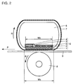
- Fig. 2 is a model diagram schematically showing the structure of a heating/fixing unit comprising a ceramic heater according to another embodiment of the present invention. As shown in Fig. 2, this structure is different from that of Fig. 1 in a point that a plurality of heat generators 2 are formed on a surface of a ceramic substrate 1 which is opposite to that facing a paper 9. Due to the plurality of linear heat generators 2 formed on the surface of the ceramic substrate 1, it is possible to uniformly heat the ceramic substrate 1. Thus, uniform heating of the ceramic substrate 1 can be implemented.
- Figs. 3A to 3C are sectional views schematically showing the structures of conventional and inventive plate-type ceramic heaters respectively.
- a heat generator 2 is formed on a surface (lower surface in the figure) of a ceramic substrate 1 facing a paper in the conventional plate-type ceramic heater.
- a protective glass layer 5 is formed to cover the heat generator 2.
- the heat generator 2 is formed on the surface (upper surface in the figure) of the ceramic substrate 1 which is opposite to that facing the paper 9 in the ceramic heater according to one embodiment of the present invention.
- the protective glass layer 5 is formed to cover the heat generator 2.
- Fig. 3C illustrates the structure of a ceramic heater according to still another embodiment of the present invention.
- a heat generator 2 is formed on the overall surface of a ceramic substrate 1.
- a protective glass layer 5 is formed on the heat generator 2.
- Such a ceramic heater is called a bulk heater.
- the dimensions of the respective ceramic heaters are set as follows:
- the heat generator 2 has a thickness t 0 of 0.01 mm and a width W 1 of 1.5 mm
- the ceramic substrate 1 has a thickness t 1 of 0.635 mm and a width W 2 of 9.0 mm
- the protective glass layer 5 has a thickness t 2 of 0.080 mm.
- the heat generator 2 has a thickness t 0 of 0.01 mm and a width W 1 of 1.5 mm, the ceramic substrate 1 has a thickness t 1 of 0.635 mm and a width W 2 of 9.0 mm, and the protective glass layer 5 has a thickness t 2 of 0.080 mm.
- the heat generator 2 has a thickness t 0 of 0.3 mm, the ceramic substrate 1 has a thickness t 1 of 0.4 mm and a width W 2 of 9.0 mm, and the protective glass layer 5 has a thickness t 2 of 0.080 mm.
- Table 3 shows heat resistance values approximately calculated as to the structures of the respective heaters.
- Table 3 Heater Structure Fig. 3A Fig. 3B Fig. 3C Substrate Material Al 2 O 3 (AlN) AlN AlN Heat Resistance (°C/W) 8.19 1.15 0.045
- the ceramic heater having the structure of Fig. 3B according to the present invention exhibits a lower heat resistance value as compared with the conventional ceramic heater shown in Fig. 3A.
- the heat resistance value of the ceramic heater shown in Fig. 3A remains unchanged whether the ceramic substrate 1 is made of Al 2 O 3 or AlN. This is because the heat resistance value is calculated only with respect to heat which is generated from the heat generator 2 and downwardly transmitted in the figure, i.e., toward the paper. In practice, however, the heat is also transmitted to the alumina or aluminum nitride forming the ceramic substrate 1 in the structure shown in Fig. 3A.
- the heat is transmitted at a higher speed and temperature rise/soaking more quickly advances in the aluminum nitride, and hence actual heat resistance is considerably reduced when the aluminum nitride is employed as compared with alumina also in the structure shown in Fig. 3A.
- the heater has the structure shown in Fig. 3C, on the other hand, the heat resistance is further reduced.
- the aforementioned heat transmission characteristics also apply to the case of employing boron nitride or silicon carbide.
- the heat resistance can be further reduced in this direction in the plate-type ceramic heater. Further, it is possible to further reduce the heat resistance along this direction by providing the heat generator not in the form of lines but in the form of a surface on the surface of the ceramic substrate.
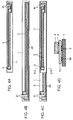
- Figs. 4A to 4D illustrate a ceramic heater according to a further embodiment of the present invention.
- temperature detector electric circuit layers 3 are formed on a surface of an insulating substrate 11. Electrode layers 41 are connected to first ends of the temperature detector electric circuit layers 3.
- a temperature detector 4 is provided on second ends of the temperature detector electric circuit layers 3.
- the insulating substrate 11 can be made of Al 2 O 3 , ZrO 2 , glass, Si 3 N 4 or AlN.
- Conductors employed for the electric circuit layers 3 provided in the vicinity of the heater are preferably prepared from a metal which is hard to oxidize such as a noble metal such as Ag, Au or Pt or an alloy thereof.
- a heat generator 2 is formed on a surface of a ceramic substrate 1 consisting of an aluminum nitride sintered body.
- An electric circuit layer 22 is formed on the surface of the ceramic substrate 1 to be connected to and extend in parallel with the heat generator 2. Electrode layers 21 are formed to be connected with first end portions of the heat generator 2 and the electric circuit layer 22 respectively.
- the insulating substrate 11 which is structured as shown in Fig. 4A is arranged on the ceramic substrate 1 having the heat generator 2 which is structured as shown in Fig. 4B.
- Fig. 4C is a plan view showing the ceramic heater having this structure.
- Fig. 4D is a sectional view taken along the line D - D in Fig. 4C.
- the temperature detector 4 is located immediately above the heat generator 2 through the insulating substrate 11. Thus, responsibility for temperatures can be improved.
- the insulating substrate 11 may simply be provided on the heat generator 2, and the ceramic substrate 1 may be connected with the insulating substrate 11 by any method.
- the prescribed heat generator 2, the electric circuit layer 22 and the electrode layers 21 are formed on the ceramic substrate 1 by thick film screen printing. Then, the electric circuit layers 3 and the electrode layers 41 are formed also on the surface of the insulating substrate 11 by a similar method to the above. Thereafter the insulating substrate 11 is placed on a prescribed position of the ceramic substrate 1, and fired in the atmosphere. Thus, the heat generator 2, the electric circuit layer 22 and the electrode layers 21 can be baked onto and connected with both of the ceramic substrate 1 and the insulating substrate 11.
- the heat generator 2 As another method of connecting the ceramic substrate 1 with the insulating substrate 11, the heat generator 2, the electric circuit layer 22, the electrode layers 21, the electric circuit layers 3 and the electrode layers 41 are separately baked onto both of the ceramic substrate 1 and the insulating substrate 11. Thereafter an overcoat glass layer for protecting the heat generator 2 is baked and dried on the ceramic substrate 1.
- the insulating substrate 11 is fixed to a prescribed position on the ceramic substrate 1, and the glass is baked. The glass is baked to both substrates, whereby the ceramic substrate 1 and the insulating substrate 11 can be connected to each other.
- Samples of the ceramic heaters shown in Figs. 1, 2 and 7 were prepared by employing Al 2 O 3 and AlN as the materials for the ceramic substrates. Each sample of the ceramic heaters was prepared in the following method:
- a ceramic substrate 1 of 300 mm by 10 mm by 0.7 mm was prepared from an Al 2 O 3 or AlN sintered body. Its surface was finished into 2 ⁇ m in ten-point average height roughness Rz, and paste mainly composed of a noble metal such as Ag or Pt was applied onto a prescribed position of the substrate by screen printing, thereby forming a heat generator 2. Paste containing a metal component such as Ag was applied onto a prescribed position by screen printing, thereby forming an electrode connected to the heat generator 2. Further, Ag-Pd was applied onto the substrate 1 by screen printing, thereby forming temperature detector electric circuit layers 3. A temperature detector 4 was provided on the temperature detector electric circuit layers 3. Thereafter the ceramic substrate 1 was fired in the atmosphere at a temperature of 900°C.
- the resistance value of the heat generator 2 was set at 20 ⁇ .
- Glass was applied to the fired ceramic substrate 1 by screen printing for protecting the electric circuit layers 3 and the heat generator 2, and fired in the atmosphere at a temperature of 600°C.
- a protective glass layer 5 of 60 ⁇ m in thickness was formed.
- the substrate 1 exhibited longitudinal warpage and waviness of 1.8 mm and 2.0 mm respectively.
- the AlN sintered body employed in the aforementioned method of preparing each ceramic heater was prepared as follows:
- 0.8 parts by weight of a sintering assistant was added to 100 parts by weight of AlN powder with addition of prescribed amounts of an organic binder and an organic solvent, and these materials were mixed with each other by a ball mill mixing method. Thereafter the obtained slurry was sheet-formed by a doctor blade coater. The obtained sheet was cut into prescribed dimensions, and degreased in a non-oxidizing atmosphere at a temperature of 800 to 900°C. Alternatively, the sheet may be degreased in an oxidizing atmosphere such as the atmosphere at a temperature of not more than 600°C. If the degreasing is performed in an oxidizing atmosphere at a temperature exceeding 600°C, oxidation reaction unpreferably progresses on the AlN powder surface to reduce heat conductivity of the obtained sintered body.
- the degreased sheet was fired in a non-oxidizing atmosphere at a temperature of 1700 to 1900°C.
- a temperature of 1700 to 1900°C a temperature of 1700 to 1900°C.
- the AlN sintered body prepared in the aforementioned manner exhibited heat conductivity of about 170 W/mK, flexural strength of 30 kg/mm 2 and a mean particle diameter of 8 ⁇ m.
- the diameters of the particles forming AlN are increased as the sintering temperature is increased. While the particle diameters are also increased as the sintering time is increased, the influence by the sintering temperature is larger than that by the sintering time.
- the AlN sintering body is formed by bonding of the particles.
- the flexural strength of the AlN sintered body is in proportion to the bonding strength between the particles and the connection areas of the particles.
- Samples of the heating/fixing units shown in Figs. 1, 2 and 7 were prepared by employing the samples of the ceramic heaters shown in these figures prepared in the aforementioned manner.
- the heat generators 2 were 1.5 mm in thickness, while the sample of the ceramic heater shown in Fig. 2 was provided with three linear heat generators 2 of 0.5 mm in width.
- the respective samples of the heating/fixing units were subjected to evaluation of fixability levels for toner images with respect to papers. The fixability of each sample was evaluated as follows: A toner was applied to the overall surface of a paper of the A4 size under Japanese Industrial Standards, which was in a state before introduction into a fixing unit of a printer.
- the toner was fixed to the paper by the sample of the ceramic heater shown in each of Figs. 1, 2 and 7.
- the fixing rate was set by adjusting the speed of a motor for driving the pressure roller 8.
- the width W 3 of the contact part defined between the heat-resistant resin film 7 and the pressure roller 8 and the load for fixation were set at levels shown in Table 1 in response to the fixing rate.
- Table 4 shows conditions in and results of the evaluation test.
- the unit "ppm" for the fixing rates indicates the number of papers which are fed per minute.
- the fixing loads indicate absolute loads applied to the papers 9 by the pressure rollers 8 and the resin films 7.
- Al 2 O 3 " and "AlN” indicate that alumina and aluminum nitride sintered bodies were employed as the materials for the ceramic substrates 1 respectively.
- Fig. 1", “Fig. 2” and “Fig. 3” indicate that fixing tests were made through the samples of the ceramic heaters shown in these figures respectively.
- “20 W/mK” and "170 W/mK” indicate the heat conductivity values of the ceramic substrates 1.
- the fixability levels were evaluated on first, second, fourth, sixth, eighth, twelfth and sixteenth papers fed to each heating/fixing unit. The first paper was fed to each heating/fixing unit after 15 seconds from power supply to the ceramic heater 10.
- the fixability level of " ⁇ " is readily attained in the structure of the conventional ceramic heater (Fig. 7) when the fixing rate is 8 ppm, even if the load is 4 kg (the width W 3 of the contact part is 2 mm). This is conceivably because the width of an actual soaking part varies with the heat radiation property regardless of the width of the contact part.
- Table 5 shows power consumed before complete fixation of the first paper, the transfer material, which was measured with an integrating wattmeter as to each condition. Referring to each column of Table 5, the left values indicate those of power consumption required for temperature rise, and right values show those required for fixation respectively.
- the ceramic substrates are made of alumina, fixability levels are deteriorated as the fixation rates are increased even if power consumption levels are increased, due to high temperature distribution.
- the ceramic substrates are made of aluminum nitride, on the other hand, heat can be effectively transmitted due to uniform temperature distribution in the substrates and small heat resistance, and the power consumption levels are reduced in order of Fig. 7 > Fig. 1 > Fig. 2.
- preferable heat conductivity levels of the ceramic substrates were at least 50 W/mK, and the fixability levels were improved as the heat conductivity values were increased.
- "o" indicates that a toner formed on each paper was not in the least separated.
- Aluminum nitride sintered bodies each having a mean particle diameter of 5.5 ⁇ m, flexural strength of 42 kg/mm 2 and heat conductivity of 170 W/mK were prepared by forming sheets with various sintering assistants and sintering the sheets at a temperature of 1700°C, to prepare substrates of 300 mm by 10 mm by 0.7 mm, similarly to the above.
- the ten-point average height roughness of the surface of each substrate was 2 ⁇ m.
- Respective printed/baked layers including heat generators containing noble metals such as Ag or Pt, electrode layers containing Ag and temperature detector circuits of Ag-Pd were formed on the substrates followed by baking of protective glass layers, similarly to the above.
- Powder serving as a prescribed conductor component was added to and mixed with AlN powder and thereafter sheet-formed by a doctor blade coater.
- a heat generator 2 was formed.
- a ceramic substrate 1 of AlN was sheet-formed in a similar manner to Example 1, with no addition of conductor powder.
- These sheets were stacked with each other and cut into prescribed dimensions, and thereafter degreased in a non-oxidizing atmosphere at a temperature of 600 to 900°C.
- the degreasing may be performed in an oxidizing atmosphere such as the atmosphere at a temperature of not more than 600°C.
- the degreased sheet was fired in a non-oxidizing atmosphere at a temperature of 1700 to 1900°C.
- thicknesses corresponding to those of the heat generator 2 and the ceramic substrate 1 were 0.3 mm and 0.4 mm respectively. The total thickness was 0.7 mm. This sintered body was cut into dimensions of 300 mm by 10 mm.
- an Al 2 O 3 substrate of 150 mm by 8 mm by 0.3 mm was prepared.
- a prescribed circuit was formed on this substrate, and a thermistor serving as a temperature detector was mounted.
- the substrate employed herein may simply be capable of ensuring insulation between the same and a heat generator, and may alternatively be prepared from ZrO 2 , glass or AlN.
- a conductor employed for forming the circuit may simply have conductivity.
- the conductor is preferably prepared from a metal which is hard to oxidize such as a noble metal such as Ag, Au or Pt, or an alloy thereof, since the circuit is formed in the vicinity of the heat generator.
- the fixability evaluation test was made under fixing pressure of 4 kg and a fixing rate of 8 ppm. As clearly understood from Table 7, the fixability levels were improved by increasing the contents of the conductor components.
- Substrates having lengths of 300 mm, thicknesses of 0.7 mm and various widths shown in Table 8 were prepared from aluminum sintered bodies of 5.5 ⁇ m in mean particle diameter, 42 kg/mm 2 in flexural strength and 170 W/mK in heat conductivity obtained by the sheet forming method of Example 1. Surfaces of the substrates were finished into 2 ⁇ m in ten-point average height roughness Rz. Heat generators, electrodes and temperature detector electric circuit layers were baked to the ceramic substrates of various widths similarly to Example 1, to prepare samples of the ceramic heater shown in Fig. 1.
- Samples of the ceramic heater shown in Fig. 1 were formed by alumina substrates prepared in Example 1 and fixability levels were evaluated on substrates having various widths.
- the fixability level was "x" when the substrate width was not more than 5 mm under a fixing rate of 8 ppm and a fixing load of 4 kg, while the fixability level of " ⁇ " was confirmed up to a substrate width of 6 mm (in this case, the width of the contact part was 4 mm, and the ratio of the width of the substrate to that of the contact part was 1.5) when the load was increased to 8 kg.
- a fixing rate of 12 ppm it was impossible to fix the toner even if the substrate width was increased to 10 mm.
- this ratio is reduced to 1.5 at the minimum in a ceramic heater employing an alumina substrate in order to ensure prescribed fixability, while it is understood that prescribed fixability can be ensured even if the ratio is reduced to below 1.4, when the ceramic heater is prepared from an aluminum nitride substrate according to the present invention.
- a sample of the ceramic heater having the structure shown in Fig. 7 was prepared from the aforementioned alumina substrate, and its fixability was similarly evaluated under the aforementioned conditions. Consequently, the lower limit of the substrate width capable of ensuring the fixability level of " ⁇ " was 2.0 mm when the fixing rate was 8 ppm and the fixing load was 4 kg, while the fixability level was " ⁇ " or "x" when the substrate width was 1.6 mm.
- the power consumption evaluated similarly to the above was increased by about 4 to 11 % under fixing conditions corresponding to those in Table 8.
- Substrates having lengths of 300 mm, widths of 9 mm and various thicknesses shown in Table 9 were prepared from the same aluminum sintered bodies as those employed in Example 3. Heat generators of 1.5 mm in width, electrodes and temperature detector electrode circuit layers were baked on these substrates similarly to Example 1, to prepare samples of the ceramic heaters shown in Figs. 1 and 7. Further, samples of the heating/fixing units shown in Figs. 1 and 7 were prepared from these ceramic heater samples.
- the respective heating/fixing unit samples were subjected to evaluation of fixability levels for toners with respect to papers. Under conditions of a fixing rate of 16 ppm and a fixing load of 13 kg, fixability levels were evaluated similarly to Example 1, except that 1000 papers were fed in this Example, and values of power consumption required for fixing the first papers were measured. Table 9 shows the results.
- Fig. 7 indicates heating/fixing unit samples prepared from the samples of the ceramic heater shown in Fig. 7
- Fig. 1 indicates heating/fixing unit samples prepared from the samples of the ceramic heater shown in Fig. 1 according to the present invention.
- Table 9 Heater Structure Substrate Thickness (mm) Heat Generator Width (mm) Fixability Power Consumption (Wh) in Temperature Rise in Fixation Fig. 7 0.7 0.5 ⁇ 0.92 0.47 Fig. 7 0.6 0.5 ⁇ 0.84 0.45 Fig. 7 0.4 0.5 ⁇ 0.65 0.43 Fig. 7 0.3 unintegrable as heater due to remarkable warpage Fig. 1 0.7 0.5 ⁇ 0.85 0.43 Fig. 1 0.6 0.5 ⁇ 0.77 0.41 Fig. 1 0.4 0.5 ⁇ 0.60 0.41
- the power consumption in temperature rise can be reduced by about 8 % in case of employing the ceramic heater of the structure shown in Fig. 1 as compared with that of the structure shown in Fig. 7.
Landscapes
- Chemical & Material Sciences (AREA)
- Engineering & Computer Science (AREA)
- Ceramic Engineering (AREA)
- Physics & Mathematics (AREA)
- General Physics & Mathematics (AREA)
- Surface Heating Bodies (AREA)
- Resistance Heating (AREA)
- Fixing For Electrophotography (AREA)
- Control Of Resistance Heating (AREA)
Applications Claiming Priority (4)
| Application Number | Priority Date | Filing Date | Title |
|---|---|---|---|
| JP294594/95 | 1995-11-13 | ||
| JP29459495 | 1995-11-13 | ||
| JP284999/96 | 1996-10-28 | ||
| JP8284999A JPH09197861A (ja) | 1995-11-13 | 1996-10-28 | ヒーターおよびそれを備えた加熱定着装置 |
Publications (2)
| Publication Number | Publication Date |
|---|---|
| EP0773485A2 true EP0773485A2 (fr) | 1997-05-14 |
| EP0773485A3 EP0773485A3 (fr) | 1998-10-28 |
Family
ID=26555704
Family Applications (1)
| Application Number | Title | Priority Date | Filing Date |
|---|---|---|---|
| EP96118060A Withdrawn EP0773485A3 (fr) | 1995-11-13 | 1996-11-11 | Elément chauffant et unité de chauffage ou de fixage comprenant cet élément |
Country Status (4)
| Country | Link |
|---|---|
| US (1) | US5732318A (fr) |
| EP (1) | EP0773485A3 (fr) |
| JP (1) | JPH09197861A (fr) |
| CA (1) | CA2189934C (fr) |
Cited By (4)
| Publication number | Priority date | Publication date | Assignee | Title |
|---|---|---|---|---|
| EP0914022A3 (fr) * | 1997-10-30 | 1999-09-15 | Sumitomo Electric Industries, Ltd. | Elément chauffant en nitrure d'aluminium |
| EP0903646A3 (fr) * | 1997-09-17 | 1999-12-22 | Sumitomo Electric Industries, Ltd. | Elément chauffant en céramique pour le fixage d'images de toner |
| EP0984339A3 (fr) * | 1998-08-31 | 2001-07-25 | Canon Kabushiki Kaisha | Appareil de chauffage d'une image et élément chauffant |
| CN110703575A (zh) * | 2012-11-21 | 2020-01-17 | 佳能株式会社 | 图像加热设备 |
Families Citing this family (23)
| Publication number | Priority date | Publication date | Assignee | Title |
|---|---|---|---|---|
| JP3769841B2 (ja) * | 1996-10-28 | 2006-04-26 | 住友電気工業株式会社 | 加熱定着装置 |
| JP3372811B2 (ja) * | 1997-02-03 | 2003-02-04 | キヤノン株式会社 | 加熱定着装置 |
| US6055403A (en) * | 1998-01-28 | 2000-04-25 | Canon Kabushiki Kasiha | Fixing member fixing apparatus and electrophotographic apparatus using them |
| US6090305A (en) * | 1999-03-15 | 2000-07-18 | Lexmark International, Inc. | Heater for use in electrophotographic image fixing device |
| JP2001196152A (ja) | 2000-01-13 | 2001-07-19 | Sumitomo Electric Ind Ltd | セラミックスヒータ |
| JP4529690B2 (ja) * | 2000-01-20 | 2010-08-25 | 住友電気工業株式会社 | 半導体製造装置用ウェハ保持体およびその製造方法ならびに半導体製造装置 |
| JP2002031976A (ja) | 2000-05-10 | 2002-01-31 | Sumitomo Electric Ind Ltd | トナー定着器用セラミックスヒータ及びその製造方法 |
| JP2002031972A (ja) | 2000-05-10 | 2002-01-31 | Sumitomo Electric Ind Ltd | トナー定着器用セラミックスヒータ及びその製造方法 |
| JP2002008826A (ja) * | 2000-06-16 | 2002-01-11 | Ibiden Co Ltd | 半導体製造・検査装置用セラミックヒータ |
| JP2002139932A (ja) | 2000-11-01 | 2002-05-17 | Sumitomo Electric Ind Ltd | 加熱定着装置 |
| JP2003186321A (ja) * | 2001-10-09 | 2003-07-04 | Canon Inc | 像加熱装置 |
| JP4483161B2 (ja) * | 2002-08-13 | 2010-06-16 | 住友電気工業株式会社 | 窒化アルミニウム焼結体、メタライズ基板、ヒータ、治具および窒化アルミニウム焼結体の製造方法 |
| US6801745B1 (en) * | 2003-03-27 | 2004-10-05 | Lexmark International, Inc. | Fuser for an electrophotographic printer and method of using same |
| US6865351B2 (en) * | 2003-04-29 | 2005-03-08 | Lexmark International, Inc. | Method of using a fuser for a color electrophotographic printer |
| US6879803B2 (en) * | 2003-04-29 | 2005-04-12 | Lexmark International, Inc. | Belt fuser for a color electrophotographic printer |
| US7039352B2 (en) * | 2003-07-10 | 2006-05-02 | Hewlett-Packard Development Company, L.P. | Thermally self-regulating fusing system for thermal transfer overcoat device including stationary heating assembly |
| US7466951B2 (en) * | 2004-09-29 | 2008-12-16 | Lexmark International, Inc. | Heater assembly in a fuser with a raised resilient pad in an electrophotographic imaging device |
| US7672631B2 (en) * | 2006-12-11 | 2010-03-02 | Lexmark International, Inc. | Fuser assembly having heater element with spaced-apart features |
| JP2008233886A (ja) * | 2007-02-19 | 2008-10-02 | Ricoh Co Ltd | 定着装置及び画像形成装置 |
| US8489006B2 (en) * | 2008-11-26 | 2013-07-16 | Eastman Kodak Company | Externally heated fuser device with extended nip width |
| US9798279B2 (en) * | 2015-07-01 | 2017-10-24 | Xerox Corporation | Printed thermocouples in solid heater devices |
| CN207869432U (zh) * | 2018-03-07 | 2018-09-14 | 东莞市国研电热材料有限公司 | 一种多温区陶瓷发热体 |
| JP2025034950A (ja) * | 2023-08-31 | 2025-03-13 | ブラザー工業株式会社 | 定着装置 |
Citations (4)
| Publication number | Priority date | Publication date | Assignee | Title |
|---|---|---|---|---|
| JPS63313182A (ja) | 1987-06-16 | 1988-12-21 | Canon Inc | 像加熱装置 |
| JPH01263679A (ja) | 1988-04-15 | 1989-10-20 | Canon Inc | 定着装置 |
| JPH02157878A (ja) | 1988-12-12 | 1990-06-18 | Canon Inc | 画像加熱定着装置 |
| JPH05135849A (ja) | 1991-11-11 | 1993-06-01 | Canon Inc | ヒーター及び定着装置 |
Family Cites Families (9)
| Publication number | Priority date | Publication date | Assignee | Title |
|---|---|---|---|---|
| US4998121A (en) * | 1988-10-03 | 1991-03-05 | Canon Kabushiki Kaisha | Image forming apparatus |
| US5262834A (en) * | 1988-12-06 | 1993-11-16 | Canon Kabushiki Kaisha | Image fixing apparatus |
| US5162634A (en) * | 1988-11-15 | 1992-11-10 | Canon Kabushiki Kaisha | Image fixing apparatus |
| JPH04284481A (ja) * | 1991-03-14 | 1992-10-09 | Hitachi Koki Co Ltd | 熱定着装置 |
| US5499087A (en) * | 1991-04-22 | 1996-03-12 | Hitachi, Ltd. | Heat fixing device and electrophotographic apparatus incorporating the same having a PTC heating element received in a recess of a holder |
| JP3170857B2 (ja) * | 1992-03-27 | 2001-05-28 | キヤノン株式会社 | 加熱装置 |
| JP3161114B2 (ja) * | 1992-12-29 | 2001-04-25 | キヤノン株式会社 | 加熱装置 |
| JPH07201455A (ja) * | 1993-12-28 | 1995-08-04 | Canon Inc | セラミックヒータ |
| JPH07234596A (ja) * | 1994-02-21 | 1995-09-05 | Canon Inc | 像加熱装置 |
-
1996
- 1996-10-28 JP JP8284999A patent/JPH09197861A/ja active Pending
- 1996-11-08 US US08/746,443 patent/US5732318A/en not_active Expired - Lifetime
- 1996-11-08 CA CA002189934A patent/CA2189934C/fr not_active Expired - Fee Related
- 1996-11-11 EP EP96118060A patent/EP0773485A3/fr not_active Withdrawn
Patent Citations (4)
| Publication number | Priority date | Publication date | Assignee | Title |
|---|---|---|---|---|
| JPS63313182A (ja) | 1987-06-16 | 1988-12-21 | Canon Inc | 像加熱装置 |
| JPH01263679A (ja) | 1988-04-15 | 1989-10-20 | Canon Inc | 定着装置 |
| JPH02157878A (ja) | 1988-12-12 | 1990-06-18 | Canon Inc | 画像加熱定着装置 |
| JPH05135849A (ja) | 1991-11-11 | 1993-06-01 | Canon Inc | ヒーター及び定着装置 |
Cited By (6)
| Publication number | Priority date | Publication date | Assignee | Title |
|---|---|---|---|---|
| EP0903646A3 (fr) * | 1997-09-17 | 1999-12-22 | Sumitomo Electric Industries, Ltd. | Elément chauffant en céramique pour le fixage d'images de toner |
| EP0914022A3 (fr) * | 1997-10-30 | 1999-09-15 | Sumitomo Electric Industries, Ltd. | Elément chauffant en nitrure d'aluminium |
| US6084221A (en) * | 1997-10-30 | 2000-07-04 | Sumitomo Electric Industries, Ltd. | Aluminum nitride heater |
| EP0984339A3 (fr) * | 1998-08-31 | 2001-07-25 | Canon Kabushiki Kaisha | Appareil de chauffage d'une image et élément chauffant |
| US6423941B1 (en) | 1998-08-31 | 2002-07-23 | Canon Kabushiki Kaisha | Image heating apparatus and heater |
| CN110703575A (zh) * | 2012-11-21 | 2020-01-17 | 佳能株式会社 | 图像加热设备 |
Also Published As
| Publication number | Publication date |
|---|---|
| CA2189934C (fr) | 2003-09-09 |
| EP0773485A3 (fr) | 1998-10-28 |
| JPH09197861A (ja) | 1997-07-31 |
| CA2189934A1 (fr) | 1997-05-14 |
| US5732318A (en) | 1998-03-24 |
Similar Documents
| Publication | Publication Date | Title |
|---|---|---|
| EP0773485A2 (fr) | Elément chauffant et unité de chauffage ou de fixage comprenant cet élément | |
| EP1711034B1 (fr) | Appareil chauffant ceramique et procede de production associe | |
| CA2217149C (fr) | Dispositif de fixation thermique | |
| EP1154336A1 (fr) | Elément chauffant en céramique pour une unité de fixage de toner et procédé de fabrication de l'élément chauffant | |
| EP1154337B1 (fr) | Elément chauffant en céramique pour des unités de fixage et méthode de fabrication de cet élément de chauffage | |
| EP3608113B1 (fr) | Tête thermique et imprimante thermique | |
| JP2006301661A (ja) | ヒーターおよびそれを備えた加熱定着装置 | |
| US6078027A (en) | Ceramic fixing heater containing silicon nitride | |
| JPH11273836A (ja) | 定着ヒ―タおよび画像形成装置 | |
| JP2740207B2 (ja) | 定着用加熱体、定着装置および事務用機器 | |
| JP2009140841A (ja) | 加熱体、及びこの加熱体を有する像加熱装置 | |
| JPH11174875A (ja) | 加熱定着装置 | |
| JPH11296006A (ja) | ヒ―タ、定着装置および画像形成装置 | |
| EP0709670A1 (fr) | Elément chauffant à faible consommation d'énergie | |
| EP4075202B1 (fr) | Dispositif de chauffage et appareil de formation d'images | |
| JPH0582304A (ja) | セラミツクヒータユニツト | |
| EP0761620A1 (fr) | Rouleau chauffant et procédé pour sa fabrication | |
| JPH11174874A (ja) | 加熱定着装置 | |
| JPH07266594A (ja) | サーマルヘッド | |
| GB2442890A (en) | A method of manufacturing a ceramic heater | |
| JPH11327334A (ja) | 定着用ヒータ | |
| JPH08207331A (ja) | サーマルヘッド | |
| JPH01207779A (ja) | 加熱定着ロールの抵抗発熱体層形成方法 | |
| JPH10104987A (ja) | 定着用ヒートローラ及び定着装置 | |
| JP2000323263A (ja) | 発熱素子 |
Legal Events
| Date | Code | Title | Description |
|---|---|---|---|
| PUAI | Public reference made under article 153(3) epc to a published international application that has entered the european phase |
Free format text: ORIGINAL CODE: 0009012 |
|
| AK | Designated contracting states |
Kind code of ref document: A2 Designated state(s): DE FR GB IT |
|
| PUAL | Search report despatched |
Free format text: ORIGINAL CODE: 0009013 |
|
| AK | Designated contracting states |
Kind code of ref document: A3 Designated state(s): DE FR GB IT |
|
| 17P | Request for examination filed |
Effective date: 19981119 |
|
| 17Q | First examination report despatched |
Effective date: 19991216 |
|
| STAA | Information on the status of an ep patent application or granted ep patent |
Free format text: STATUS: THE APPLICATION IS DEEMED TO BE WITHDRAWN |
|
| 18D | Application deemed to be withdrawn |
Effective date: 20110222 |