EP0774620A1 - Brenner für flüssigen oder gasförmigen Brennstoff mit sehr niedriger Stickoxidemission - Google Patents
Brenner für flüssigen oder gasförmigen Brennstoff mit sehr niedriger Stickoxidemission Download PDFInfo
- Publication number
- EP0774620A1 EP0774620A1 EP95402538A EP95402538A EP0774620A1 EP 0774620 A1 EP0774620 A1 EP 0774620A1 EP 95402538 A EP95402538 A EP 95402538A EP 95402538 A EP95402538 A EP 95402538A EP 0774620 A1 EP0774620 A1 EP 0774620A1
- Authority
- EP
- European Patent Office
- Prior art keywords
- primary air
- ring
- air duct
- cavity
- burner
- Prior art date
- Legal status (The legal status is an assumption and is not a legal conclusion. Google has not performed a legal analysis and makes no representation as to the accuracy of the status listed.)
- Granted
Links
Images


Classifications
-
- F—MECHANICAL ENGINEERING; LIGHTING; HEATING; WEAPONS; BLASTING
- F23—COMBUSTION APPARATUS; COMBUSTION PROCESSES
- F23M—CASINGS, LININGS, WALLS OR DOORS SPECIALLY ADAPTED FOR COMBUSTION CHAMBERS, e.g. FIREBRIDGES; DEVICES FOR DEFLECTING AIR, FLAMES OR COMBUSTION PRODUCTS IN COMBUSTION CHAMBERS; SAFETY ARRANGEMENTS SPECIALLY ADAPTED FOR COMBUSTION APPARATUS; DETAILS OF COMBUSTION CHAMBERS, NOT OTHERWISE PROVIDED FOR
- F23M5/00—Casings; Linings; Walls
- F23M5/02—Casings; Linings; Walls characterised by the shape of the bricks or blocks used
- F23M5/025—Casings; Linings; Walls characterised by the shape of the bricks or blocks used specially adapted for burner openings
-
- F—MECHANICAL ENGINEERING; LIGHTING; HEATING; WEAPONS; BLASTING
- F23—COMBUSTION APPARATUS; COMBUSTION PROCESSES
- F23C—METHODS OR APPARATUS FOR COMBUSTION USING FLUID FUEL OR SOLID FUEL SUSPENDED IN A CARRIER GAS OR AIR
- F23C6/00—Combustion apparatus characterised by the combination of two or more combustion chambers or combustion zones, e.g. for staged combustion
- F23C6/04—Combustion apparatus characterised by the combination of two or more combustion chambers or combustion zones, e.g. for staged combustion in series connection
- F23C6/045—Combustion apparatus characterised by the combination of two or more combustion chambers or combustion zones, e.g. for staged combustion in series connection with staged combustion in a single enclosure
-
- F—MECHANICAL ENGINEERING; LIGHTING; HEATING; WEAPONS; BLASTING
- F23—COMBUSTION APPARATUS; COMBUSTION PROCESSES
- F23C—METHODS OR APPARATUS FOR COMBUSTION USING FLUID FUEL OR SOLID FUEL SUSPENDED IN A CARRIER GAS OR AIR
- F23C7/00—Combustion apparatus characterised by arrangements for air supply
- F23C7/02—Disposition of air supply not passing through burner
-
- F—MECHANICAL ENGINEERING; LIGHTING; HEATING; WEAPONS; BLASTING
- F23—COMBUSTION APPARATUS; COMBUSTION PROCESSES
- F23D—BURNERS
- F23D17/00—Burners for combustion simultaneously or alternately of gaseous or liquid or pulverulent fuel
- F23D17/002—Burners for combustion simultaneously or alternately of gaseous or liquid or pulverulent fuel gaseous or liquid fuel
Definitions
- the subject of the present invention is a burner for liquid or gaseous fuel comprising a primary air supply duct, means for injecting the fuel into a hearth disposed inside said duct, in the axis of the latter, and comprising multiple orifices creating several divergent and independent flames in the hearth, a flame stabilizer arranged coaxially inside said duct, and several secondary air injectors, as much as of flames, arranged around the axis of the burner and at the front of the fuel injection means in positions such that each injector provides an additional flow to each flame after a first combustion phase.
- Such a burner which is the subject of French patent n ° 93 07863 in the name of the applicant, makes it possible to reduce the emission of nitrogen oxide to a very low level without reducing the power of the burner nor increasing the content in unburnt exhaust gases.
- each secondary air injector is supplied by a duct constituted by a metal tube projecting inside the hearth. Although they are cooled by the air which circulates there, these tubes subjected to the radiation of the flame and to the convection of the hot gases of the hearth can be brought to relatively high temperature (800 ° - 900 ° C), according to the regimes Operating. Even if they are made of refractory steel, their resistance over time is problematic.
- the object of the present invention is to remedy this drawback by avoiding the use of metal parts to produce the part of the burner subjected to the radiation of flames.
- the burner object of the present invention is characterized in that it comprises a ring of refractory material which surrounds the front end of the primary air duct, in that this ring comprises on its front face a cavity in the form of a bowl, in that said primary air duct opens onto the bottom of said cavity, and in that said secondary air ducts consist of passages formed in said ring and opening onto the front face of the part of the ring bordering said cavity by orifices constituting said secondary air injectors.
- bowl-shaped cavity is meant a cavity with a practically flat bottom and the diameter of which is several times the depth.
- the orifices through which said secondary air ducts open into the hearth are angularly offset, in the direction of rotation of the primary air, by relative to the radial planes containing the axes of the corresponding orifices of the fuel injection means, and means are provided for adjusting this angular offset.
- the means of injection fuel being generally constituted by a cane provided at its front end (fireplace side) with an injection head pierced with orifices distributed around its axis, which coincides with the axes of the burner and of the primary air duct, , for example, mount the cane on the burner body so that it can rotate around its axis relative to the ring of refractory material and provide means, accessible from the rear of the burner, to control its rotation.
- the burner can be equipped with lances for injecting an additional gaseous fuel arranged in the primary air duct and the ends of which are located near the means for injecting the main fuel, around them.
- Other lances for injecting a gaseous fuel, the ends of which are close to the secondary air outlet orifices can be placed in the primary air duct or in passages formed in the ring of refractory material.
- the burner shown in Figures 1 and 2 is mounted on a wall 10 of a hearth 12.
- the burner body is constituted by a metal base 14 used for its attachment to the wall 10, by a primary air duct 16 fixed in a central opening of the base it passes through and by a secondary air supply box 18 fixed on the rear face of the base, around the primary air duct.
- the duct 16 and the box 18 are connected to a air supply and valves allow to regulate the primary and secondary air flows.
- a fuel injection pipe 20 is arranged in the axis of the primary air duct 16.
- This pipe comprises at its end an injection head 21 comprising several orifices or nozzles making it possible to create several independent and divergent flames in the hearth 12.
- a flame stabilizer 22 is disposed in the primary air duct and fixed on the rod 20. It has a hub and inclined blades 23 making it possible to communicate to the primary air, at its outlet from the duct 16, a movement of rotation (arrow A in FIG. 2) around the axis XX of the burner, which is also the axis of said duct and of the injection head.
- the blades 23 are circumscribed by a ferrule and an annular space is arranged between the latter and the primary air duct 16.
- the injection head 21 is located in front of the plane of the stabilizer hub but set back from the end of the conduit 16.
- the burner further comprises a ring of retractable material 24 which is fixed on the front face of the base 14, around the end of the primary air duct 16.
- This ring can be formed of segments fixed individually on the base , for example by means of screws 26, which facilitates its replacement.
- a cup-shaped cavity 25 is hollowed out in the front face of the ring. The bottom of this cavity is flat and is flush with the front end of the conduit 16 and its side wall is frustoconical.
- Figure 3 shows an alternative embodiment in which the side wall of the cavity is rounded instead of being frustoconical.
- Other shapes can be adopted for the cavity, the essential being that its diameter is equal to several times its depth and that its bottom is flat or practically flat, that is to say slightly concave or frustoconical with an angle at vertex greater than 120 °.
- the ring 24 fits into an opening in the wall of the hearth provided for this purpose.
- Passages 28 are provided in the ring 24; they open, on the one hand, in the hearth 12, on the part 30 of the ring bordering the cavity 25 and, on the other hand, in the box 18, through orifices drilled in the base 14.
- the orifices 29 through which the passages 28 open into the hearth constitute secondary air injectors; they are elongated in a circumferential direction and have, for example, a rectangular or oval section.
- FIGS. 4a and 4b show an alternative embodiment in which the secondary air passages 28 are replaced by an annular passage 28 ′ formed between the ring of refractory material, the diameter of which is reduced, and a concentric envelope sheet 31.
- the ring 24 has a rim 30 whose diameter is equal to that of the ferrule 31 and which closes the passage 28 ′ on the hearth side. Notches 29 formed on the periphery of this rim communicate the passage 28 'with the hearth and allow the injection of secondary air into the latter.
- This construction method makes it possible to reduce the diameter of the ring.
- FIGS. 5a and 5b Another exemplary embodiment is shown in FIGS. 5a and 5b: the passages 28 are produced in the form of rectilinear tubes with oval section, embedded in the retracting ring.
- FIG. 2 shows, in particular, that each orifice 29 is angularly offset, in the direction of rotation A of the primary air, by an angle ⁇ relative to the plane P containing the axis of the burner and the axis of l 'corresponding orifice of the injection head 21 through which is emitted the jet of atomized fuel producing the flame F.
- This angle ⁇ must be adjusted when the burner is started.
- the fuel injection rod 20 is mounted on the body of the crusher so as to be able to rotate around the axis X-X of the burner, and a mechanism placed at the rear of the burner makes it possible to control this rotation.
- the ratio of the radius r of the primary air duct 16 to the distance R of the orifices 29 to the axis of the burner must be between 0.25 and 0.75 (preferred value 0.35).
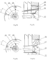
- Figures 5a and 5b show an alternative embodiment equipped with lances 32 placed inside the primary air duct 16 and opening into the hearth slightly in front of the injection head 21.
- An annular space is provided between the flame stabilizer 22 and the conduit 16 for the passage of lances which are distributed around the axis of the burner. These lances supply the burner with combustible gas.
- This burner is also equipped with a second set of combustible gas lances 34 which are housed in passages formed in the ring of refractory material 24.
- the lances 34 are located between the axis of the burner and the injection orifices d secondary air 29 and regularly distributed around this axis.
- FIGS. 6a and 6b show an alternative embodiment in which lances 34 ′ are arranged in the primary air duct 16 and comprise a terminal part bent towards the outside and situated in the cavity 25.
- the burner of the invention has the advantage of not comprising a metal part subjected to the radiation of flames in the hearth, while retaining the performance of very low emission of nitrogen oxides from the burner object of French patent n ° 93 07863 on behalf of the applicant, and to be removable from the outside, without the need to enter the home.
Landscapes
- Engineering & Computer Science (AREA)
- Chemical & Material Sciences (AREA)
- Combustion & Propulsion (AREA)
- Mechanical Engineering (AREA)
- General Engineering & Computer Science (AREA)
- Pre-Mixing And Non-Premixing Gas Burner (AREA)
Priority Applications (3)
| Application Number | Priority Date | Filing Date | Title |
|---|---|---|---|
| ES95402538T ES2160146T3 (es) | 1995-11-14 | 1995-11-14 | Quemador de combustible liquido o gaseoso con muy baja emision de oxidos de nitrogeno. |
| DE1995621707 DE69521707T2 (de) | 1995-11-14 | 1995-11-14 | Brenner für flüssigen oder gasförmigen Brennstoff mit sehr niedriger Stickoxidemission |
| EP19950402538 EP0774620B1 (de) | 1995-11-14 | 1995-11-14 | Brenner für flüssigen oder gasförmigen Brennstoff mit sehr niedriger Stickoxidemission |
Applications Claiming Priority (1)
| Application Number | Priority Date | Filing Date | Title |
|---|---|---|---|
| EP19950402538 EP0774620B1 (de) | 1995-11-14 | 1995-11-14 | Brenner für flüssigen oder gasförmigen Brennstoff mit sehr niedriger Stickoxidemission |
Publications (2)
| Publication Number | Publication Date |
|---|---|
| EP0774620A1 true EP0774620A1 (de) | 1997-05-21 |
| EP0774620B1 EP0774620B1 (de) | 2001-07-11 |
Family
ID=8221543
Family Applications (1)
| Application Number | Title | Priority Date | Filing Date |
|---|---|---|---|
| EP19950402538 Expired - Lifetime EP0774620B1 (de) | 1995-11-14 | 1995-11-14 | Brenner für flüssigen oder gasförmigen Brennstoff mit sehr niedriger Stickoxidemission |
Country Status (3)
| Country | Link |
|---|---|
| EP (1) | EP0774620B1 (de) |
| DE (1) | DE69521707T2 (de) |
| ES (1) | ES2160146T3 (de) |
Cited By (8)
| Publication number | Priority date | Publication date | Assignee | Title |
|---|---|---|---|---|
| EP0893651A1 (de) | 1997-07-22 | 1999-01-27 | Entreprise Generale De Chauffage Industriel Pillard | Brenner für flüssigen und gasförmigen Brennstoff mit niedriger Stickoxidemission |
| EP0967437A1 (de) * | 1998-06-24 | 1999-12-29 | Entreprise Generale De Chauffage Industriel Pillard | Verbesserung an Verbrennungsgeräten mit mehreren Verbrennungsluftzufuhrkanälen |
| FR2794221A1 (fr) | 1999-05-31 | 2000-12-01 | Pillard Chauffage | PERFECTIONNEMENTS AUX BRULEURS A COMBUSTIBLE LIQUIDE A BASSE EMISSION DE NOx ET DE POUSSIERES, ET AUX ATOMISEURS |
| WO2001035022A1 (en) * | 1999-10-27 | 2001-05-17 | Bloom Engineering Company, Inc. | AIR STAGED LOW-NOx BURNER |
| JP2002089807A (ja) * | 2000-09-11 | 2002-03-27 | John Zink Co Llc | 液状及びガス状燃料を燃焼する低窒素酸化物装置及び方法。 |
| FR2863691A1 (fr) * | 2003-12-15 | 2005-06-17 | Pillard Chauffage | Bruleur pour chaudiere a tubes de fumees |
| US7175423B1 (en) | 2000-10-26 | 2007-02-13 | Bloom Engineering Company, Inc. | Air staged low-NOx burner |
| EP2314921A2 (de) | 2009-10-21 | 2011-04-27 | Fives Pillard | Verfahren zum Betrieb eines Heizkessels |
Citations (7)
| Publication number | Priority date | Publication date | Assignee | Title |
|---|---|---|---|---|
| EP0007697A1 (de) * | 1978-06-19 | 1980-02-06 | John Zink Company | Brennersystem für gasförmige und/oder flüssige Brennstoffe mit minimaler NOx-Produktion |
| AT358702B (de) * | 1975-01-27 | 1980-09-25 | Manich Leo | Wirbelbrenner fuer oel- und/oder gasbetrieb |
| US4488869A (en) * | 1982-07-06 | 1984-12-18 | Coen Company, Inc. | High efficiency, low NOX emitting, staged combustion burner |
| DE4130922A1 (de) * | 1991-09-17 | 1993-03-18 | Gaswaerme Inst Ev | Brenner fuer hochtemperaturprozesse und verfahren zu seinem betreiben |
| FR2706985A1 (de) * | 1993-06-22 | 1994-12-30 | Pillard Ent Gle Chauffage Indl | |
| US5431559A (en) * | 1993-07-15 | 1995-07-11 | Maxon Corporation | Oxygen-fuel burner with staged oxygen supply |
| US5433600A (en) * | 1994-04-13 | 1995-07-18 | Industrial Technology Research Institute | Burner for the combustion of coke oven gas |
-
1995
- 1995-11-14 ES ES95402538T patent/ES2160146T3/es not_active Expired - Lifetime
- 1995-11-14 DE DE1995621707 patent/DE69521707T2/de not_active Expired - Lifetime
- 1995-11-14 EP EP19950402538 patent/EP0774620B1/de not_active Expired - Lifetime
Patent Citations (7)
| Publication number | Priority date | Publication date | Assignee | Title |
|---|---|---|---|---|
| AT358702B (de) * | 1975-01-27 | 1980-09-25 | Manich Leo | Wirbelbrenner fuer oel- und/oder gasbetrieb |
| EP0007697A1 (de) * | 1978-06-19 | 1980-02-06 | John Zink Company | Brennersystem für gasförmige und/oder flüssige Brennstoffe mit minimaler NOx-Produktion |
| US4488869A (en) * | 1982-07-06 | 1984-12-18 | Coen Company, Inc. | High efficiency, low NOX emitting, staged combustion burner |
| DE4130922A1 (de) * | 1991-09-17 | 1993-03-18 | Gaswaerme Inst Ev | Brenner fuer hochtemperaturprozesse und verfahren zu seinem betreiben |
| FR2706985A1 (de) * | 1993-06-22 | 1994-12-30 | Pillard Ent Gle Chauffage Indl | |
| US5431559A (en) * | 1993-07-15 | 1995-07-11 | Maxon Corporation | Oxygen-fuel burner with staged oxygen supply |
| US5433600A (en) * | 1994-04-13 | 1995-07-18 | Industrial Technology Research Institute | Burner for the combustion of coke oven gas |
Cited By (15)
| Publication number | Priority date | Publication date | Assignee | Title |
|---|---|---|---|---|
| EP0893651A1 (de) | 1997-07-22 | 1999-01-27 | Entreprise Generale De Chauffage Industriel Pillard | Brenner für flüssigen und gasförmigen Brennstoff mit niedriger Stickoxidemission |
| FR2766557A1 (fr) | 1997-07-22 | 1999-01-29 | Pillard Chauffage | Bruleurs a combustible liquide et gazeux a faible emission d'oxydes d'azote |
| EP0967437A1 (de) * | 1998-06-24 | 1999-12-29 | Entreprise Generale De Chauffage Industriel Pillard | Verbesserung an Verbrennungsgeräten mit mehreren Verbrennungsluftzufuhrkanälen |
| FR2780488A1 (fr) | 1998-06-24 | 1999-12-31 | Pillard Chauffage | Amelioration aux appareils a combustion comportant plusieurs conduits de transport de comburant |
| FR2794221A1 (fr) | 1999-05-31 | 2000-12-01 | Pillard Chauffage | PERFECTIONNEMENTS AUX BRULEURS A COMBUSTIBLE LIQUIDE A BASSE EMISSION DE NOx ET DE POUSSIERES, ET AUX ATOMISEURS |
| WO2001035022A1 (en) * | 1999-10-27 | 2001-05-17 | Bloom Engineering Company, Inc. | AIR STAGED LOW-NOx BURNER |
| JP2002089807A (ja) * | 2000-09-11 | 2002-03-27 | John Zink Co Llc | 液状及びガス状燃料を燃焼する低窒素酸化物装置及び方法。 |
| EP1191281A1 (de) * | 2000-09-11 | 2002-03-27 | John Zink Company,L.L.C. | Brenner mit geringen NOx Emissionen und Verfahren zum Verbrennen von flüssigen und gasförmigen Brennstoffen |
| US6422858B1 (en) | 2000-09-11 | 2002-07-23 | John Zink Company, Llc | Low NOx apparatus and methods for burning liquid and gaseous fuels |
| AU777893B2 (en) * | 2000-09-11 | 2004-11-04 | John Zink Company Llc | Low NOx apparatus and methods for burning liquid and gaseous fuels |
| KR100824483B1 (ko) * | 2000-09-11 | 2008-04-22 | 존 징크 컴파니 엘엘씨 | 액체 및 가스 연료 연소용 저 질소산화물 장치 및 방법 |
| US7175423B1 (en) | 2000-10-26 | 2007-02-13 | Bloom Engineering Company, Inc. | Air staged low-NOx burner |
| FR2863691A1 (fr) * | 2003-12-15 | 2005-06-17 | Pillard Chauffage | Bruleur pour chaudiere a tubes de fumees |
| EP1544541A1 (de) * | 2003-12-15 | 2005-06-22 | Entreprise Generale De Chauffage Industriel Pillard | Brenner für Rauchrohrkessel |
| EP2314921A2 (de) | 2009-10-21 | 2011-04-27 | Fives Pillard | Verfahren zum Betrieb eines Heizkessels |
Also Published As
| Publication number | Publication date |
|---|---|
| DE69521707T2 (de) | 2002-05-08 |
| EP0774620B1 (de) | 2001-07-11 |
| DE69521707D1 (de) | 2001-08-16 |
| ES2160146T3 (es) | 2001-11-01 |
Similar Documents
| Publication | Publication Date | Title |
|---|---|---|
| EP0334736B1 (de) | Gasbrenner | |
| FR2712030A1 (fr) | Système d'injection et éléments d'injection tricoaxiaux associés. | |
| EP0291372B1 (de) | Gasbrenner mit kalter Düse | |
| EP0774620B1 (de) | Brenner für flüssigen oder gasförmigen Brennstoff mit sehr niedriger Stickoxidemission | |
| WO1988004391A1 (fr) | Bruleur a deux jets de combustible et procede pour sa mise en oeuvre | |
| EP0769656A1 (de) | Verbesserungen an Brennern für Wassererhitzer, Baderhitzer oder Gasheizkessel | |
| EP0313479A1 (de) | Heizvorrichtung mit katalytischem Brenner | |
| FR2520090A1 (fr) | Bruleur a gaz de puissance reglable pour retracter les matieres thermo-retractables, notamment en vue de l'emballage de produits plus ou moins volumineux | |
| EP1074790B1 (de) | Brenner mit Abgasrückführung | |
| EP0646751B1 (de) | Brenner und deren Anwendung in einem Glasofen | |
| EP2037174B1 (de) | Handwerkzeug mit verbesserter Gasverbrennung | |
| EP0186560A1 (de) | Verfahren und Vorrichtung zur Erzeugung eines Plasmabogens | |
| CA1326810C (fr) | Bruleur a gaz pour le chauffage d'un courant d'air ou autre gaz comburant | |
| EP1941207B1 (de) | Heissluftbrenner/-erzeuger mit interner zündung | |
| EP1640663A2 (de) | Verbesserter Gasbrenner mit nur interner Flamme | |
| EP0354099B1 (de) | Warmluft-Erhitzer für gasförmigen Brennstoff | |
| FR2909438A1 (fr) | Dispositif accroche-flammes, systeme de post-combustion et turboreacteur | |
| EP0893651A1 (de) | Brenner für flüssigen und gasförmigen Brennstoff mit niedriger Stickoxidemission | |
| FR2624255A1 (fr) | Bruleur aero-gaz a flamme dard tres stable constituant la partie fonctionnelle d'une lance de chalumeau | |
| EP1172607A1 (de) | Gasbrenner mit erhöhter Leistung | |
| CA2152397A1 (fr) | Buse de chalumeau a gaz | |
| EP4519605B1 (de) | Oberflächenverbrennbarer und explosionsgeschützter gasbrenner | |
| FR2884594A1 (fr) | Bruleur/generateur d'air chaud a allumage interne | |
| EP0347384A2 (de) | Vorrichtung zum Anzünden von Brennstoffen | |
| FR2462657A1 (fr) | Bruleur a gaz de petrole liquefie en phase liquide, par exemple propane ou butane |
Legal Events
| Date | Code | Title | Description |
|---|---|---|---|
| PUAI | Public reference made under article 153(3) epc to a published international application that has entered the european phase |
Free format text: ORIGINAL CODE: 0009012 |
|
| AK | Designated contracting states |
Kind code of ref document: A1 Designated state(s): DE ES FR GB IT |
|
| 17P | Request for examination filed |
Effective date: 19971002 |
|
| 17Q | First examination report despatched |
Effective date: 20000214 |
|
| GRAG | Despatch of communication of intention to grant |
Free format text: ORIGINAL CODE: EPIDOS AGRA |
|
| GRAG | Despatch of communication of intention to grant |
Free format text: ORIGINAL CODE: EPIDOS AGRA |
|
| GRAH | Despatch of communication of intention to grant a patent |
Free format text: ORIGINAL CODE: EPIDOS IGRA |
|
| GRAH | Despatch of communication of intention to grant a patent |
Free format text: ORIGINAL CODE: EPIDOS IGRA |
|
| GRAA | (expected) grant |
Free format text: ORIGINAL CODE: 0009210 |
|
| AK | Designated contracting states |
Kind code of ref document: B1 Designated state(s): DE ES FR GB IT |
|
| REF | Corresponds to: |
Ref document number: 69521707 Country of ref document: DE Date of ref document: 20010816 |
|
| ITF | It: translation for a ep patent filed | ||
| GBT | Gb: translation of ep patent filed (gb section 77(6)(a)/1977) |
Effective date: 20010928 |
|
| REG | Reference to a national code |
Ref country code: ES Ref legal event code: FG2A Ref document number: 2160146 Country of ref document: ES Kind code of ref document: T3 |
|
| REG | Reference to a national code |
Ref country code: GB Ref legal event code: IF02 |
|
| PLBE | No opposition filed within time limit |
Free format text: ORIGINAL CODE: 0009261 |
|
| STAA | Information on the status of an ep patent application or granted ep patent |
Free format text: STATUS: NO OPPOSITION FILED WITHIN TIME LIMIT |
|
| 26N | No opposition filed | ||
| PGFP | Annual fee paid to national office [announced via postgrant information from national office to epo] |
Ref country code: GB Payment date: 20021108 Year of fee payment: 8 |
|
| PGFP | Annual fee paid to national office [announced via postgrant information from national office to epo] |
Ref country code: ES Payment date: 20021112 Year of fee payment: 8 |
|
| PG25 | Lapsed in a contracting state [announced via postgrant information from national office to epo] |
Ref country code: GB Free format text: LAPSE BECAUSE OF NON-PAYMENT OF DUE FEES Effective date: 20031114 |
|
| PG25 | Lapsed in a contracting state [announced via postgrant information from national office to epo] |
Ref country code: ES Free format text: LAPSE BECAUSE OF NON-PAYMENT OF DUE FEES Effective date: 20031115 |
|
| GBPC | Gb: european patent ceased through non-payment of renewal fee |
Effective date: 20031114 |
|
| REG | Reference to a national code |
Ref country code: ES Ref legal event code: FD2A Effective date: 20031115 |
|
| PG25 | Lapsed in a contracting state [announced via postgrant information from national office to epo] |
Ref country code: IT Free format text: LAPSE BECAUSE OF NON-PAYMENT OF DUE FEES Effective date: 20051114 |
|
| PGFP | Annual fee paid to national office [announced via postgrant information from national office to epo] |
Ref country code: DE Payment date: 20121107 Year of fee payment: 18 |
|
| PGFP | Annual fee paid to national office [announced via postgrant information from national office to epo] |
Ref country code: FR Payment date: 20131118 Year of fee payment: 19 |
|
| PG25 | Lapsed in a contracting state [announced via postgrant information from national office to epo] |
Ref country code: DE Free format text: LAPSE BECAUSE OF NON-PAYMENT OF DUE FEES Effective date: 20140603 |
|
| REG | Reference to a national code |
Ref country code: DE Ref legal event code: R119 Ref document number: 69521707 Country of ref document: DE Effective date: 20140603 |
|
| REG | Reference to a national code |
Ref country code: FR Ref legal event code: ST Effective date: 20150731 |
|
| PG25 | Lapsed in a contracting state [announced via postgrant information from national office to epo] |
Ref country code: FR Free format text: LAPSE BECAUSE OF NON-PAYMENT OF DUE FEES Effective date: 20141201 |