EP0775832A2 - Soupape pilote hydraulique - Google Patents
Soupape pilote hydraulique Download PDFInfo
- Publication number
- EP0775832A2 EP0775832A2 EP94913432A EP94913432A EP0775832A2 EP 0775832 A2 EP0775832 A2 EP 0775832A2 EP 94913432 A EP94913432 A EP 94913432A EP 94913432 A EP94913432 A EP 94913432A EP 0775832 A2 EP0775832 A2 EP 0775832A2
- Authority
- EP
- European Patent Office
- Prior art keywords
- valve
- swing
- pressure
- shaft
- operating lever
- Prior art date
- Legal status (The legal status is an assumption and is not a legal conclusion. Google has not performed a legal analysis and makes no representation as to the accuracy of the status listed.)
- Withdrawn
Links
Images


Classifications
-
- F—MECHANICAL ENGINEERING; LIGHTING; HEATING; WEAPONS; BLASTING
- F15—FLUID-PRESSURE ACTUATORS; HYDRAULICS OR PNEUMATICS IN GENERAL
- F15B—SYSTEMS ACTING BY MEANS OF FLUIDS IN GENERAL; FLUID-PRESSURE ACTUATORS, e.g. SERVOMOTORS; DETAILS OF FLUID-PRESSURE SYSTEMS, NOT OTHERWISE PROVIDED FOR
- F15B13/00—Details of servomotor systems ; Valves for servomotor systems
- F15B13/02—Fluid distribution or supply devices characterised by their adaptation to the control of servomotors
- F15B13/04—Fluid distribution or supply devices characterised by their adaptation to the control of servomotors for use with a single servomotor
- F15B13/042—Fluid distribution or supply devices characterised by their adaptation to the control of servomotors for use with a single servomotor operated by fluid pressure
- F15B13/0422—Fluid distribution or supply devices characterised by their adaptation to the control of servomotors for use with a single servomotor operated by fluid pressure with manually-operated pilot valves, e.g. joysticks
-
- E—FIXED CONSTRUCTIONS
- E02—HYDRAULIC ENGINEERING; FOUNDATIONS; SOIL SHIFTING
- E02F—DREDGING; SOIL-SHIFTING
- E02F9/00—Component parts of dredgers or soil-shifting machines, not restricted to one of the kinds covered by groups E02F3/00 - E02F7/00
- E02F9/20—Drives; Control devices
- E02F9/22—Hydraulic or pneumatic drives
- E02F9/2264—Arrangements or adaptations of elements for hydraulic drives
- E02F9/2267—Valves or distributors
-
- E—FIXED CONSTRUCTIONS
- E02—HYDRAULIC ENGINEERING; FOUNDATIONS; SOIL SHIFTING
- E02F—DREDGING; SOIL-SHIFTING
- E02F9/00—Component parts of dredgers or soil-shifting machines, not restricted to one of the kinds covered by groups E02F3/00 - E02F7/00
- E02F9/20—Drives; Control devices
- E02F9/22—Hydraulic or pneumatic drives
- E02F9/2264—Arrangements or adaptations of elements for hydraulic drives
- E02F9/2271—Actuators and supports therefor and protection therefor
-
- E—FIXED CONSTRUCTIONS
- E02—HYDRAULIC ENGINEERING; FOUNDATIONS; SOIL SHIFTING
- E02F—DREDGING; SOIL-SHIFTING
- E02F9/00—Component parts of dredgers or soil-shifting machines, not restricted to one of the kinds covered by groups E02F3/00 - E02F7/00
- E02F9/20—Drives; Control devices
- E02F9/22—Hydraulic or pneumatic drives
- E02F9/2278—Hydraulic circuits
- E02F9/2285—Pilot-operated systems
-
- F—MECHANICAL ENGINEERING; LIGHTING; HEATING; WEAPONS; BLASTING
- F15—FLUID-PRESSURE ACTUATORS; HYDRAULICS OR PNEUMATICS IN GENERAL
- F15B—SYSTEMS ACTING BY MEANS OF FLUIDS IN GENERAL; FLUID-PRESSURE ACTUATORS, e.g. SERVOMOTORS; DETAILS OF FLUID-PRESSURE SYSTEMS, NOT OTHERWISE PROVIDED FOR
- F15B13/00—Details of servomotor systems ; Valves for servomotor systems
- F15B13/14—Special measures for giving the operating person a "feeling" of the response of the actuated device
-
- Y—GENERAL TAGGING OF NEW TECHNOLOGICAL DEVELOPMENTS; GENERAL TAGGING OF CROSS-SECTIONAL TECHNOLOGIES SPANNING OVER SEVERAL SECTIONS OF THE IPC; TECHNICAL SUBJECTS COVERED BY FORMER USPC CROSS-REFERENCE ART COLLECTIONS [XRACs] AND DIGESTS
- Y10—TECHNICAL SUBJECTS COVERED BY FORMER USPC
- Y10T—TECHNICAL SUBJECTS COVERED BY FORMER US CLASSIFICATION
- Y10T137/00—Fluid handling
- Y10T137/8593—Systems
- Y10T137/87056—With selective motion for plural valve actuator
- Y10T137/87064—Oppositely movable cam surfaces
-
- Y—GENERAL TAGGING OF NEW TECHNOLOGICAL DEVELOPMENTS; GENERAL TAGGING OF CROSS-SECTIONAL TECHNOLOGIES SPANNING OVER SEVERAL SECTIONS OF THE IPC; TECHNICAL SUBJECTS COVERED BY FORMER USPC CROSS-REFERENCE ART COLLECTIONS [XRACs] AND DIGESTS
- Y10—TECHNICAL SUBJECTS COVERED BY FORMER USPC
- Y10T—TECHNICAL SUBJECTS COVERED BY FORMER US CLASSIFICATION
- Y10T137/00—Fluid handling
- Y10T137/8593—Systems
- Y10T137/87169—Supply and exhaust
- Y10T137/87233—Biased exhaust valve
Definitions
- the present invention relates to a hydraulic pilot valve to execute a directional changeover on control valves or the like feeding hydraulic oil to cylinders for driving a working unit mounted on construction machinery such as hydraulic excavators, wheel-mounted loaders, dump trucks, bulldozers and the like.
- a pilot operated control valve is known as a control valve to feed hydraulic oil to cylinders of a working unit of a construction machine.
- a spool slidable freely between a neutral position and a hydraulic oil feed position is provided in a main body of the valve.
- the spool is held at the neutral position by a spring, and pilot hydraulic oil fed to a pilot cylinder causes the spool to slide to the hydraulic oil feed position.
- a hydraulic pilot valve feeds hydraulic oil to the pilot cylinder of the control valve.
- Diverse constructions are known for such a hydraulic pilot valve. For example, Japanese Utility Model Registration Application Laid-open No.
- a hydraulic pilot valve wherein a main body thereof is provided with pressure-reducing elements, pistons to actuate the pressure-reducing elements, and a swinging member swingable freely by an operating lever for pressing the pistons and wherein swinging the operating lever causes the swinging member to press a piston for establishing the state of feeding pilot hydraulic oil to a pilot cylinder of a control valve.
- a stroke end position of the operating lever is determined by contact of a member with magnetic material provided on the operating lever and serving as a stopper, with a solenoid.
- the stroke end position of the operating lever is not fixed but varies.
- a hydraulic pilot valve which includes a shaft pivotally mounted on a main body of the valve, an arm fixed to the shaft and extending right and left therefrom, and pressure-reducing valves located at the right and left of the shaft and formed in the main body of the valve, the pressure-reducing valves having a pressure-reducing element between input and output ports thereof and including a spool biased by a spring so as to establish a normally shut-off state between the input and output ports, and which further includes pistons an end of which comes in contact with the arm to press each spool, the arm is locked onto the shaft by means of a knock-pin, so that the operation of the operating lever causes the arm to swing through the shaft and to come in contact with a stopper.
- a hydraulic pilot valve wherein a plurality of pressure-reducing valves are provided in a main body of the valve and wherein the pressure-reducing valves are operated to externally output a pilot pressure from the pressure-reducing valves.
- a highest pilot pressure out of pilot pressures of the pressure-reducing valves needs to be selected and outputted externally from the main body of the valve. For example, as shown in Fig.
- pilot pressures of a plurality of pressure-reducing valves 72 carried in a main body 71 of a hydraulic pilot valve are connected to a shuttle valve 74 provided separately from the main body 71 of the valve through hoses 75. Pilot valves of the pressure-reducing valves 72 are compared with each other at the shuttle valve 74 to output a highest pilot pressure. Also, as shown in Fig. 20, output passages 79 are provided which communicate with output ports 78 of pressure-reducing valves 77 in a main body of a valve, and shuttle valves 81 are provided in communicating passages 80 establishing communication between the output passages 79 in order to output a highest pilot pressure. However, in the construction shown in Fig.
- the present invention is made to solve the above mentioned problems involved in the prior art.
- a hydraulic pilot valve which includes a shaft of swing pivotally mounted on a main body of the valve, an actuating arm fixed to the shaft of swing and extending right and left therefrom, and pressure-reducing valves located at the right and left of the shaft of swing and formed in the main body of the valve, the pressure-reducing valves having a pressure-reducing element between input and output ports thereof and including a spool biased by a spring so as to establish a normally shut-off state between the input and output ports, and which further includes pistons an end of which comes in contact with the actuating arm to press each spool.
- the hydraulic pilot valve further includes a regulating arm fixed to the shaft of swing and extending right and left therefrom, an operating lever fixed to the regulating arm, and stoppers allowing a maximum control input of the operating lever to be freely adjusted.
- the operating lever causes the shaft of swing to turn clockwise and counterclockwise in an oscillatory manner
- the actuating arm fixed to the shaft of swing and extending right and left therefrom presses spools through pistons an end of which comes in contact with the actuating arm. This causes the spools to move to a communicating state corresponding to a swing magnitude of the operating lever against a spring force establishing the normally shut-off state between the input and output ports of the pressure-reducing valves.
- a pilot pressure corresponding to a swing magnitude of the operating lever is outputted from the output ports of the pressure-reducing valves. Furthermore, it is possible to adjust a maximum control input of the operating lever by means of the regulating arm fixed to the shaft of swing and extending right and left therefrom and the stoppers. Since a maximum control input of the operating lever can be modified or adjusted by means of the stoppers, even when there is an error in parts or assembly, an operational stroke end position of the operating lever can be fixed. Thus, the sense of operation can be improved. Moreover, differentiating the stoppers in a regulatory magnitude thereof allows an operational stroke end position when the operating lever is operated in one direction to differ from that when the operating lever is operated in the other direction.
- a hydraulic pilot valve which includes a shaft of swing pivotally mounted on a main body of the valve, an actuating arm fixed to the shaft of swing and extending right and left therefrom, and pressure-reducing valves located at the right and left of the shaft of swing and formed in the main body of the valve, the pressure-reducing valves having a pressure-reducing element between input and output ports thereof and including a spool biased by a spring so as to establish a normally shut-off state between the input and output ports, and which further includes pistons an end of which comes in contact with the actuating arm to press each spool.
- the hydraulic pilot valve further includes an operating lever therefor and a stopper member fixed to the operating lever and to the shaft of swing to regulate a maximum control input of the operating lever.
- the operating lever causes the shaft of swing to turn clockwise and counterclockwise in an oscillatory manner
- the actuating arm fixed to the shaft of swing and extending right and left therefrom presses spools through pistons an end of which comes in contact with the actuating arm.
- This causes the spools to move to a communicating state corresponding to a swing magnitude of the operating lever against a spring force establishing the normally shut-off state between the input and output ports of the pressure-reducing valves.
- a pilot pressure corresponding to a control input of the operating lever is outputted from the output ports of the pressure-reducing valves.
- a hydraulic pilot valve which includes a shaft of swing pivotally mounted on a main body of the valve, an actuating arm fixed to the shaft of swing and extending right and left therefrom, and pressure-reducing valves located at the right and left of the shaft of swing and formed in the main body of the valve, the pressure-reducing valves having a pressure-reducing element between input and output ports thereof and including a spool biased by a spring so as to establish a normally shut-off state between the input and output ports, and which further includes pistons an end of which comes in contact with the actuating arm to press each spool.
- the hydraulic pilot valve further includes a damper mechanism interposed between a lever fixed to the shaft of swing and the main body of the valve.
- the damper mechanism interposed between the lever fixed to the shaft of swing and the main body of the valve can damp vibrations or the like of the operating lever and actuating arm derived from an external vibrating force.
- the operating lever is prevented from operating erroneously due to vibrations of a vehicle body or the like, thereby improving safety.
- the number of parts of a mounting device for the damper mechanism reduces, leading to a reduction of costs.
- the damper mechanism can be assembled concurrently with assembly of the hydraulic pilot valve, thereby simplifying assembly work.
- a hydraulic pilot valve which includes a shaft of swing pivotally mounted on a main body of the valve, an actuating arm fixed to the shaft of swing and extending right and left , and pressure-reducing valves located at the right and left of the shaft of swing and formed in the main body of the valve, the pressure-reducing valves having a pressure-reducing element between input and output ports thereof and including a spool biased by a spring so as to establish a normally shut-off state between the input and output ports, and which further includes pistons an end of which comes in contact with the actuating arm to press each spool.
- the hydraulic pilot valve further includes a shuttle valve interposed between output ports of the pressure-reducing valves.
- pilot pressures outputted from the output ports of the pressure-reducing valves are compared with each other at the shuttle valve interposed between the output ports in order to output a higher pilot pressure.
- a maximum pilot pressure is to be taken out of pilot pressures outputted from a plurality of pressure-reducing valves, hoses, nipples or plugs and the like become unnecessary, leading to a reduction of costs and sources of oil leak.
- the shafts of swing of the hydraulic pilot valves are coaxial and are arranged in such a manner that ends thereof on the side of carrying the actuating arms are opposed in proximity to each other. This allows a hydraulic pilot valve including four pressure-reducing valves to be compact and brings a reduction of costs.
- a spool 6 which establishes or shuts off communication between an input port 4 and an output port 5, is held at a shut-off position by a spring 7.
- the spool 6 moves to a communicating position corresponding to a magnitude of the press, thereby allowing a hydraulic pressure of the input port 4 to be outputted from the output port 5.
- a case 8 is fixed to the main body 1 of the valve at the top portion thereof to form a valve body.
- the case 8 has first and second recesses 10, 11 separated from each other by a bulkhead 9.
- the pistons 3 face the first and second recesses 10, 11, two pistons each.
- First and second shafts of swing 12, 13 are rotatably supported on the case 8 through bearings 14-16.
- a first actuating arm 17 is mounted on the first shaft of swing 12 at a portion thereof exposed to the first recess 10 and is arranged so as to press the two pistons 3, 3.
- a second actuating arm 18 is mounted on the second shaft of swing 13 at a portion thereof exposed to the second recess 11 and is arranged so as to press the two remaining pistons 3, 3.
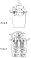
- Regulating arms 19, 20 are fixed to the first and second shafts of swing 12, 13 at ends thereof, respectively.
- Operating levers 23, 24 are attached to the regulating arms 19, 20 through mounting plates 21, 22, respectively. As shown in Figs.
- a pair of projections 25, 25 are integrally provided at the right and left of the regulating arms 19, 20.
- a base 26 for the case 8 is fixed on the top surface of the main body 1 of the valve. Screws 27, 27 serving as stoppers are screwed into the base 26 and then secured with lock nuts 28, 28.
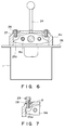
- Fig. 5 showing a second embodiment of the present invention is part of a view corresponding to Fig. 2 showing the first embodiment.
- the second embodiment is the same as the first embodiment except that a hexagon headed bolt 29 is used in place of the screw 27 in Fig. 2, with a lock nut 28 screwed thereto at the bottom surface of the base 26 for securing it.
- Fig. 6 showing a third embodiment of the present invention corresponds to Fig. 2 showing the first embodiment.
- the screw 27 is screwed into a case 8a at the top surface thereof and is secured by the lock nut 28.
- a projection 25a of a regulating arm 19a comes in contact with an end of the screw 27, thereby regulating a control input of the first operating lever 23.
- a swing magnitude of the first regulating arm 19a is limited accordingly with a resultant limitation on a swing magnitude of the first actuating arm 17.
- a maximum pilot pressure outputted from the output port 5 can be limited accordingly.
- Fig. 7 showing a fourth embodiment of the present invention is part of a view corresponding to Fig.
- FIG. 6 The corresponding view is the same as Fig. 6 except that the hexagon headed bolt 29 is used in place of the screw 27 in Fig. 6, with the lock nut 28 screwed thereto for securing it.
- Fig. 8 showing a fifth embodiment of the present invention corresponds to Fig. 2.
- the screw 27 screwed into a projection 25b of a regulating arm 19b is secured by the lock nut 28.
- An end of the screw 27 comes in contact with the base 26 of the case 8, thereby regulating a control input of the first operating lever 23.
- Fig. 9 showing a sixth embodiment of the present invention is part of a view corresponding to Fig. 8.
- the corresponding view is the same as Fig. 8 except that the hexagon headed bolt 29.
- Fig. 8 the hexagon headed bolt 29 is used in place of the screw 27 in Fig. 6, with the lock nut 28 screwed thereto for securing it.
- Fig. 8 showing a fifth embodiment of the present invention corresponds to Fig. 2.
- FIG. 10 showing a seventh embodiment of the present invention corresponds to Fig. 9.
- Fig. 10 is the same as Fig. 9 except that the lock nut 28 is screwed onto the screw 27 at the top surface of the projection 25b of the regulating arm 19b for securing the screw 27.
- Fig. 11 showing an eighth embodiment of the present invention corresponds to Fig. 9 .
- Fig. 11 is the same as Fig. 9 except that the hexagon head portion of the hexagon headed bolt 29 of Fig. 9 is brought in contact with the base 26 of the case 8 to regulate a control input of the first operating lever 23.
- the above description of the first through eighth embodiments has only covered operations associated with the first operating lever 23.
- the second operating lever 24 is similar in operations to the first operating lever 23, and hence the description of operations thereof is omitted.
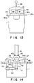
- Figs. 12 and 13 showing a ninth embodiment of the present invention correspond to Figs. 1 and 2, respectively. Parts used in common with Figs. 1 and 2 are denoted by common reference numerals, and the description thereof is omitted.
- a first stopper arm 30 is fitted to the first shaft of swing at an outer end thereof.
- the first operating lever 23 is fixed to the first mounting plate 21, which, in turn, is securely fixed to the first stopper arm 30 by two bolts 32, 32.
- a second stopper arm 31 is fitted to the second shaft of swing at an outer end thereof, and the second operating lever 24 is fixed to the second mounting plate 22, which, in turn, is securely fixed to the second stopper arm 31 by two bolts 32, 32.
- Slant bottom faces 30a, 30b of the first stopper arm 30 are respectively brought in contact with a top surface 26a of the base 26, thus forming stopper portions to regulate a control input of the first operating lever 23.
- slant bottom faces 31a, 31b, not shown, of the second stopper arm 31 are respectively brought in contact with the top surface 26a of the base 26, thus forming stopper portions to regulate a control input of the second operating lever 24.
- the first stopper arm 30 swings through the two bolts 32, 32 of the first mounting plate 21 until either of the slant bottom faces 30a, 30b comes in contact with the top surface 26a of the base 26. With either of the slant bottom faces 30a, 30b of the first stopper arm 30 being in contact with the top surface 26a of the base 26, at an attempt to further swing the first operating lever 23, the operating force of the first operating lever 23 is transmitted to the base 26 through the first mounting plate 21 and the first stopper arm 30 fixed securely thereto by the two bolts 32, 32, with no torque acting on the first shaft of swing 12. As a result, no over-force acts on a pin bolt 29, shown in Figs.
- first stopper arm 30 can be connected to the first shaft of swing 12 at an outer end thereof before assembling the hydraulic pilot valve, they can be connected by welding or be formed into an integral part. This significantly increases a connecting strength between the first shaft of swing 12 and the first stopper arm 30.
- first stopper arm 30 also serves as a mounting flange for the first operating lever 23, it allows the first mounting plate 21, which is an integral part of the first operating lever 23, to be mounted thereto with ease and securely by the bolts 32, 32.
- second operating lever 24, the second stopper arm 31, and the second mounting plate 22 are denoted by common reference numerals, and the description thereof is omitted.
- a pair of supporting brackets 44a, 44b and an intermediate bracket 45 are spaced apart and formed integrally on the base 46 located on the top surface of the main body 1 of the valve.
- Cutout windows 52, 52 are formed between the supporting brackets 44a, 44b and the intermediate bracket 45 above the top surface of the main body 1 of the valve so as to open upon a recess 1a.
- a shaft 53 extends through a pair of the supporting brackets 44a, 44b and the intermediate bracket 45.
- a pair of actuating arms 47, 48 are pivotally mounted on the shaft 53 at their longitudinal center portions. Both longitudinal ends of the actuating arms 47, 48 are in contact with top ends of the spools 3 shown in Figs. 1-4.
- Substantially ⁇ -shaped damper mechanism mounting brackets 47a, 48a extend downward from the longitudinal center portions of the actuating arms 47, 48, respectively.
- damper mechanism mounting brackets 47a, 48a project off the sides of the main body 1 of the valve through the cutout windows 52, 52 and the recess 1a.
- a damper mechanism 50 is pivotally mounted between the damper mechanism mounting bracket 47a and a bracket 49 fixed on the side surface of the main body 1 of the valve.
- another damper mechanism 51 is pivotally mounted to the other damper mechanism mounting bracket 48a.
- operating lever mounting brackets 41, 42 are fixed to the top surfaces of the actuating arms 47, 48 at the longitudinal center portions thereof, respectively, by bolts 43, 43.
- the actuating arm 47 presses the spool 3 down to feed hydraulic pilot oil, and also the damper mechanism mounting bracket 47a swings and causes the damper mechanism to expand or contract. Even when there arises a potential erroneous movement of the first operating lever 23 due to an inertial force of the first operating lever 23 caused by vibrations of a vehicle body or the like, an operating force caused by the inertial force is damped by the damper mechanism 50, thereby preventing the first operating lever 23 from operating erroneously.
- the damper mechanism mounting bracket 47a is formed integrally with the actuating arm 47, and the damper mechanism 50 is connected between the damper mechanism mounting bracket 47a and the side surface of the main body 1 of the valve.
- the damper mechanism 50 is mounted on the hydraulic pilot valve itself, the damper mechanism 50 is attached concurrently with the assembly of the hydraulic pilot valve, thus reducing man-hours of assembly.
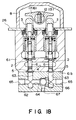
- Fig. 18 showing an eleventh embodiment of the present invention parts used in common with Figs. 1-4 are denoted by common reference numerals, and the description thereof is omitted.
- a valve block 62 is fixed to a main body 61 of a valve at a bottom surface 61b thereof where output ports 5, 5 open upon the outside, using bolts, not shown, or the like.
- a plurality of passages 63, 63 communicating with the output ports 5, 5 and a communicating passage 64 for communicating a plurality of the passages 63, 63 with each other are formed in the valve block 62.
- Output ports 65, 65 open upon the outside at both ends of the communicating passage 64.
- a shuttle valve including a ball 66 is formed in the communicating passage 64 between a plurality of the passages 63, 63.
- a higher one of pilot pressures of a plurality of the passages 63, 63 is taken out from a maximum pressure output port 67.
- the second operating lever 24 is similar in operations to the first operating lever 23, and hence the description of operations thereof is omitted. Swinging the first operating lever 23 causes the actuating arm 47 to press the spool 3 down. A higher one of pilot pressures fed from the output ports 5, 5 to the communicating passage 64 through a plurality of passages 63, 63 presses the ball 66 to be taken out from the maximum pressure output port 67. Also, respective pilot pressures can be taken out from the output ports 65, 65 communicating with a plurality of the passages 63, 63.
- the present invention is effective to serve as a hydraulic pilot valve to execute a directional changeover on control valves or the like feeding hydraulic oil to cylinders for driving a working unit mounted on construction machinery such as hydraulic excavators, wheel-mounted loaders, dump trucks, bulldozers and the like.
Landscapes
- Engineering & Computer Science (AREA)
- General Engineering & Computer Science (AREA)
- Mining & Mineral Resources (AREA)
- Civil Engineering (AREA)
- Structural Engineering (AREA)
- Physics & Mathematics (AREA)
- Fluid Mechanics (AREA)
- Mechanical Engineering (AREA)
- Operation Control Of Excavators (AREA)
- Mechanically-Actuated Valves (AREA)
Applications Claiming Priority (1)
| Application Number | Priority Date | Filing Date | Title |
|---|---|---|---|
| PCT/JP1992/001318 WO1994009278A1 (fr) | 1992-10-09 | 1992-10-09 | Soupape pilote hydraulique |
Publications (4)
| Publication Number | Publication Date |
|---|---|
| EP0775832A3 EP0775832A3 (fr) | 1994-04-28 |
| EP0775832A2 true EP0775832A2 (fr) | 1997-05-28 |
| EP0775832A1 EP0775832A1 (fr) | 1997-05-28 |
| EP0775832A4 EP0775832A4 (fr) | 1998-02-25 |
Family
ID=14042600
Family Applications (1)
| Application Number | Title | Priority Date | Filing Date |
|---|---|---|---|
| EP94913432A Withdrawn EP0775832A4 (fr) | 1992-10-09 | 1992-10-09 | Soupape pilote hydraulique |
Country Status (3)
| Country | Link |
|---|---|
| US (1) | US5558127A (fr) |
| EP (1) | EP0775832A4 (fr) |
| WO (1) | WO1994009278A1 (fr) |
Families Citing this family (13)
| Publication number | Priority date | Publication date | Assignee | Title |
|---|---|---|---|---|
| JP3503756B2 (ja) * | 1993-09-28 | 2004-03-08 | 株式会社小松製作所 | 油圧パイロット弁のダンパ装置 |
| JPH08159331A (ja) * | 1994-12-08 | 1996-06-21 | Komatsu Ltd | 油圧パイロット弁 |
| US5940997A (en) * | 1997-09-05 | 1999-08-24 | Hitachi Construction Machinery Co., Ltd. | Hydraulic circuit system for hydraulic working machine |
| US6073904A (en) * | 1997-10-02 | 2000-06-13 | Diller; Ronald G. | Latching coil valve |
| DE19961052A1 (de) * | 1999-12-16 | 2001-07-26 | Sauer Danfoss Gmbh | Steuervorrichtung für die manuell- oder fußgeführte Steuerung von Arbeitsmaschinen |
| US6394431B1 (en) * | 2001-03-21 | 2002-05-28 | Caterpillar Inc. | High force feel bumper with low final load |
| FR2846719B1 (fr) * | 2002-10-31 | 2006-02-03 | Mannesmann Rexroth Sa | Distributeur de fluide sous pression a armature suspendue |
| KR200384604Y1 (ko) * | 2005-02-01 | 2005-05-17 | 김태조 | 안경형 배관파이프 개폐 분리구 |
| US7967024B2 (en) * | 2008-03-14 | 2011-06-28 | Clark Equipment Company | Hydraulic valve assembly with valve locking mechanism |
| JP5238739B2 (ja) * | 2010-02-26 | 2013-07-17 | 川崎重工業株式会社 | 操作装置 |
| DE202011104220U1 (de) * | 2011-08-10 | 2012-12-14 | Viega Gmbh & Co. Kg | Manuell zu betätigendes Servoventil, insbesondere zur Druckspülung eines Urinals |
| FR3042574B1 (fr) * | 2015-10-19 | 2018-05-04 | Robert Bosch Gmbh | Distributeur de liquide hydraulique sous une pression commandee |
| WO2022163294A1 (fr) * | 2021-01-27 | 2022-08-04 | 株式会社クボタ | Mécanisme de direction et engin de chantier |
Family Cites Families (19)
| Publication number | Priority date | Publication date | Assignee | Title |
|---|---|---|---|---|
| US3800615A (en) * | 1972-06-14 | 1974-04-02 | Ware Machine Works Inc | Single lever control mechanism |
| JPS5222126B2 (fr) * | 1973-03-31 | 1977-06-15 | ||
| JPS551971Y2 (fr) * | 1973-12-20 | 1980-01-19 | ||
| JPS544089A (en) * | 1977-06-10 | 1979-01-12 | Shigeru Obiyama | Xxray generator |
| US4296773A (en) * | 1979-02-12 | 1981-10-27 | Walter Kidde & Company, Inc. | Hydraulic selector valve having joy stick control |
| BR8009083A (pt) * | 1980-06-16 | 1982-04-27 | Caterpillar Tractor Co | Valvula de reducao de pressao para abaixamento do ponto morto do motor |
| DE3634887A1 (de) * | 1986-10-14 | 1988-04-21 | Bayer Ag | 2-(5-oxo-2-imidazolin-2-yl)-pyridin-derivate |
| JPH0332869Y2 (fr) * | 1986-12-22 | 1991-07-11 | ||
| EP0316480B1 (fr) * | 1987-11-20 | 1994-02-16 | Deutsche ITT Industries GmbH | Amplificateur de puissance à large bande intégré monolithiquement |
| JPH07103942B2 (ja) * | 1988-03-31 | 1995-11-08 | 株式会社小松製作所 | 油圧パイロットバルブ装置 |
| DE69012294T2 (de) * | 1989-04-28 | 1995-05-04 | Kabushiki Kaisha Komatsu Seisakusho, Tokio/Tokyo | Pilotventil. |
| JPH03105701A (ja) * | 1989-09-19 | 1991-05-02 | Matsushita Electric Ind Co Ltd | ビデオテープレコーダ |
| JPH03105787A (ja) * | 1989-09-19 | 1991-05-02 | Nec Ic Microcomput Syst Ltd | 半導体集積回路 |
| US4926905A (en) * | 1989-09-29 | 1990-05-22 | Williams Controls, Inc. | Manually operated air valve and actuator in combination control a hydraulic spool valve for maneuvering heavy equipment |
| JPH03105787U (fr) * | 1990-02-19 | 1991-11-01 | ||
| JPH0644646B2 (ja) * | 1990-05-16 | 1994-06-08 | 住友金属鉱山株式会社 | 固体レーザ素子体の表面の清浄化方法 |
| JPH04129989A (ja) * | 1990-09-19 | 1992-04-30 | Toshiba Corp | エレベータドア |
| JPH0588791A (ja) * | 1991-04-10 | 1993-04-09 | Internatl Business Mach Corp <Ibm> | マイクロコンピユータ、不在時動作方法及びオプシヨン・カード |
| FR2699249B1 (fr) * | 1992-12-15 | 1995-03-10 | Rexroth Sigma | Dispositif distributeur de fluide hydraulique pour télécommande hydraulique et cartouche de régulation modulaire pour un tel dispositif . |
-
1992
- 1992-10-09 US US08/416,699 patent/US5558127A/en not_active Expired - Fee Related
- 1992-10-09 EP EP94913432A patent/EP0775832A4/fr not_active Withdrawn
- 1992-10-09 WO PCT/JP1992/001318 patent/WO1994009278A1/fr not_active Ceased
Also Published As
| Publication number | Publication date |
|---|---|
| US5558127A (en) | 1996-09-24 |
| EP0775832A4 (fr) | 1998-02-25 |
| WO1994009278A1 (fr) | 1994-04-28 |
Similar Documents
| Publication | Publication Date | Title |
|---|---|---|
| EP0775832A2 (fr) | Soupape pilote hydraulique | |
| EP0775832A1 (fr) | Soupape pilote hydraulique | |
| US5533334A (en) | Pressurized fluid supply system | |
| US6435289B1 (en) | Apparatus for altering operation apparatus and actuator combinations, and operation lever apparatus | |
| KR19990030251A (ko) | 유압식 스티어링 장치 및 그 유압밸브 | |
| EP0716235B1 (fr) | Vanne à commande hydraulique | |
| JP2551538Y2 (ja) | パイロット弁 | |
| JP3380074B2 (ja) | 建設機械の操作システム | |
| US4041976A (en) | Single lever control arrangement for actuating multiple valves | |
| US5317953A (en) | Neutral-centering valve control system | |
| US4064766A (en) | Modular control linkage assembly for a hydrostatic transmission | |
| JPH0214224B2 (fr) | ||
| US6907902B2 (en) | Hydraulic signal output device | |
| US4953917A (en) | Steering-brake system | |
| JPH0242289A (ja) | 安全弁 | |
| AU2020231065B2 (en) | Electro-hydraulic arrangement for an earthmoving machine | |
| JPH0526064B2 (fr) | ||
| JP2581829Y2 (ja) | 変速装置用の流体圧式アクチュエータユニット | |
| EP0753668B1 (fr) | Amortisseur pour servo-soupape hydraulique | |
| JPH0743526Y2 (ja) | 車両の変速操作装置 | |
| JP2582656Y2 (ja) | 油圧パイロット弁 | |
| JP2001125657A (ja) | 操作レバー装置 | |
| JPS5841365Y2 (ja) | 倍力装置 | |
| JPH0625751Y2 (ja) | パイロットアクチュエート式選択バルブ | |
| JPH0526323Y2 (fr) |
Legal Events
| Date | Code | Title | Description |
|---|---|---|---|
| PUAI | Public reference made under article 153(3) epc to a published international application that has entered the european phase |
Free format text: ORIGINAL CODE: 0009012 |
|
| 17P | Request for examination filed |
Effective date: 19950322 |
|
| AK | Designated contracting states |
Kind code of ref document: A2 Designated state(s): DE GB |
|
| PUAK | Availability of information related to the publication of the international search report |
Free format text: ORIGINAL CODE: 0009015 |
|
| AK | Designated contracting states |
Kind code of ref document: A3 Designated state(s): DE GB |
|
| K1C1 | Correction of patent application (title page) published |
Effective date: 19970528 |
|
| A4 | Supplementary search report drawn up and despatched | ||
| AK | Designated contracting states |
Kind code of ref document: A4 Designated state(s): DE GB |
|
| PUAF | Information related to the publication of a search report (a3 document) modified or deleted |
Free format text: ORIGINAL CODE: 0009199SEPU |
|
| D17D | Deferred search report published (deleted) | ||
| 17Q | First examination report despatched |
Effective date: 19990906 |
|
| STAA | Information on the status of an ep patent application or granted ep patent |
Free format text: STATUS: THE APPLICATION HAS BEEN WITHDRAWN |
|
| 18W | Application withdrawn |
Withdrawal date: 19991103 |