EP0776109A2 - Filtre de réception pour signaux à modulation d'impulsions - Google Patents
Filtre de réception pour signaux à modulation d'impulsions Download PDFInfo
- Publication number
- EP0776109A2 EP0776109A2 EP96307942A EP96307942A EP0776109A2 EP 0776109 A2 EP0776109 A2 EP 0776109A2 EP 96307942 A EP96307942 A EP 96307942A EP 96307942 A EP96307942 A EP 96307942A EP 0776109 A2 EP0776109 A2 EP 0776109A2
- Authority
- EP
- European Patent Office
- Prior art keywords
- filter
- signal
- pulse
- frequency
- gain
- Prior art date
- Legal status (The legal status is an assumption and is not a legal conclusion. Google has not performed a legal analysis and makes no representation as to the accuracy of the status listed.)
- Withdrawn
Links
- 230000015556 catabolic process Effects 0.000 claims description 5
- 238000006731 degradation reaction Methods 0.000 claims description 5
- 238000001914 filtration Methods 0.000 claims description 3
- 230000000116 mitigating effect Effects 0.000 claims description 2
- 238000000034 method Methods 0.000 abstract description 6
- 230000002708 enhancing effect Effects 0.000 abstract description 2
- 230000000694 effects Effects 0.000 description 14
- 230000001965 increasing effect Effects 0.000 description 7
- 230000001066 destructive effect Effects 0.000 description 3
- 238000010586 diagram Methods 0.000 description 3
- 238000006243 chemical reaction Methods 0.000 description 2
- 238000012545 processing Methods 0.000 description 2
- 238000010897 surface acoustic wave method Methods 0.000 description 2
- 230000018199 S phase Effects 0.000 description 1
- 238000013459 approach Methods 0.000 description 1
- 230000003247 decreasing effect Effects 0.000 description 1
- 230000001934 delay Effects 0.000 description 1
- 238000013461 design Methods 0.000 description 1
- 238000005516 engineering process Methods 0.000 description 1
- 230000002452 interceptive effect Effects 0.000 description 1
- 238000012986 modification Methods 0.000 description 1
- 230000004048 modification Effects 0.000 description 1
- 238000005070 sampling Methods 0.000 description 1
- 238000004088 simulation Methods 0.000 description 1
Images


Classifications
-
- H—ELECTRICITY
- H04—ELECTRIC COMMUNICATION TECHNIQUE
- H04L—TRANSMISSION OF DIGITAL INFORMATION, e.g. TELEGRAPHIC COMMUNICATION
- H04L25/00—Baseband systems
- H04L25/02—Details ; arrangements for supplying electrical power along data transmission lines
- H04L25/03—Shaping networks in transmitter or receiver, e.g. adaptive shaping networks
- H04L25/03006—Arrangements for removing intersymbol interference
Definitions
- Pulse modulated signals are signals in which some perameter of a pulse train is varied in accordance with data.
- a received signal is demodulated to extract a pulse modulated signal.
- the pulses of the pulse modulated signal represent symbols by means of which the message data are encoded. These symbols have to be decoded to determine the underlying message data.
- a postdetection filter for filtering the pulse modulated signal that is input to that section, for example to remove high frequency noise, and a decoder for decoding the signal that is output from the filter.
- the signal input to the postdetection filter has typically suffered already from degradation. This arises from noise, co-channel interference, intersymbol interference (ISI) and distortion from components earlier in the receiver circuit. Therefore, postdetection filters are normally selected to minimise any further degradation.
- the postdetection filter is usually chosen to be a Bessel filter or a Butterworth filter because these have a generally linear phase response, which leads to little distortion of the pulses in the signal output from the filter, and frequency responses of increasing loss at increasing frequency, which is felt to remove as much noise as possible.
- Figure 1 illustrates at 1 the frequency response of a typical Bessel filter.
- Figure 2 illustrates at 2 the phase response of a typical Bessel filter as a plot of relative group delay against frequency. Because the pulse modulated signal is degraded, techniques such as DFE (decision feedback equalisation) and Viterbi decoding are used in the decoder to increase the likelihood of correctly decoding the signal output from the postdetection filter.
- DFE decision feedback equalisation
- Viterbi decoding are used in the decoder to increase the likelihood of correctly decoding the signal output from the postdetection filter.
- a signal receiver comprising a filter for receiving a pulse modulated signal and filtering it to generate a second signal, the filter having a greater gain at half the pulse frequency of the pulse modulated signal than at a lower frequency.
- the lower frequency is suitably, for example, zero (DC) or a quarter or a sixth of the pulse frequency.
- the filter has a substantially greater gain at half the pulse frequency than at the lower frequency.
- the filter's gain is 1 to 5 dB greater at half the pulse frequency than at the lower frequency, more preferably 1.5 to 2.5 dB greater, most preferably around 2 dB greater.
- the filter has a greater gain at half the pulse frequency than at any frequency lower than that.
- the gain of the filter peaks around, most preferably at or substantially at, half the pulse frequency.
- the gain of the filter preferably peaks at between 0.25 and 0.75 times the pulse frequency, more preferably within 25% of half the pulse frequency, most preferably within 10% of half the pulse frequency.
- the filter has an absolute gain at half the pulse frequency.
- One effect of the filter, and especially its gain characteristics, is suitably to mitigate the effect of ISI in the said pulse modulated signal, suitably by enhancing in the second signal components of the said pulse modulated signal at half the pulse frequency relative to components at the said lower frequency.
- the receiver suitably comprises a demodulating means for demodulating a received signal to produce the pulse modulated signal.
- the filter is suitably arranged to receive that pulse modulated signal.
- the receiver suitably comprises a decoder for decoding a signal dependant on the second signal, most preferably for decoding the second signal itself.
- the decoder suitably decodes the signal by sampling it at at least the pulse frequency, preferably at the pulse frequency.
- the decoder preferably receives the second signal directly from the filter. Alternatively there may be some processing of the signal between the filter and the decoder.
- the filter is suitably in the baseband section of the receiver. It is suitably a postdetection filter, suitably in a radio signal receiver of a radio telephone.
- the radio telephone 3 has a receiving section 4 which receives signals and decodes them for processing by processor 5.
- the receiving section comprises an antenna 6, a bandpass filter 7 (for example a SAW (surface acoustic wave) filter), a demodulator 8 and a baseband section 4a comprising a postdetection filter 9 and a decoder 10.
- the telephone comprises a microphone 23, a speaker 24 a keypad 25 and a transmit section 26 to allow telephone calls to be made.
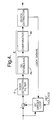
- Figure 4 shows in more detail that the analogue to digital conversion circuit of the telephone comprises a DC offset circuit; the postdetection filter 9; a deinterleaving circuit 8a and a comparator 8b in the decoder 8; and a clock extractor which generates a lock signal.
- the radio telephone is a DECT (digital European cordless technology) handset.
- GFSK Gausian frequency shift keying
- the signal received by baseband section 4a is a PCM (pulse code modulated) signal.
- the PCM signal is a pulse modulated signal made up of regular pulses at a frequency of 1.152 MHz. The amplitude of each pulse is dependant on the symbol it represents and on the degradation the signal has suffered, including degradation due to ISI.
- Figure 5 illustrates a typical PCM signal at the input 11 to the postdetection filter.
- the signal is a pulse code modulated signal using a binary code with positive (+1) and negative (-1) pulses. Each pulse represents a symbol. Because the support of each pulse exceeds the bit period of the signal each pulse is affected by ISI from adjacent pulses. For instance, in figure 5 destructive interference from adjacent +1 pulses 13 and 14 has reduced the amplitude of -1 pulse 12. At 15 three adjacent +1 pulses have interfered constructively to cause increased amplitude. This increased amplitude together with +1 pulse 16 has reduced greatly, by destructive interference, the amplitude of -1 pulse 17. Pulses of reduced amplitude are at particular risk of being decoded wrongly by decoder 10. For example, noise may easily swamp a low amplitude pulse.
- a decrease in amplitude due to destructive interference is especially likely to occur where the signs of adjacent pulses alternate (for example in a +1, -1, +1 sequence in a binary coded signal). Because they alternate in sign at the pulse frequency these sections of the input signal have a relatively strong component at half the pulse frequency. This is clear from the left-most portion of figure 5. An increase in amplitude due to constructive interference is especially likely to occur where adjacent pulses have the same sign. These sections of the input signal have a relatively strong component at lower frequencies - for example DC, or a quarter or a sixth of the pulse frequency.
- Figure 6 illustrates at 18 the frequency response of filter 9 according to the example of the present invention.
- the frequency response of the filter 9 peaks at around half the pulse frequency of the pulse modulated signal at 11 received by the filter 9. Above that peak the gain of the filter falls, to filter high frequency noise from the signal. Below the peak the gain also falls, initially at an increasing rate and then at a decreasing rate as it approaches zero frequency. The gain at zero frequency is approximately zero. The effect of this is that in the second signal (at 19) output from the filter the components of the signal at 11 at half the pulse frequency are enhanced relative to components of lower frequencies.
- the filter 9 has an absolute gain at half the pulse frequency, but this is not essential. It is preferred for the gain of the filter to peak within 20%, 10% or 5% of half the pulse frequency.
- the filter is not restricted to binary coded signals - it may benefit pulse modulated signals that have more than two possible symbols.
- figure 2 illustrates the relative group delay of filter 9. This characteristic is not as linear as that of the Bessel filter.
- One way to reduce any non-linearity in group delay is by using a delay equaliser.
- FIG. 7 shows the filter 9 in more detail.
- filter which could be used is a biquad circuit.
- the quality factor Q of such a filter would suitably be from around 1 to around 1.5.
- Figure 8 illustrates the effect of the filter 9 on a pulse modulated signal.
- Signal 21 (indicated by a heavy line) is the pulse modulated signal at the input 11 to the filter.
- Signal 22 (indicated by a light line) is the pulse modulated signal at the output 19 of the filter. It can be seen that the amplitudes of the pulses have been to some extent equalised in the output signal and so the effect of ISI has been mitigated.
- the decoder 8 may use techniques such as DFE (decision feedback equalisation) and Viterbi decoding to increase further the likelihood of correctly decoding the signal output from the postdetection filter.
- the precise characteristics of the filter are chosen with the aim of maximising the probability that the pulse modulated signal will be decoded correctly. To achieve this it may be necessary to balance the effects of more than one of the filter's characteristics. For instance, especially in a lower order filter, the effect of the filter's gain characteristics in reducing ISI may have to be balanced against distortion introduced by any non-linearity of the filter's phase response. A rough estimate of the required gain may be made by noting that (in a binary coded signal) equalising as far as possible the amplitudes of the pulses in the signal will go a long way to mitigating the effect of ISI.
- a first approximation of the desired gain of the filter may be made by measuring the amplitudes of high and low amplitude pulses such as 15 and 17 in figure 5 and then taking the required gain of the filter to be h 1 /h 2 , where h 1 is the amplitude of pulse 15 and h 2 is the amplitude of pulse 17.
- the pulses whose amplitudes are measured may be merely a simulation of the pulse modulated signal.
- this relative gain is unlikely to equalise the amplitudes exactly because even pulses such as pulse 15 contain some components near half the pulse frequency.
- a more precise judgement of the preferred characteristics may therefore be made by an optimising process in which the characteristics of a given order of filter are varied, and the effect of this on the probability of a simulated pulse modulated signal being decoded correctly is monitored.
- the ISI caused by any pulse may, in most cases, be considered to be limited to the three or four adjacent pulses on either side of that pulse.
- the gain of the filter at half the pulse frequency will be between 1 dB and 5 dB greater than the gain at zero frequency. In figure 6 the figure is around 2 dB.
- the filter 9 also has the potential to reduce the effects of other sources of distortion of the signal.
- the strongest interfering signals due to co-channel interference are likely to be those in which pulses have constructively interfered with each other. Those are likely to be sections of consecutive pulses of the same sign which contain a relatively strong low frequency component and are therefore selectively filtered from the signal at 11 by the filter 9.
- the other filters in the receiver conventionally have increasing loss at increasing frequency, and therefore greater loss at half the pulse frequency than at lower frequencies. These filters can increase ISI but this effect can to some extent be reversed by the filter 9.
- the filter 9 has been found to be most effective when it is located in the baseband section of the receiver and immediately before the decoder so that the decoder takes as input the signal output from the filter. However, this is not essential.
- the filter may be advantageous in the RF section of the receiver and even if there are components of the receiver between the filter and the decoder. In that case the decoder would take as input a signal generated in dependence on the signal output from the filter.
Landscapes
- Engineering & Computer Science (AREA)
- Power Engineering (AREA)
- Computer Networks & Wireless Communication (AREA)
- Signal Processing (AREA)
- Noise Elimination (AREA)
- Networks Using Active Elements (AREA)
- Digital Transmission Methods That Use Modulated Carrier Waves (AREA)
- Dc Digital Transmission (AREA)
Applications Claiming Priority (2)
| Application Number | Priority Date | Filing Date | Title |
|---|---|---|---|
| GB9524094A GB2307626B (en) | 1995-11-24 | 1995-11-24 | A signal receiver |
| GB9524094 | 1995-11-24 |
Publications (2)
| Publication Number | Publication Date |
|---|---|
| EP0776109A2 true EP0776109A2 (fr) | 1997-05-28 |
| EP0776109A3 EP0776109A3 (fr) | 2000-08-30 |
Family
ID=10784425
Family Applications (1)
| Application Number | Title | Priority Date | Filing Date |
|---|---|---|---|
| EP96307942A Withdrawn EP0776109A3 (fr) | 1995-11-24 | 1996-11-01 | Filtre de réception pour signaux à modulation d'impulsions |
Country Status (4)
| Country | Link |
|---|---|
| US (1) | US5960043A (fr) |
| EP (1) | EP0776109A3 (fr) |
| JP (1) | JPH09219725A (fr) |
| GB (1) | GB2307626B (fr) |
Families Citing this family (2)
| Publication number | Priority date | Publication date | Assignee | Title |
|---|---|---|---|---|
| US6097964A (en) | 1997-09-04 | 2000-08-01 | Nokia Mobile Phones Limited | Navigation key for a handset |
| WO2001001570A1 (fr) * | 1999-06-25 | 2001-01-04 | Infineon Technologies Ag | Filtre passe-bande programmable pour un circuit codec |
Family Cites Families (9)
| Publication number | Priority date | Publication date | Assignee | Title |
|---|---|---|---|---|
| US3924068A (en) * | 1973-12-27 | 1975-12-02 | Nasa | Low distortion receiver for bi-level baseband PCM waveforms |
| FR2422291A1 (fr) * | 1978-04-07 | 1979-11-02 | Cit Alcatel | Filtre passe-bas pour bande telephonique |
| JPH0619904B2 (ja) * | 1983-05-20 | 1994-03-16 | 日本ビクター株式会社 | デジタル信号の波形処理方式 |
| US4652835A (en) * | 1984-08-27 | 1987-03-24 | Hewlett-Packard Company | Gain control bandpass LCR filter with variable bandwidth |
| GB8507903D0 (en) * | 1985-03-26 | 1985-05-01 | Tomlinson M | Noise-reduction signal processing arrangement |
| US4713627A (en) * | 1986-10-10 | 1987-12-15 | Tektronix, Inc. | Active filter with bootstrapping |
| JP2860419B2 (ja) * | 1991-04-29 | 1999-02-24 | モトローラ・インコーポレーテッド | 干渉レベルを検出しかつ指示する回路および方法 |
| EP0579876B1 (fr) * | 1992-07-24 | 1998-09-02 | Alcatel | Système pour l'accord de fréquences pour une pair d'amplificateurs opérationnels à transconductance-C |
| JPH0927722A (ja) * | 1995-07-12 | 1997-01-28 | Fuji Xerox Co Ltd | ゲイン可変増幅装置 |
-
1995
- 1995-11-24 GB GB9524094A patent/GB2307626B/en not_active Expired - Lifetime
-
1996
- 1996-11-01 EP EP96307942A patent/EP0776109A3/fr not_active Withdrawn
- 1996-11-19 JP JP8307999A patent/JPH09219725A/ja active Pending
- 1996-11-20 US US08/754,220 patent/US5960043A/en not_active Expired - Lifetime
Non-Patent Citations (1)
| Title |
|---|
| None |
Also Published As
| Publication number | Publication date |
|---|---|
| US5960043A (en) | 1999-09-28 |
| GB2307626A (en) | 1997-05-28 |
| EP0776109A3 (fr) | 2000-08-30 |
| GB9524094D0 (en) | 1996-01-24 |
| GB2307626B (en) | 2000-06-07 |
| JPH09219725A (ja) | 1997-08-19 |
Similar Documents
| Publication | Publication Date | Title |
|---|---|---|
| KR970007362B1 (ko) | 수신기에서의 손상된 신호 등화 장치 및 방법 | |
| JP2591343B2 (ja) | チャンネル等化によるソフト判定復号方法 | |
| TW393839B (en) | A transmission system for digital audio broadcasting | |
| US4523311A (en) | Simultaneous transmission of speech and data over an analog channel | |
| JPH08107367A (ja) | 高周波受信信号における帯域内干渉を低減させる装置 | |
| US7212593B2 (en) | Method of and apparatus for noise whitening filtering | |
| EP0731567B1 (fr) | Estimateur pour évaluer la séquence de la probabilité maximale et procédé pour la mise en oeuvre | |
| WO2002009297A2 (fr) | Procede de selection de sequence de voies et d'estimation de voies dans un systeme de communication sans fil | |
| US6389572B1 (en) | Method of extracting bits from modulated waveforms | |
| GB2250667A (en) | An apparatus and method for removing distortion in a received signal | |
| US6704353B1 (en) | Method and apparatus for tracking the magnitude of channel induced distortion to a transmitted signal | |
| US5960043A (en) | Signal receiver | |
| KR100337020B1 (ko) | 동일채널에서동작하는신호들을분리하기위한방법및장치 | |
| JP2003502910A (ja) | 徐々に変化するディスターバンスがある場合のバイナリ情報検出のための方法とシステム | |
| WO2006102315A2 (fr) | Systeme et procede de communication de donnees avec signal egalise a amplitude constante | |
| US6266521B1 (en) | Receiver and method for demodulating reception signals | |
| WO2001020841A1 (fr) | Technique de demodulation d'un signal de donnees module lineaire dans un systeme de communication | |
| US5784416A (en) | Method and apparatus for detection of a communication signal | |
| CN1337096A (zh) | 涉及多相接收机的改进方案 | |
| US6952445B2 (en) | Symbol constellations having second-order statistics with cyclostationary phase | |
| JPH04360441A (ja) | 干渉補償方式 | |
| KR100379380B1 (ko) | 통신 시스템에서 간섭신호 제거 방법 | |
| JPH09130442A (ja) | π/4シフトQPSK復調器 | |
| Heath et al. | Assessment of linear modulation techniques and their application to personal radio communications systems | |
| Bruckmann et al. | A CPFSK/PSK-phase reconstruction-receiver for enhanced data rate Bluetooth systems |
Legal Events
| Date | Code | Title | Description |
|---|---|---|---|
| PUAI | Public reference made under article 153(3) epc to a published international application that has entered the european phase |
Free format text: ORIGINAL CODE: 0009012 |
|
| AK | Designated contracting states |
Kind code of ref document: A2 Designated state(s): DE FR GB SE |
|
| PUAL | Search report despatched |
Free format text: ORIGINAL CODE: 0009013 |
|
| AK | Designated contracting states |
Kind code of ref document: A3 Designated state(s): DE FR GB SE |
|
| 17P | Request for examination filed |
Effective date: 20010228 |
|
| 17Q | First examination report despatched |
Effective date: 20010430 |
|
| STAA | Information on the status of an ep patent application or granted ep patent |
Free format text: STATUS: THE APPLICATION IS DEEMED TO BE WITHDRAWN |
|
| RAP1 | Party data changed (applicant data changed or rights of an application transferred) |
Owner name: NOKIA CORPORATION |
|
| 18D | Application deemed to be withdrawn |
Effective date: 20010911 |