EP0776792B1 - Structure d'absorption d'energie d'impact pour l'interieur d'un vehicule - Google Patents
Structure d'absorption d'energie d'impact pour l'interieur d'un vehicule Download PDFInfo
- Publication number
- EP0776792B1 EP0776792B1 EP95929218A EP95929218A EP0776792B1 EP 0776792 B1 EP0776792 B1 EP 0776792B1 EP 95929218 A EP95929218 A EP 95929218A EP 95929218 A EP95929218 A EP 95929218A EP 0776792 B1 EP0776792 B1 EP 0776792B1
- Authority
- EP
- European Patent Office
- Prior art keywords
- pillar
- trim
- ribs
- side edge
- impact
- Prior art date
- Legal status (The legal status is an assumption and is not a legal conclusion. Google has not performed a legal analysis and makes no representation as to the accuracy of the status listed.)
- Expired - Lifetime
Links
Images







Classifications
-
- B—PERFORMING OPERATIONS; TRANSPORTING
- B60—VEHICLES IN GENERAL
- B60R—VEHICLES, VEHICLE FITTINGS, OR VEHICLE PARTS, NOT OTHERWISE PROVIDED FOR
- B60R13/00—Elements for body-finishing, identifying, or decorating; Arrangements or adaptations for advertising purposes
- B60R13/02—Internal Trim mouldings ; Internal Ledges; Wall liners for passenger compartments; Roof liners
- B60R13/0206—Arrangements of fasteners and clips specially adapted for attaching inner vehicle liners or mouldings
-
- B—PERFORMING OPERATIONS; TRANSPORTING
- B60—VEHICLES IN GENERAL
- B60R—VEHICLES, VEHICLE FITTINGS, OR VEHICLE PARTS, NOT OTHERWISE PROVIDED FOR
- B60R13/00—Elements for body-finishing, identifying, or decorating; Arrangements or adaptations for advertising purposes
- B60R13/02—Internal Trim mouldings ; Internal Ledges; Wall liners for passenger compartments; Roof liners
- B60R13/0237—Side or rear panels
- B60R13/025—Pillars; Roof rails
-
- B—PERFORMING OPERATIONS; TRANSPORTING
- B60—VEHICLES IN GENERAL
- B60R—VEHICLES, VEHICLE FITTINGS, OR VEHICLE PARTS, NOT OTHERWISE PROVIDED FOR
- B60R21/00—Arrangements or fittings on vehicles for protecting or preventing injuries to occupants or pedestrians in case of accidents or other traffic risks
- B60R21/02—Occupant safety arrangements or fittings, e.g. crash pads
- B60R21/04—Padded linings for the vehicle interior ; Energy absorbing structures associated with padded or non-padded linings
-
- B—PERFORMING OPERATIONS; TRANSPORTING
- B60—VEHICLES IN GENERAL
- B60R—VEHICLES, VEHICLE FITTINGS, OR VEHICLE PARTS, NOT OTHERWISE PROVIDED FOR
- B60R22/00—Safety belts or body harnesses in vehicles
- B60R22/18—Anchoring devices
- B60R22/20—Anchoring devices adjustable in position, e.g. in height
- B60R22/201—Anchoring devices adjustable in position, e.g. in height with the belt anchor connected to a slider movable in a vehicle-mounted track
-
- B—PERFORMING OPERATIONS; TRANSPORTING
- B60—VEHICLES IN GENERAL
- B60R—VEHICLES, VEHICLE FITTINGS, OR VEHICLE PARTS, NOT OTHERWISE PROVIDED FOR
- B60R13/00—Elements for body-finishing, identifying, or decorating; Arrangements or adaptations for advertising purposes
- B60R13/06—Sealing strips
-
- B—PERFORMING OPERATIONS; TRANSPORTING
- B60—VEHICLES IN GENERAL
- B60R—VEHICLES, VEHICLE FITTINGS, OR VEHICLE PARTS, NOT OTHERWISE PROVIDED FOR
- B60R21/00—Arrangements or fittings on vehicles for protecting or preventing injuries to occupants or pedestrians in case of accidents or other traffic risks
- B60R21/02—Occupant safety arrangements or fittings, e.g. crash pads
- B60R21/04—Padded linings for the vehicle interior ; Energy absorbing structures associated with padded or non-padded linings
- B60R2021/0414—Padded linings for the vehicle interior ; Energy absorbing structures associated with padded or non-padded linings using energy absorbing ribs
-
- B—PERFORMING OPERATIONS; TRANSPORTING
- B60—VEHICLES IN GENERAL
- B60R—VEHICLES, VEHICLE FITTINGS, OR VEHICLE PARTS, NOT OTHERWISE PROVIDED FOR
- B60R21/00—Arrangements or fittings on vehicles for protecting or preventing injuries to occupants or pedestrians in case of accidents or other traffic risks
- B60R21/02—Occupant safety arrangements or fittings, e.g. crash pads
- B60R21/04—Padded linings for the vehicle interior ; Energy absorbing structures associated with padded or non-padded linings
- B60R2021/0435—Padded linings for the vehicle interior ; Energy absorbing structures associated with padded or non-padded linings associated with the side or roof pillars
Definitions
- This invention relates to an impact energy absorbing structure for a cabin of an automotive vehicle, which is suitable for use in absorbing impact energy of an occupant of the cabin against a pillar portion in the event of a collision or the like of the vehicle so that the occupant can be protected.
- front and rear impact absorbing structures of a vehicle body said structures permitting absorption of impact energy while the vehicle body itself is undergoing collapse, have found wide-spread utility.
- an automotive vehicle may be struck from the rear.
- an occupant is subjected to strong rearward force because of inertia force or the like.
- a head rest together with a seat back, support the back and head of the occupant so that the occupant is prevented from hitting an object located rearwards while being supported by the seat back and head rest.
- a frontal collision for example, an occupant is subjected to strong forward force due to inertia force or the like.
- a seat belt prevents forward movement of the occupant so that the occupant can avoid hitting an object located frontwards.
- forward impact energy of the occupant is absorbed in a cushioned manner by an air bag so that the occupant can avoid hitting a steering wheel, dash panel, wind shield or the like which is located frontwards.
- the occupant when force is applied to an occupant in a longitudinal direction of a vehicle body in the event of a collision, the occupant can be protected from hitting an object located frontwards or rearwards within the cabin by a seat back, a head rest, a seat belt, an air bag and/or the like as mentioned above. There is however a potential danger that the occupant may hit a side wall of the cabin when the occupant is subjected to such force as being directed toward the side wall of the cabin.
- a typical example of such a high strength and rigidity part in the side wall of the cabin is a pillar.
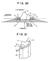
- FIG. 20 is a view showing by way of examples a test area and a range of directions of impacts in an impact absorption test which determines whether or not an impact-absorbing structure required for a pillar part to protect an occupant meets a standard.
- the drawing illustrates the testing method upon a center pillar.
- an impact absorption test is conducted in the area and directions as indicated by hatching. Namely, over an entire area of the pillar 1 ranging from a front-side flange portion 4 to a rear-side flange portion 5 where the pillar inner 2 is joined with a pillar outer 3, predetermined impact loads are applied in the corresponding directions by an object imitating an occupant to test whether or not the absorption of the impacts is sufficiently performed.
- the impact absorbing structure is determined to be free of problems insofar as, upon application of predetermined impact loads from the prescribed directions in such a range, such impacts can be absorbed before the above-described object directly reaches the pillar inner 2.
- numerals 6 and 7 in FIG. 20 indicate flange trims fitted on the flange portions 4,5, respectively.
- Typical examples of application manners of such impact loads include an impact test in which an impact is applied toward a central portion of a front wall of the pillar inner 2 from a direction a, an impact test in which impacts are applied toward a side portion of the pillar inner 2 from directions b,b' and an impact test in which impacts are applied toward the flange portions 4,5 on an edge portion of the pillar inner 2 from directions c,c'.
- trims are however intended merely to improve the cabin appearance and/or to provide better touch feeling when occupants touch pillar portions.
- conventional trims those having such a structure as shown, for example, in FIG. 21 are common. Namely, as is illustrated in FIG. 21, no particular member is arranged between the pillar inner 2 and a trim 8 to permit absorption of an impact as intended. Further, a gap d between the pillar inner 2 and the trim 8 is small so that the pillar inner 2 is caused to immediately reach the bottom upon application of an impact against the trim 8.
- Japanese Utility Model Application Laid-Open (Kokai) No. HEI 3-37040 discloses a mounting structure for a pillar garnish. This technique however is intended to permit an adjustment of a mounted position of the pillar garnish and fails to take into consideration impacts which may be applied as described above. This technique therefore cannot overcome the above-mentioned problem.
- Japanese Utility Model Application Laid-Open (Kokai) No. HEI 3-68149 discloses a mounting structure for a pillar trim. This technique is intended to protect a pillar trim from deformation. Like the technique mentioned above, nothing is however taken into consideration against impacts which may be applied to the pillar. This technique cannot overcome the above-mentioned problem either.
- a structure according to the preamble of the independent claims is known from GB-A-1053360 which discloses a protective padding arrangement suitable for use on a baggage rack in public transportation means.
- a hard body is surrounded by a padding strip.
- the hard body has a U-shaped cross-section, the limbs thereof being directed outwardly.
- Each limb is formed by undercut flanks.
- the padding strip comprises two barbed-hook-shaped marginal protections engaging in the grooves between flanks.
- a padding strip In an area around side edge portion of the hard body a padding strip comprises channel-like spaces separated by support ribs for improving the padding effect.
- the flanks extend outboardly of the hard body.
- the problem of the present invention is to provide an impact energy absorbing struture which protects an occupant by impact absorbing energy even when the ocuppant hits an inboardside of a structural member such as a pillar.
- an impact energy absorbing structure for a cabin of an automotive vehicle comprising a trim member covering an inboard side of a pillar constituting said cabin; and impact absorbing ribs arranged between an inboard side of said pillar and said trim member so that impact energy directed from a surface of said trim member toward said pillar can be absorbed, said impact absorbing ribs being formed integrally with said trim member of a resin material.
- Said trim member comprises at least one curved side edge portion covering a corresponding flange portion formed at an edge portion of said pillar, the curved side edge portion being provided inboardly relative to said flange portion. The side edge portion is also provided at a part thereof facing said corresponding flange portion with said impact absorbing ribs.
- the impact energy directed toward the pillar can be absorbed through deformation and in some instances, destruction or the like of the impact absorbing ribs so that, when the occupant in the cabin is about to hit the pillar, the impact energy can be damped to protect the occupant.
- the impact absorbing ribs and the trim member are integrally formed with the resin material. This can facilitate the absorption of the impact energy, and can also reduce the number of parts and/or components. It is also possible to produce with extreme ease the impact absorbing ribs and the trim member by molding or the like, thereby bringing about cost-reducing effects.
- the side edge portion of the trim member in the curved shape so that the side edge portion covers the corresponding flange portion formed at the edge portion of the pillar, an impact against the flange portion of the pillar can be damped, thereby enhancing the occupant protecting effects. It can also provide the flange portion with an improved outward appearance.
- the impact absorbing ribs are also formed at the part of the side edge portion, said part facing the flange portion. By deformation and in some instances, destruction or the like of these impact absorbing ribs, impact energy such as that directed to the flange portion of the pillar can be absorbed. When the occupant in the cabin is about to hit the flange portion which is a particularly high-rigidity portion in the pillar, the impact energy can be damped to protect the occupant. The occupant protecting effects can therefore be improved substantially.
- the impact absorbing ribs may be formed into a honeycomb structure extending in a direction substantially perpendicular to the trim member. This makes it possible to efficiently perform the absorption of the impact energy and hence to enhance the occupant protecting effects without increases in the thickness of the ribs and the size of the trim member.
- a cushioning material may be interposed between the trim member and the pillar. This makes it possible to gradually achieve the absorption of the impact energy, thereby enhancing the occupant protecting effects.
- the honeycomb structure can be formed by connecting plural vertical ribs, which extend in a longitudinal direction of the pillar, with plural lateral ribs which extend in a lateral direction of the pillar.
- This provides rib configurations which are simple and are readily moldable.
- the rib configurations can efficiently perform the absorption of the impact energy, thereby enhancing the occupant protecting effects.
- the trim member may be provided inside the side edge portion with plural edge ribs which are parallel with the lateral ribs; and the edge ribs may be connected with a closest vertical rib out of the plural vertical ribs.
- the lateral ribs and the pillar may be spaced from each other by a gap. This allows the lateral ribs to readily undergo bending deformation when subjected to an impact from a direction forward or rearward relative to the pillar. The impact energy can therefore be absorbed more efficiently through the lateral ribs, thereby making it possible to enhance the occupant protecting effects.
- an impact energy absorbing structure for a cabin of an automotive vehicle comprising a trim member covering an inboard side of a pillar constituting said cabin; an impact absorbing member arranged between said inboard side of said pillar and said trim member so that impact energy directed from a surface of said trim member toward said pillar can be absorbed; and a trim member provided with a front portion covering an inboard front portion of said pillar and a side edge portion so that said trim member covers said inboard side of said pillar.
- said side edge portion covers a corresponding inboard edge portion of said pillar and said impact absorbing member is arranged inside said side edge portion of said trim member so that said impact absorbing member can absorb impact energy applied in a direction outboard and obliquely sideway relative to said pillar.
- said impact absorbing member guides said side edge portion of said trim member to a position where said side edge portion is kept out of contact with a side edge of said pillar.
- an absorbing stroke which is required to absorb impact energy directed from the side edge portion of the trim member toward the pillar, can be surely retained without increasing the width of the trim member and also the width of a pillar portion.
- This has the advantageous effects that, while permitting protection of the occupant through absorption of outboard impact energy against the pillar, widening of the structural member which would otherwise take place to provide such protection can be suppressed to surely retain the width of an opening in a vicinity the pillar portion and also to assure maintenance of a good outward appearance of the vehicle.
- impact absorbing ribs may be arranged inside the front portion so that the impact absorbing ribs can absorb impact energy applied in a direction outboard and sideway relative to the pillar. This makes it possible to sufficiently absorb an impact against the pillar from an inboard front direction and hence to improve the occupant protection performance.
- the impact absorbing ribs and the trim member may be integrally formed with a resin material. This can facilitate the absorption of the impact energy, and can also reduce the number of parts and/or components. It is also possible to produce with extreme ease the impact absorbing ribs and the trim member by molding or the like, thereby bringing about cost-reducing effects.
- the impact absorbing member may be provided with a flexible member which can undergo deformation in a predetermined deformation mode upon input of impact energy. This makes it possible to surely guide the side edge portion of the trim member to a position where the side edge portion is kept out of contact with a side edge of the pillar. It is therefore possible to effectively absorb impact energy against the pillar while surely retaining the width of an opening in a vicinity of the pillar and also assuring maintenance of a good outward appearance of the vehicle.
- the impact absorbing member may be provided with a sheet metal member with at least one bendable point formed in advance so that the sheet metal member can undergo deformation in the predetermined deformation mode. This makes it possible to surely guide at low cost the side edge portion of the trim member to a position where the side edge portion is kept out of contact with a side edge of the pillar.
- the impact absorbing member may be provided with a flexible member which can undergo deformation in a predetermined deformation mode upon input of impact energy. This makes it possible to surely guide the side edge portion of the trim member to a position where the side edge portion is kept out of contact with a side edge of the pillar. It is therefore possible to effectively absorb impact energy against the pillar while surely retaining the width of an opening in a vicinity of the pillar and also assuring maintenance of a good outward appearance of the vehicle.
- the impact absorbing member may be provided with a trim-member-mounting bracket connected at one end thereof with the pillar and at an opposite end thereof with the side edge portion of the trim member. This is effective in reducing the number of parts and/or components.
- the pillar may be provided at the side edge thereof with a flange portion; and the side edge portion of the trim member may be arranged so that the side edge portion covers the flange portion on a side inboard relative to the flange portion with a distance as much as an impact-energy-absorbing stroke. This makes it possible to surely absorb the impact energy and also to improve an outward appearance of the cabin around the pillar portion.
- the flange portion may be provided with a flange trim, and the flange trim may be provided with an extension formed thereon so that the extension is kept in contact with an edge of the side edge portion of the trim member. This makes it possible to improve the outward appearance of the cabin around the pillar portion.
- an impact energy absorbing structure for a cabin of an automotive vehicle comprising a structural member constituting said cabin; a trim member provided with a front portion facing an inboard front portion of said structural member and also with a side edge portion facing a corresponding inboard side edge portion of said structural member so that said trim member covers said inboard side of said structural member.
- the structural member is formed of an inner member and an outer member joined together at flange portions provided on side edges of said inner and outer members.
- a side edge wall portion is formed on said inboard edge portion at a position adjacent to a base portion of said flange on a side of said inner member so that said side edge wall portion extends toward said side edge portion of said trim member.
- Edge impact absorbing ribs are arranged between said side edge wall portion and said side edge portion of said trim member so that impact energy applied at a small angle in a direction from a surface of said side edge portion of said trim member toward a vicinity of said flange portion can be absorbed.
- the absorption stroke which is required to absorb impact energy directed from the side edge portion of the trim member toward the structural member, can be surely retained without increasing the width of the trim member and also the width of the structural member.
- This has the advantageous effects that, while permitting protection of the occupant through the absorption of outboard impact energy against the structural member, widening of the structural member which would otherwise take place to provide such protection can be suppressed to surely retain the width of an opening in a vicinity of the structural member and also to assure maintenance of a good outward appearance of the vehicle.
- the structural member may be constructed of a pillar which is arranged in the automotive vehicle and which is formed of an inner member and an outer member joined together at flange portions provided on side edges of the inner and outer members; and the trim member may be provided with a front portion facing an inboard front portion of the pillar and also with a side edge portion facing a corresponding inboard side edge portion of the pillar so that the trim member covers an inboard side of the pillar.
- the absorption stroke which is required to absorb impact energy directed from the side edge portion of the trim member toward the pillar, can be surely retained without increasing the width of the trim member and also the width of the pillar as a structural member, thereby bringing about the advantageous effects that, while permitting protection of the occupant through the absorption of outboard impact energy against the pillar, widening of the pillar portion which would otherwise take place to provide such protection can be suppressed to surely retain the width of an opening in a vicinity of the pillar and also to assure maintenance of a good outward appearance of the vehicle.
- the side edge wall portion may be formed on the inner member. This makes it possible to surely achieve absorption of impact energy and further to efficiently obtain an energy absorption stroke.
- the side edge wall portion may be formed on a seat belt member mounted on the inner member. This makes it possible to surely perform absorption of impact energy and also to efficiently obtain an energy absorption stroke while making use of the seat belt member.
- the edge impact absorbing ribs and the trim member may be integrally formed with a resin material. This has the advantages that the absorption of the impact energy is facilitated and the number of parts and/or components can be reduced. It is also possible to produce with extreme ease the impact absorbing ribs and the trim member by molding or the like, thereby bringing about cost-reducing effects.
- Front impact absorbing ribs may be arranged between the inboard front portion of the pillar and the front portion of the trim member so that impact energy applied in an outboard sideway direction to the trim member can be absorbed. This also facilitates the absorption of impact energy applied to the trim member in the outboard sideway direction.
- the edge impact absorbing ribs and the front impact absorbing ribs may be formed in a honeycomb structure extending in a direction substantially perpendicular to the trim member. Without increases in the thickness of the ribs and the size of the trim member, this makes it possible to effectively perform absorption of impact energy and hence to enhance the occupant protecting effect.
- the front impact absorbing ribs may have been formed by connecting plural vertical ribs, which extend in a longitudinal direction of the pillar, with plural lateral ribs which extend in a lateral direction of the pillar; and the front impact absorbing ribs themselves may be formed into the honeycomb structure. Without increases in the thickness of the ribs and the size of the trim member, this makes it possible to effectively perform absorption of impact energy and hence to enhance the occupant protecting effect.
- the trim member may be constructed so that a free end of a side edge of the trim member is located inboard the flange portion formed on an edge of the pillar. This can surely avoid a limitation to deformation of the trim member by the side edge portion of the pillar so that the impact energy absorption stroke of the trim member can be surely increased.
- a trim (trim member) 10 is mounted to cover an inboard side 2A of a pillar inner 2 of a pillar (center pillar) 1.
- impact absorbing ribs 11 are arranged so that upon mounting the trim 10 on an inner pillar 2, the impact absorbing ribs 11 are interposed between the inboard side 2A of the pillar inner 2 and the trim 10.
- numeral 3 indicates an pillar outer.
- the trim 10 and the impact absorbing ribs 11 are both made of a resin.
- the impact absorbing ribs 11 and the trim 10 have been formed by monolithic molding.
- the trim 10 is provided with a central planar portion (or a front portion) 10A facing the inboard side 2A, which extends up and down centrally relative to the direction of the width of the pillar inner 2, and also with curved side edge portions (side edge portions) 10B,10C formed in configurations smoothly curved from opposite side edges of the central planar portion 10A so that the side edge portions cover the flange portions 4,5 formed at edge portions of the pillar inner 2. End edges 10b,10c of the curved side edge portions 10B,10C extend beyond the positions of the flange portions 4,5 to positions located somewhat outside the vehicle body.
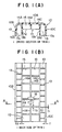
- the impact absorbing ribs 11 are formed on the back side of the trim 10 and, as shown in FIG. 1(A) and FIG. 1(B), include front ribs (front impact absorbing ribs) 12 formed on a back side of the central planar portion 10A of the trim 10 and also edge ribs (edge impact absorbing ribs) 13 formed on back sides of the curved side edge portions 10B,10C of the trim 10.
- front ribs front impact absorbing ribs
- edge ribs edge impact absorbing ribs
- the front ribs 12 have been constructed by connecting plural vertical ribs 14A,14B,14C, which are arranged at predetermined intervals to extend in a longitudinal direction of the pillar 1, with plural lateral ribs 15 which are arranged at predetermined intervals to extend in a lateral direction of the pillar 1.
- the front ribs are formed into a honeycomb structure with rectangular cells arranged therein.
- the centrally-located rib 14B, out of the vertical ribs 14A,14B,14C, and the plural lateral ribs 15 are set in length so that their free ends are brought into contact with or close to the inboard side 2A of the pillar inner 2 when the trim 10 is mounted on the pillar inner 2.
- the vertical ribs 14A,14C which are located on the sides of the curved side edge portions 10B,10C extend to the positions of the end edges 10b,10c of the curved side edge portions 10B,10C of the trim 10 so that the vertical ribs cover end faces of the flange portions 4,5 of the pillar 1, respectively.
- the left and right, vertical ribs 14A,14C are therefore formed to hold therebetween the flange portions 4,5 on which the flange trims 6,7 are mounted.
- the plural edge ribs 13 are arranged extending at predetermined intervals in the direction of the width of the pillar 1 so that the edge ribs 13 lie in parallel with the lateral ribs 15.
- Their side edges 13a are formed extending to the end edges 10b,10c of the curved side edge portions 10B,10C of the trim 10.
- their front end portions 13b are connected to the vertical ribs 14A,14C, whereby a sort of honeycomb structure is formed with substantially square cells arranged therein. Because relatively large rigidity is required for the curved side edge portions 10B,10C of the trim 10 in order to absorb impacts, the edge ribs 13 are arranged at a higher density than the lateral ribs 15 in this embodiment.
- Distances d1,d2 between the trim 10 and the pillar inner 2 are also set to conform with the rigidities of the individual ribs 13,14A-14C,15 so that, when an impact load of a predetermined magnitude is applied from the surface of the trim 10, its impact energy can be fully absorbed through buckling and subsequent destruction of the individual ribs 13,14A-14C,15 before the trim 10 comes to contact with the side of the pillar inner 2.
- the fixing of the trim 10 on the pillar inner 2 is effected by fittedly inserting mounting clips 16, which are attached to free end portions of the ribs 14A,15 on the back side of the trim 10, in fitted holes (not shown) formed on the side of the pillar inner 2 and then holding the flange portions 4,5 between the left and right, vertical ribs 14A and 14C.
- the impact energy absorbing structure according to the first embodiment of the present invention for the cabin is constructed as described above.
- the occupant is therefore protected by damping the resulting impact as will be described hereinafter.
- the vertical rib 14B and the numerous lateral ribs 15 primarily bear the impact and, while these ribs 14B,15 undergo buckling deformation and in some instances, destruction under the impact energy, the impact energy is absorbed before the central planar portion 10A of the trim 10 reaches the pillar inner 2.
- the impact can be damped to a certain level or less to protect the occupant.
- the edge ribs 13 and the vertical rib 14A or 14C primarily bear the impact and, while these ribs 13 and 14A or 14C undergo buckling deformation and in some instances, destruction under the impact energy, the impact energy is absorbed before the trim 10 reaches a corner portion of the pillar inner 2.
- the impact can be damped to a certain level or less to protect the occupant.
- the edge ribs 13 and the vertical rib 14A or 14C also primarily bear the impact in this case and, while these ribs 13 and 14A or 14C undergo buckling deformation and in some instances, destruction under the impact energy, the impact energy is absorbed before the trim 10 reaches the flange portion 4 or 5 of the pillar 1. Hence, even when the occupant hits the trim 10 in the direction b, the impact can be damped to a certain level or less to protect the occupant.
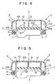
- the impact energy absorbing structure of this embodiment is also for the center pillar and in this embodiment, a gap of a predetermined width is formed between free edges of front ribs 12 and the inboard side 2A of the pillar inner 2.
- curved side edge portions 10B,10C of a trim 10 are closer to the flange portions 4,5 of the pillar 1 and their end edges 10b,10c are bent to embrace free ends of the flange portions 4,5 .
- end edge 10b of the curved front side edge portion 10B is somewhat separated from a free end of the flange portion 4 and the end edge 10c of the curved rear side edge portion 10C is closer to the free end of the flange portion.
- front-side edge ribs 17 are each provided with an indentation 17A along the flange trim 6 so that the flange portion 4 is embraced.
- Rear-side edge portion ribs 18 are formed only inside the flange trim 7.
- Free ends of the trim 10 are fixed by embracing the flange portions 4,5 by the curved side edge portions 10B,10C and the edge ribs 17,18 of the trim 10 as described above.
- front-side and rear-side edge ribs may be formed into the same shape by forming both of them into edge ribs 17 having indentations 17A or to form both of them into edge ribs 18 formed only inboard the flange trims 6,7.
- the impact energy absorbing structure according to the second embodiment of the present invention for the cabin is constructed as described above.
- a vertical rib 14B and numerous lateral ribs 15 therefore absorb the impact energy in substantially the same manner as in the first embodiment before a central planar portion 10A of the trim 10 reaches the pillar inner 2 while the vertical rib and lateral ribs undergo buckling deformation and in some instances, destruction under the impact energy.
- edge ribs 13 and the vertical rib 14A or 14C absorb the impact energy in substantially the same manner as in the first embodiment while the edge ribs and vertical rib undergo buckling deformation and in some instances, destruction under the impact energy.
- the front ribs 12, especially the lateral ribs 15 can absorb an impact applied in the direction b or b' or in the direction c or c' as described above while they themselves undergo deformation. Even in the case of large impact energy, the front ribs 12 also cooperate with the gap so that the impact energy can be absorbed before the trim 10 reaches a corner portion of the pillar inner 2.
- the impacts can also be damped to a certain level or less by the construction of the second embodiment as described above, thereby making it possible to protect the occupant.
- This embodiment also has the advantage that the flange portions 4,5 are completely covered by the trim 10 to improve the outward appearance, because the curved side edge portions 10B,10C, the edges of the trim 10, are formed to embrace the flange portions 4,5.
- the impact energy absorbing structure of this embodiment is also for a center pillar.
- the impact energy absorbing structure is intended to gradually absorb an impact in a direction a.
- a gap 8 of a predetermined width is formed between free edges of front ribs 12 and the inboard side 2A of the pillar inner 2, and a damping material (cushioning material) 19 such as a rubber pad is inserted in the gap 8.
- holes or indentations 20A,20B are formed in some or all of lateral ribs 15 and vertical ribs 14A-14C of the front ribs 12 and edge ribs 13 to adjust in a lowering direction the rigidity against a load in the direction a.
- curved side edge portions 10B,10C of the trim 10 are shaped so that they do not embrace the free ends of the flange portions 4,5 of the pillar 1 but cover the flange portions 4,5 from the inboard side only.
- the impact energy absorbing structure according to the third embodiment of the present invention for the cabin is constructed as described above.
- a vertical rib 14B and numerous lateral ribs 15 therefore absorb the impact energy in substantially the same manner as in the first and second embodiments before a central planar portion 10A of the trim 10 reaches the pillar inner 2 while the vertical rib and lateral ribs undergo buckling deformation and in some instances, destruction under the impact energy.
- the hole or indentations 20A,20B are formed in the individual ribs 12,13 and the damping material 19 such as a rubber pad is arranged between the free edges of the front ribs 12 and the pillar inner 2. Accordingly, an impact in the direction a can be damped into a small impact, a load in the direction a can be slowly damped, and the damping of an impact in the direction a can be surely performed, whereby the performance of occupant protection can be improved.
- edge ribs 13 and the vertical rib 14A or 14C can absorb an impact applied in the direction b or b' or in the direction c or c' in substantially the same manner as the first embodiment. Even in the case of large impact energy, the ribs 13,14A,14C and the front ribs 12 cooperate with each other so that the impact energy can be absorbed before the trim 10 reaches the corner portion of the pillar inner 2.
- the rigidity against a load in the direction b or b' or a load in the direction c or c' is adjusted so that the absorption of impact energy can be more gradually performed.
- certain desired ribs can be provided with thin-wall portions.
- the impact energy absorbing structure of this embodiment is also for a center pillar.
- elastic members (cushioning materials) 21 made of a hard or soft rubber material or the like are inserted within desired ones of cells formed between the individual ribs 12 and 13.
- a partial impact applied to the trim 10 is distributed to many ribs 12,13 through the elastic members 21, so that the impact energy can be absorbed through deformations of the ribs 12,13 and the elastic members 21.
- the structures of the ribs 12,13 themselves, the structures of the corresponding ribs in the structure of the third embodiment except for the omission of the holes or indentations 20A,20B and the formation of a gap 8 between the damping material 19 and the pillar inner 2 are used.
- the impact energy absorbing structure according to the fourth embodiment of the present invention for the cabin is constructed as described above, application of an impact to the trim 10 causes deformation of the ribs 12,13 and the elastic member 21 so that the impact energy can be absorbed. It is therefore possible to protect an occupant by preventing influence of these fragments against the occupant.
- the front rib 12 and edge ribs 13 are formed into the honeycomb structure composed of the arrays of rectangular cells.
- Honeycomb structures of various cell configurations are however conceivable, including one obtained by forming some or all of the front rib 12 and the edge ribs 13 into a general honeycomb structure constructed of arrays of hexagonal cells as shown, or example, in FIG. 6.
- the ribs 12,13 with rigidity-adjusting portions such as holes or indentations similar to those of the third embodiment or thin-walled portions at desired positions or to interpose the damping material 19 between the free edges of the front ribs 12 and the pillar inner 2.
- a gap can be arranged between the pillar inner 2 and the damping material 19.
- the trim 10 and the impact absorbing ribs 11 are both made of a resin.
- the impact absorbing ribs 11 are integrally molded with the trim 10. It is however contemplated to form the impact absorbing ribs 11 as discrete elements from the trim 10.
- the material is not limited to a resin material and use of another material such as rubber or paper is also contemplated.
- the absorption of impact energy must be completed before the trim 10 reaches the pillar inner 2. It is therefore necessary to leave a sufficient distance from the trim 10 to the pillar inner 2 (which also corresponds to the length of each rib), that is, to retain a sufficient energy absorbing stroke.
- the width of the pillar portion is increased by the jutting-out of the trim 10 as much as the thickness D2, it is desired to reduce the jutting-out.
- the impact energy absorbing structure according to this embodiment is also illustrated in a situation as applied to a center pillar as a structural member constituting a cabin of an automotive vehicle.
- FIG. 8 illustrates centering around a rear half portion of the center pillar.
- a front half portion is constructed in substantially the same design as the rear half portion.
- a trim (trim member) 10 is mounted to cover an inboard side 2A of a pillar inner (inner member) 2 of a pillar (center pillar) 1.
- a trim 10 is mounted inside the trim 10 to cover an inboard side 2A of a pillar inner (inner member) 2 of a pillar (center pillar) 1.
- impact absorbing ribs 11,12. are interposed between the inboard side 2A of the pillar inner 2 and the trim 20.
- designated at numeral 3 is a pillar outer (outer member).
- the trim 10 and the impact absorbing ribs 11,12 are all made of a resin and moreover, the impact absorbing ribs 11,12 and the trim 10 have been formed by monolithic molding.
- the trim 10 is provided with a front portion 10A facing a front wall (inboard front wall) of the inboard side 2A extending up and down centrally relative to the direction of the width of the pillar inner 2, and also with curved side edge portions (side edge portions) 10B,10C formed in configurations smoothly curved from opposite side edges of the front portion 10A so that the side edge portions cover, from the inboard side, flange portions 4,5 formed at edge portions of the pillar inner 2 (inboard edge portions of the pillar 1).
- end edges 10b,10c of the curved side edge portions 10B,10C are formed somewhat inboard the positions of the flange portions 4,5 and are arranged to cover the flange portions 4,5 from the inboard side.
- the curved side edge portions have therefore improved the inboard outward appearance around the pillar portion.
- the front portion 10A of the trim 10 is spaced by a predetermined distance D1 from the inboard side 2A of the pillar inner 2.
- the impact absorbing ribs 11,12 are formed on the back side of such a trim 10, and are arranged so that they are interposed between the front portion 10A and the inboard side 2A. Further, the impact absorbing rib 12 is arranged centrally relative to the direction of the width of the trim 10 and the impact absorbing ribs 11 are arranged on both sides of this impact absorbing rib 12.
- the impact absorbing ribs 11 are formed, on the back side of the front portion 10A of the trim 10, as flat walls perpendicular to the front portion 10A and also to the central portion of the inboard side 2A of the pillar inner 2.
- the impact absorbing rib 12 is formed of a pair of oblique flat wall 12A, which are arranged at a certain small angle with respect to the front portion 10A and also to the central portion of the inboard side 2A of the pillar inner 2, and a central planar wall 12B maintained in contact with the inboard side 2A of the pillar inner 2.
- screw holes 12C are formed so that the trim 10 is threadedly secured on the pillar inner 2 by way of screws 22.
- the impact absorbing rib 12 is constructed as an impact absorbing member and also as a mounting member.
- These impact absorbing ribs 11,12 primarily absorb an impact from a frontal direction of the pillar inner 2 (in the direction a) and also absorb portions of an impact from an oblique direction of the pillar inner 2 (in the direction a or b').
- the rigidities of the trim 10 itself and of the individual ribs 11,12 and the distances D1,D2 between the trim 10 and the pillar inner 2 are set so that in association with a below-described bracket 23 as an impact absorbing member made of a sheet metal, thee energy of an impact of a predetermined magnitude applied, for example, in the direction b, the direction b or b' or the direction c or c' can be absorbed before the trim 10 hits the surface of the pillar inner 2.
- the rigidities of the trim 10 and the individual ribs 11,12 can be set at desired values depending on the individual thicknesses T,T1,T2 and gaps D3,D4 although the rigidities vary depending of their materials.
- an angle ⁇ of the rib 12 can also contribute to the rigidity adjustment.
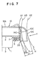
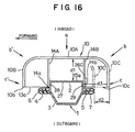
- the curved side edge portions 10B,10C are spaced only by a predetermined distance D2 from the flange portions 4,5 of the pillar inner 2, and between the curved side edge portions 10B,10C and the pillar inner 2, the trim-mounting bracket as a impact absorbing member made of a sheet metal (hereinafter called the "impact absorbing bracket") is interposed.
- This impact absorbing bracket 23 is made of the sheet metal, and is connected at opposite end portions thereof with the pillar inner 2 and the curved side edge portions 10B,10C by tapping screws or screws 24A,24B so that the trim 10 is fixed on the pillar inner 2. Tapping holes or screw holes 25 are therefore formed in the pillar inner 2 and the curved side edge portions 10B,10C.
- the impact absorbing bracket 23 made of the sheet metal has been bent beforehand at bent points P1,P2,P3.
- this impact absorbing bracket 23 absorbs impact energy while increasing the degrees of bending at the bent points P1,P2,P3.
- the deformation mode of the bracket at the time of bending is set in such a way that the end portions of the curved side edge portions 10B,10C are guided to a side inboard relative to the flange portions 4,5 as indicated by chain lines in FIG. 8.
- the bracket 23 primarily absorbs an impact applied in a direction of small obliqueness relative to the pillar inner 2 (in the direction c or c'), and in cooperation with the impact absorbing ribs 11,12, also absorbs a portion of an impact applied in a direction oblique to the pillar inner 2 (in the direction b or b').
- the rigidity of the bracket 23 is therefore set so that with respect to an impact of a predetermined magnitude applied in the direction c or c' or the direction b or b', for example, its energy can be absorbed before the trim 10 hits the surface of the pillar inner 2.
- the rigidity of the bracket 23 is set in relation to the rigidities and the like of the above-mentioned trim 10 and individual ribs 11,12.
- such deformation mode of the bracket 23 can be set by adjusting the fixed points of the bracket 23 (the points connected by the tapping screws or screws 24A,24B) and the distances between the bent points P,P2,P3.
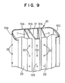
- the expression "points” like “bent points” and “fixed points” are used herein, they mean points as viewed in plan like FIG. 8, and that the bracket 23 actually has a length in a vertical direction as illustrated in FIG. 9 and the bent points and fixed points are in the forms of lines as a matter of fact.
- each impact absorbing rib 11 said end portion being on the side of the pillar inner 2 is maintained in contact with an end portion of the bracket 23, said end portion being on the side of the pillar inner 2.
- lip-shaped extensions 6A,7A jut out from outer end portions of flange trims fitted on the flange portions 4,5, respectively.
- These extensions 6A,7A are joined to outboard surfaces of the curved side edge portions 10B,10C of the trim 10.
- designated at signs 6B,7B are weather strips formed integrally with the flange portions 4,5, respectively.
- the impact energy absorbing structure according to the fifth embodiment of the present invention for the cabin is constructed as described above.
- the occupant is therefore protected by damping the resulting impact as will be described hereinafter.
- the impact absorbing ribs 11,12 primarily bear this impact and, while these ribs 11,12 undergo buckling deformation and in some instances, destruction under the impact energy, the impact energy is absorbed before the front portion 10A of the trim 10 reaches the pillar inner 2.
- the impact can be damped to a certain level or less to protect the occupant.
- the ribs 11,12 bear this impact in cooperation with the impact absorbing bracket 23 and, while under the impact energy these ribs 11,12 undergo buckling deformation and in some instances, destruction and the bracket 23 undergoes bending deformation, the impact energy is absorbed before the trim 10 reaches a corner portion of the pillar inner 2.
- the impact can be damped to a certain level or less to protect the occupant.
- the bracket 23 When an impact is applied to the curved side edge portion 10B or 10C in the direction c' or c as shown, for example, in FIG. 8, the bracket 23 primarily bears the impact in this case and, while the bracket 23 undergoes bending deformation (through elastic deformation or plastic deformation), the impact energy is absorbed before the trim 10 reaches the position of the flange portion 4 or 5 of the pillar 1. Hence, even when the occupant hits the trim 10 in the direction c or c', the impact can be damped to a certain level or less to protect the occupant.
- the end portion of the curved side edge portion 10B or 10C advances inboard the flange portion 4 or 5 under the guidance of bending of the bracket 23 as indicated by chain lines in FIG. 8. It is therefore possible to continue the absorption of the impact energy until the surface of the curved side edge portion 10B or 10C reaches the free end or so of the flange portion 4 or 5.
- trim-mounting bracket 23 contributes to a reduction in the number of parts and/or brackets because it also serves as an impact absorbing member.
- the curved side edge portion 10B, 10C of the trim 10 are arranged to cover the flange portions 4,5 from the inboard side so that the external appearance of the cabin is improved around the pillar portion.
- the lip-shaped extensions 6A,7A of the flange trims 6,7 are joined to the outboard surfaces of the curved side edge portions 10B,10C of the trim 10 so that the interior of the trim 10 is shielded. Therefore the construction is also effective in improving the external appearance (outward appearance) of the vehicle.
- the end portions of the impact absorbing ribs 11, said end portions being on the side of the pillar inner, are kept in contact with end portions of the brackets 23, said end portions being on the side of the pillar inner 2, in this embodiment.
- deformation of the bracket 23 can also be used. This is effective in improving the impact absorbing performance and in increasing the stroke S for absorbing impact energy from the frontal direction (in the direction a) or from an oblique direction (the direction b or b').
- the bracket 23 is formed in the shape of a plate continuously extending in the direction of the length of the pillar 1 in this embodiment.
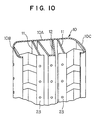
- the bent portions (i.e., the portions where impact energy is absorbed) of the bracket 23 can be arranged in a discontinuous form as shown, for example, in FIG. 10. In this modification illustrated in FIG. 10, only the bent portions are cut off. It is however possible to divide the bracket 23 itself into plural pieces and to arrange it as discontinuous members.
- the ribs 11,12 are integrally formed with the trim 10. They can however be discrete members. Further, like the ribs 11,12, members for absorbing impact energy from a frontal direction (in the direction a) or from an oblique direction (in the direction b or b') can be made of a metal or the like other than a resin to make use of its elastic deformation or plastic deformation. A cushioning material such as rubber or urethane can also be used in combination with these members.
- FIG. 12 to FIG. 15 the sixth embodiment of the present invention will be described. This embodiment will be described taking, as an example, the impact energy absorbing structure applied to a center pillar.
- a trim (trim member) 10 is arranged so that an inboard side 2A of a pillar inner (inner member) 2 of a pillar (center pillar) 1 is covered. Inside the trim 10, impact absorbing ribs 11 and a pillar-contacting portion 26 are arranged. By mounting the trim 10 on the pillar inner 2 so that the pillar-contacting portion 26 is kept in contact with the pillar inner 2, the impact absorbing ribs 11 are interposed between the inboard side 2A of the pillar inner 2 and the trim 10.
- the trim 10 and the impact absorbing ribs 11 are both made of a resin.
- the impact absorbing ribs 11 have been formed with the trim 10 by monolithic molding.
- numeral 3 indicates a pillar outer (outer member).
- the pillar inner 3 and the pillar outer 3 are provided at opposite edge portions thereof with flange portions and are joined together at the corresponding flange portions by welding or the like, whereby joined flange portions (hereinafter called the "flange portions") are formed.
- the pillar inner 2 is provided with a front wall 27 directed straight inboard (in the direction of the width of the vehicle) and also with side edge wall portions 28,29 directed inward and frontward (in the direction of the length of the vehicle) and inward and rearward (in the direction of the length of the vehicle), respectively.
- the front wall portion 27 extends in the pillar inner 2 up and down centrally relative to the direction of the width of the vehicle, while the side edge wall portions 28,29 extend in the pillar inner 2 up and down on opposite sides of the front wall portion 27.
- the flange portions 4,5 are formed outside the side edge wall portions 28,29.
- the side edge wall portions 28,29 are directed in a direction substantially perpendicular to the front wall portion 27.
- the trim 10 is provided with a front portion 10A facing the front wall portion 27, which extends up and down centrally relative to the direction of the width of the pillar inner 2, and also with curved side edge portions 10B,10C formed in configurations smoothly curved from opposite side edges of the front portion 10A.
- the curved side edge portions 10B,10C cover the side edge wall portions 28,29, which are formed on the edge portions of the pillar inner 2, and also the flange portions 4,5 from the inboard side.
- end edges 10b,10c of the curved side edge portions 10B,10C are located at positions somewhat inboard the positions of the flange portions 4,5.
- the pillar-contacting portion 26 of the trim 10 is provided with a front portion 26A kept in contact with the front wall portion 27 of the pillar inner 2 and also with side edge portions 26B,26C maintained in contact with the side edge wall portions 28,29.
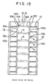
- the impact absorbing ribs 11 are formed on the back side of the trim 10 and, as is illustrated in FIG. 12 and FIG. 13, are provided with front impact absorbing ribs (hereinafter called the “front ribs”) 12 formed on the back side of the front portion 10A of the trim 10 and also with edge impact absorbing ribs (hereinafter called the “edge ribs”) 13 formed on back sides of the curved side edge portions 10B,10C of the trim 10.
- front ribs front impact absorbing ribs
- edge ribs edge impact absorbing ribs
- the front ribs 12 are constructed by connecting plural vertical ribs 14A,14B, which are arranged at predetermined intervals so that they extend in the direction of the length of the pillar 1, with plural lateral ribs 15 which are arranged at predetermined intervals so that they extend in the direction of the width of the pillar 1.
- the front ribs 12 are formed into a honeycomb structure in which rectangular cells are arrayed.
- free ends 14a,14b of the vertical ribs 14A,14B and free ends of the lateral ribs 15 are all joined to the front portion 26A of the pillar-contacting portion 26 so that with respect to an impact from a front direction (in the direction a), impact energy can be absorbed while exhibiting adequate rigidity in association with the front wall portion 27 of the pillar inner 2 via the front portion 26A.
- the plural edge ribs 13 are arranged at predetermined intervals so that they extend in the direction of the width of the pillar 1 in parallel with the lateral ribs 15. Their side edges 13a are formed up to the end edges of the curved side edge portions 10B,10C of the trim 10. In addition, the free ends 13b are joined to outer surfaces of the vertical ribs 14A,14B and side edge portions 26B,26C of the pillar-contacting portion 26, whereby a sort of honeycomb structure with substantially square cells arrayed therein is formed.
- relatively large rigidity is required for the curved side edge portions 10B,10C of the trim 10 to absorb impacts so that the edge ribs 13 are arranged at a higher density than the lateral ribs 15.
- the side edge portions 26B,26C of the pillar-contacting portion 26 and the side edges 13a of the edge ribs 13 are located inboard the flange trims 6,7 of the flange portions 4,5 similarly to the end edges 10b,10c of the curved side edge portions 10B,10C of the trim 10.
- the curved side edge portion 10B or 10C of the trim 10 can undergo displacement without interference with the corresponding flange portion 4 or 5.
- Distances d1,d2,d3 between the trim 10 and the pillar inner 2 are also set to conform with the rigidities of the individual ribs 13,14A,14B,15 so that, when an impact load of a predetermined magnitude is applied from the surface of the trim 10, its impact energy can be fully absorbed through buckling and subsequent destruction of the individual ribs 13,14A,14B,15 before the trim 10 comes to contact with the side of the pillar inner 2.
- FIG. 14 illustrates produced loads versus amounts of deformation. It is desired to set in such a way that the produced load as a function of the amount of deformation falls, for example, within such a range as indicated by hatching in the diagram. It is particularly desired to limit the produced load within a range of from L1 to L2. In this case, it is desired to make the amount of the deformation as small as possible.
- the number of effective lattice points means the number of lattice points acted on by an object out of points (lattice points) where vertical ribs and lateral ribs intersect with each other as indicated by letter K in FIG. 13.
- the impact energy absorbing structure according to the sixth embodiment of the present invention for the cabin is constructed as described above.
- the occupant is therefore protected by damping the resulting impact as will be described hereinafter.
- the lateral ribs 15 and the vertical ribs 14A,14B primarily bear the impact and, while these ribs 14A,14B,15 undergo buckling deformation and in some instances, destruction under the impact energy, the impact energy is absorbed before the front portion 10A of the trim 10 reaches the pillar inner 2.
- the impact can be damped to a certain level or less to protect the occupant.
- the edge ribs 13 and the rib 14A or 14C primarily bear the impact and, while these ribs 13 and rib 14A or 14C undergo buckling deformation and in some instances, destruction under the impact energy, the impact energy is absorbed before the trim 10 reaches a corner portion of the pillar inner 2.
- the impact can be damped to a certain level or less to protect the occupant.
- the edge ribs 13 When an impact is applied to the curved side edge portion 10B or 10C in the direction c' or c as shown, for example, in FIG. 12, the edge ribs 13 also primarily bear the impact in this case and, while the ribs 13 undergo buckling deformation and in some instances, destruction under the impact energy, the impact energy is absorbed before the trim 10 reaches the position where the flange portion 4 or 5 of the pillar 1 is exposed. Hence, even when the occupant hits the trim 10 in the direction b, the impact can be damped to a certain level or less to protect the occupant.
- the curved side edge portion 10B or 10C of the trim 10 undergoes displacement in addition to deformation and destruction of the ribs 13.
- the curved side edge portion 10B or 10C can undergo displacement without interference with the corresponding flange portion 4 or 5.
- the distance (jutting-out width) D1 between the surface of the trim 10 and the end edge of the flange portion 5 can be used in its entirety as an effective energy absorbing stroke S.
- the curved side edge portion 10B,10C of the trim 10 are arranged to cover the flange portions 4,5 from the inboard side so that the external appearance of the cabin is improved around the pillar portion.
- the structure by omitting the pillar-contacting portion 26 of the trim 10, joining inner sides of free end portions of the ribs 14A,14B to the side edge wall portions 28,29 of the pillar inner 2 and keeping the free ends 15a of the ribs 15 in contact with the front wall portion 27 of the pillar inner 2.
- the free ends 14a,14b of the ribs 14A,14B are both extended to the side edges 13a of the edge ribs 13 and also to the end edges 10b,10c of the curved side edge portions 10B,10C of the trim 10.
- the impact energy absorbing structure of this embodiment is also intended for a center pillar but in this embodiment, is intended for a center pillar equipped at an intended position of impacts with a height adjuster rail for a seat belt anchor (a member of a seat belt system).
- the adjuster rail as illustrated in FIG. 19, is adapted to adjust the height of a seat belt anchor 31 and is generally arranged at a position which an occupant in a vehicle may hit.
- the adjuster rail 30 is provided at opposite side portions thereof with walls (side edge wall portions) 32A,32B facing the front and rear of the vehicle, respectively.
- a slot 33 is formed through the trim 10 at a position facing the adjuster rail 30.
- the trim 10 is provided with a front portion 10A and curved side edge portions 10B,10C substantially like the sixth embodiment. Inside the trim 10, impact absorbing ribs 11 are arranged. Further, the trim 10 and the impact absorbing ribs 11 are both made of a resin, and have been formed by monolithic molding.
- the impact absorbing ribs 11 are provided with front ribs 12, which are formed on the back side of the front portion 10A of the trim 10, and also with edge ribs 13 formed on the back sides of the curved side edge portions 10B,10C of the trim 10.
- the front ribs 12 have been constructed by joining plural vertical ribs 14A,14B, 14C,14D, which are arranged at predetermined intervals so that they extend in the direction of the length of the pillar 1, with plural lateral ribs 15A,15B arranged at predetermined intervals so that they extend in the direction of the width of the pillar 1.
- the front rib is formed into a honeycomb structure with rectangular cells arrayed therein.
- the plural edge ribs 13 are arranged at predetermined intervals so that they extend in the direction of the width of the pillar 1 in parallel with the lateral ribs 15A,15B.
- Their side edges 13a are formed up to the end edges 10b,10c of the curved side edge portions 10B,10C of the trim 10.
- the free ends 13b are joined to outer surfaces of the vertical ribs 14A,14B, whereby a sort of honeycomb structure with substantially square cells arrayed therein is formed.
- relatively large rigidity is required for the curved side edge portions 10B,10C of the trim 10 to absorb impacts so that the edge ribs 13 are arranged at a higher density than the lateral ribs 15.
- the vertical ribs 14A,14B are arranged close to the walls 32A,32B so that the vertical ribs can come to contact with the walls when impacts are applied at small angles (for example, in the direction c and the direction c').
- a recess 10D is formed around the slot 33 in the front portion 10A of the trim 10.
- the impact energy absorbing structure according to the seventh embodiment of the present invention for the cabin is constructed as described above.
- the lateral ribs 15A,15B and the vertical ribs 14A,14B,14C,14D primarily absorb the impact energy before the front portion 10A of the trim 10 reaches the pillar inner 2 while these ribs undergo buckling deformation and in some instances, destruction under the impact energy.
- the impact can be damped to a certain level or less to protect the occupant.
- the impact energy is absorbed before the trim 10 reaches the position where the flange portion 4 or 5 of the pillar 1 is exposed, while primarily the edge ribs 13 undergo buckling deformation and in some instances, destruction under the impact energy.
- the impact can be damped to a certain level or less to protect the occupant.
- the curved side edge portion 10B or 10C of the trim 10 undergoes displacement in addition to deformation and destruction of the ribs 13.
- the curved side edge portion 10B or 10C can undergo displacement without interference with the corresponding flange portion 4 or 5.
- the distance (jutting-out width) D1 between the surface of the trim 10 and the end edge of the flange portion 5 can be used in its entirety as an effective energy absorbing stroke S.
- this embodiment can obtain similar advantageous effects as the sixth embodiment.
- the ribs 11 are integrally formed with the trim 10. They can however be discrete members.
- a metal or the like other than a resin can be used to make use of its elastic deformation or plastic deformation.
- a cushioning material such as rubber or urethane can also be used.
- Each of the above-mentioned embodiments is intended for a center pillar.
- the present structure can be applied for the absorption of impact energy for a cabin wall other than a center pillar and can be applied, for example, to other pillars such as front pillars and rear pillars.
- the impact energy absorbing structure according to the present invention for the vehicle cabin makes it possible to absorb impact energy, which is directed toward a structural member, by an impact absorbing member.
- the impact can be damped to protect the occupant.
- application of the impact energy absorbing structure of the present invention for the cabin to a pillar which is one of structural elements of a vehicle and is required to have high rigidity and strength upon constructing a cabin to protect an occupant, can further enhance the occupant protecting effects.
- resin-made impact absorbing ribs can be used as the impact absorbing member so that the structure can be formed easily at low cost.
Landscapes
- Engineering & Computer Science (AREA)
- Mechanical Engineering (AREA)
- Vehicle Interior And Exterior Ornaments, Soundproofing, And Insulation (AREA)
- Body Structure For Vehicles (AREA)
Claims (23)
- Structure d'absorption d'énergie d'impact pour l'habitacle d'un véhicule automobile, comprenant:caractérisé en ce que ledit élément de garniture (10) comprend au moins une partie de bord latérale recourbée (10B, 10C) couvrant une partie de bride (4, 5) correspondante formée à une partie de bord dudit montant (1), la partie de bord latérale recourbée (10B, 10C) étant ménagée à l'intérieur relativement à ladite partie de bride (4, 5), et en ce que ladite partie de bord latérale (10B, 10C) est également ménagée à une partie de celle-ci faisant face à ladite partie de bride correspondante (4, 5) avec lesdites membrures d'absorption d'impact (11).un élément de garniture (10) couvrant une face intérieure d'un montant (1) constituant ledit habitacle, etdes membrures d'absorption d'impact (11) disposées entre une face intérieure (2A) dudit montant (1) et dudit élément de garniture (10) de sorte à pouvoir absorber l'énergie d'impact dirigée d'une surface dudit élément de garniture (10) vers ledit montant (1), lesdites membrures d'absorption d'impact (11) étant intégralement formées avec ledit élément de garniture (10) en un matériau résineux,
- Structure selon la revendication 1, dans laquelle lesdites membrures d'absorption d'impact (11) sont formées dans une structure alvéolaire s'étendant dans une direction sensiblement perpendiculaire audit élément de garniture (10).
- Structure selon la revendication 1 ou 2, dans laquelle un matériau amortisseur (19) est intercalé entre ledit élément de garniture (10) et ledit montant (1).
- Structure selon la revendication 2 ou 3, dans laquelle ladite structure alvéolaire a été formée par connexion d'une pluralité de membrures verticales (14A, 14B, 14C, 14D), qui s'étendent dans une direction longitudinale dudit montant (1), avec une pluralité de membrures latérales (15, 15A, 15B) qui s'étendent dans une direction latérale dudit montant (1).
- Structure selon la revendication 4, dans laquelle ledit élément de garniture (10) est ménagé à l'intérieur de ladite partie de bord latérale (10B, 10C), avec une pluralité de membrures de bord (13) qui sont parallèles auxdites membrures latérales (15A, 15B), et lesdites membrures de bord (13) sont connectées à une membrure verticale la plus proche (14A, 14C) parmi ladite pluralité de membrures verticales (14A, 14B, 14C, 14D).
- Structure selon la revendication 5, dans laquelle lesdites membrures latérales (15, 15A, 15B) et ledit montant (1) sont espacés les unes des autres par un vide (8).
- Structure d'absorption d'énergie d'impact pour l'habitacle d'un véhicule automobile, comprenant :caractérisée en ce que ladite partie de bord latérale (10B) couvre une partie du bord latérale correspondante dudit montant (1) et ledit élément d'absorption d'impact (11) est disposé à l'intérieur de ladite partie de bord latéral (10B) dudit élément de garniture (10) de sorte que ledit élément d'absorption d'impact peut absorber l'énergie d'impact appliquée dans une direction extérieure et en sens oblique latéral relativement audit montant (1) et en ce que lors de l'absorption de ladite énergie d'impact, ledit élément d'absorption d'impact guide ladite partie de bord latéral (10B) dudit élément de garniture (10) vers une position où ladite partie de bord latéral est maintenue hors de contact avec un bord latéral dudit montant (1).un élément de garniture (10) couvrant une face intérieure d'un montant (1) constituant ledit habitacle;un élément d'absorption d'impact (11) disposé entre ladite face intérieure (2A) dudit montant (1) et dudit élément de garniture (10) de sorte à pouvoir absorber l'énergie d'impact dirigée d'une surface dudit élément de garniture (10) vers ledit montant (1), et un élément de garniture (10) pourvu d'une partie avant (10A) couvrant une partie avant intérieure dudit montant (1) etune partie de bord latérale (10B) de sorte que ledit élément de garniture couvre la face intérieure dudit montant (1),
- Structure selon la revendication 7, dans laquelle en tant qu'élément d'absorption d'impact (11), des membrures d'absorption d'impact sont disposées à l'intérieur de ladite partie avant (10A) de sorte que lesdites membrures d'absorption d'impact peuvent absorber l'énergie d'impact appliquée dans une direction extérieure et latérale relativement audit montant (1).
- Structure selon la revendication 8, dans laquelle lesdites membrures d'absorption d'impact (11) et ledit élément de garniture (10) sont formés intégralement en un matériau résineux.
- Structure selon la revendication 7 ou 9, dans laquelle ledit élément d'absorption d'impact est pourvu d'un élément flexible (23) qui peut subir une déformation selon un mode de déformation prédéterminé à la suite de l'absorption de l'énergie d'impact.
- Structure selon la revendication 10, dans laquelle ledit élément d'absorption d'impact est pourvu d'un élément en tôle métallique (23) comportant au moins un point pliable formé par avance de sorte que ledit élément en tôle métallique peut subir une déformation selon ledit mode de déformation prédéterminé.
- Structure selon la revendication 10 ou 11, dans laquelle ledit élément d'absorption d'impact est pourvu d'un support de fixation de l'élément de garniture (23) connecté à une extrémité de celui-ci audit montant (1) et à une extrémité opposée de celui-ci à ladite partie de bord latéral (10B) dudit élément de garniture (10).
- Structure selon la revendication 7 ou 12, dans laquelle
ledit montant (1) est pourvu audit bord latéral de celui-ci d'une partie de bride (4, 5) et
ladite partie de bord latérale (10B) dudit élément de garniture (10) est disposé de sorte que ladite partie de bord latérale couvre ladite partie de bride sur une face intérieure relativement à ladite partie de bride à une distance équivalente à une course d'absorption d'énergie d'impact. - Structure selon la revendication 13, dans laquelle ladite partie de bride (4, 5) est pourvue d'une garniture de bride (6, 7) et ladite garniture de bride (6, 7) . est pourvue d'une rallonge (6A, 7A) formée sur celle-ci de sorte que ladite rallonge est maintenue en contact avec un bord de ladite partie de bord latéral (10B) dudit élément de garniture (10).
- Structure d'absorption d'énergie d'impact pour l'habitacle d'un véhicule automobile, comprenant:caractérisé en ce queun élément structurel (1) constituant ledit habitacle;un élément de garniture (10) pourvu d'une partie avant (10A) faisant face à une partie avant intérieure dudit élément structurel (1) ainsi que d'une partie de bord latérale (10B) faisant face à une partie de bord latérale intérieure correspondante dudit élément structurel (1) de sorte que ledit élément de garniture couvre ladite face intérieure dudit élément structurel (1) ;
l'élément structurel (1) est formé d'un élément intérieur (2) et d'un élément extérieur (3) solidarisés sur des parties de bride (4, 5) ménagées sur les bords latéraux desdits éléments intérieurs et extérieurs (2, 3),
une partie de cloison de bord latéral (28, 29) est formée sur ladite partie de bord intérieur à une position adjacente à une partie de base de ladite bride (4, 5) sur une face dudit élément intérieur (2) de sorte que ladite partie de cloison de bord latéral s'étend vers ladite partie de bord latéral (10B) dudit élément de garniture (10), et
en ce que des membrures d'absorption d'impact de bord (13) sont disposées entre ladite partie de cloison de bord latéral (28, 29) et ladite partie de bord latéral (10B) dudit élément de garniture (10) de sorte que l'énergie d'impact appliquée à un petit angle dans une direction partant d'une surface de ladite partie de bord latéral (10B) dudit élément de garniture (10) vers la proximité de ladite partie de bride (4, 5) peut être absorbée. - Structure selon la revendication 15, dans laquelle ledit élément structurel (1) est constitué d'un montant disposé dans ledit véhicule automobile et formé d'un élément intérieur (2) et d'un élément extérieur (3) solidarisés sur des . parties de bride (4, 5) ménagées sur des bords latéraux desdits éléments intérieurs et extérieurs, et
ledit élément de garniture (10) est pourvu d'une partie avant (10A) faisant face à une partie avant intérieure dudit montant (1) ainsi que d'une partie de bord latéral (10B) faisant face à une partie de bord latéral intérieure correspondante dudit montant (1) de sorte que l'élément de garniture couvre une face intérieure dudit montant (1). - Structure selon la revendication 16, dans laquelle ladite partie de cloison de bord latéral (28, 29) est formée sur ledit élément intérieur (2).
- Structure selon la revendication 16, dans laquelle ladite partie de cloison de bord latéral est formée sur un élément de ceinture de sécurité (30) monté sur ledit élément intérieur (2).
- Structure selon la revendication 16 ou 17, dans laquelle lesdites membrures d'absorption d'impact de bord (13) et ledit élément de garniture (10) sont formés intégralement en un matériau résineux.
- Structure selon la revendication 16 ou 19, dans laquelle les membrures d'absorption d'impact avant (12) sont disposées entre la partie avant intérieure dudit montant (1) et ladite partie avant (10) dudit élément de garniture (10) de sorte que l'énergie d'impact appliquée dans une direction latérale extérieure audit élément de garniture (10) peut être absorbée.
- Structure selon la revendication 16 ou 20, dans laquelle lesdites membrures d'absorption d'impact de bord (13) et lesdites membrures d'absorption d'impact avant (12) sont formées dans une structure alvéolaire s'étendant dans une direction sensiblement perpendiculaire audit élément de garniture (10).
- Structure selon la revendication 21, dans laquelle lesdites membrures d'absorption d'impact avant (12) ont été formées en connectant une pluralité de membrures verticales (14A, 14B), qui s'étendent dans une direction longitudinale dudit montant (1), à une pluralité de membrures latérales (15) qui s'étendent dans une direction latérale dudit montant (1), et lesdites membrures d'absorption d'impact avant (12) proprement dites sont formées dans ladite structure alvéolaire.
- Structure selon la revendication 16 ou 22, dans laquelle ledit élément de garniture (10) est conçu de sorte qu'une extrémité libre d'un bord latéral dudit élément de garniture est situé à l'intérieur de ladite portion de bride (4, 5) formée sur une partie de bord dudit montant (1).
Applications Claiming Priority (10)
| Application Number | Priority Date | Filing Date | Title |
|---|---|---|---|
| JP20081794 | 1994-08-25 | ||
| JP200817/94 | 1994-08-25 | ||
| JP20081794A JP3320213B2 (ja) | 1994-08-25 | 1994-08-25 | 車室内の衝撃エネルギ吸収構造 |
| JP179215/95 | 1995-07-14 | ||
| JP7179213A JPH0924785A (ja) | 1995-07-14 | 1995-07-14 | 車室内の衝撃エネルギ吸収構造 |
| JP17921595 | 1995-07-14 | ||
| JP7179215A JPH0924786A (ja) | 1995-07-14 | 1995-07-14 | 車室内の衝撃エネルギ吸収構造 |
| JP179213/95 | 1995-07-14 | ||
| JP17921395 | 1995-07-14 | ||
| PCT/JP1995/001678 WO1996005984A1 (fr) | 1994-08-25 | 1995-08-24 | Structure d'absorption d'energie d'impact pour l'interieur d'un vehicule |
Publications (3)
| Publication Number | Publication Date |
|---|---|
| EP0776792A1 EP0776792A1 (fr) | 1997-06-04 |
| EP0776792A4 EP0776792A4 (fr) | 1997-12-10 |
| EP0776792B1 true EP0776792B1 (fr) | 2002-05-15 |
Family
ID=27324698
Family Applications (1)
| Application Number | Title | Priority Date | Filing Date |
|---|---|---|---|
| EP95929218A Expired - Lifetime EP0776792B1 (fr) | 1994-08-25 | 1995-08-24 | Structure d'absorption d'energie d'impact pour l'interieur d'un vehicule |
Country Status (5)
| Country | Link |
|---|---|
| US (2) | US6050631A (fr) |
| EP (1) | EP0776792B1 (fr) |
| KR (1) | KR100237663B1 (fr) |
| DE (1) | DE69526736T2 (fr) |
| WO (1) | WO1996005984A1 (fr) |
Families Citing this family (54)
| Publication number | Priority date | Publication date | Assignee | Title |
|---|---|---|---|---|
| JP3000898B2 (ja) * | 1995-07-12 | 2000-01-17 | トヨタ自動車株式会社 | 自動車の衝撃エネルギ吸収構造 |
| GB2318551B (en) * | 1996-10-25 | 2001-04-18 | Nissan Motor | Interior material for automotive vehicle |
| DE29802474U1 (de) * | 1998-02-13 | 1998-04-23 | TRW Automotive Safety Systems GmbH, 63743 Aschaffenburg | Lenkrad für Kraftfahrzeuge |
| JP3542288B2 (ja) * | 1998-10-07 | 2004-07-14 | 森六株式会社 | 自動車におけるインストルメントパネル支持構造 |
| US6199907B1 (en) * | 1998-11-17 | 2001-03-13 | Chrysler Corporation | Method and apparatus for absorbing impact energy |
| JP3223896B2 (ja) * | 1998-12-17 | 2001-10-29 | トヨタ自動車株式会社 | 自動車の車体上部の衝撃エネルギ吸収構造 |
| JP3097684B2 (ja) * | 1999-01-14 | 2000-10-10 | トヨタ自動車株式会社 | 自動車の車体上部の衝撃エネルギ吸収構造 |
| JP2001047954A (ja) | 1999-08-09 | 2001-02-20 | Kanegafuchi Chem Ind Co Ltd | 車両用内装材 |
| US6273469B1 (en) * | 1999-09-01 | 2001-08-14 | Trw Vehicle Safety Systems Inc. | Insert for protecting a vehicle occupant's head from an impact |
| US6264238B1 (en) * | 1999-09-28 | 2001-07-24 | Daimlerchrysler Corporation | Reactive surface rib cartridge countermeasure for vehicle interior hard trim applications |
| US6390538B1 (en) * | 1999-11-12 | 2002-05-21 | Kaneka Corporation | Impact absorbing member for vehicle interior |
| US6391232B1 (en) | 1999-12-06 | 2002-05-21 | Magna Interior Systems, Inc. | Integrated soft pads for one step molded parts |
| FR2804920B1 (fr) * | 2000-02-11 | 2002-04-26 | Renault | Agencement interieur pour un habitacle d'un vehicule automobile |
| DE10011908C1 (de) * | 2000-03-11 | 2001-03-15 | Porsche Ag | Vorrichtung für einen Gurthöhenversteller eines Sicherheitsgurtsystems |
| DE10011906C1 (de) * | 2000-03-11 | 2001-08-09 | Porsche Ag | Vorrichtung für einen Gurthöhenversteller eines Sicherheitsgurtsystems |
| JP2002166804A (ja) * | 2000-12-01 | 2002-06-11 | Kojima Press Co Ltd | 車両用衝撃吸収構造体及びそれを用いた車両用内装部品の衝撃吸収構造 |
| DE10063339C1 (de) * | 2000-12-19 | 2001-12-06 | Porsche Ag | Energieabsorbierendes Deformationselement |
| US6454305B1 (en) * | 2000-12-22 | 2002-09-24 | Daimlerchrysler Corporation | Trim panel assembly for a motor vehicle |
| US6758507B2 (en) | 2001-03-01 | 2004-07-06 | Venture Industries | Energy absorbing external component for vehicle |
| JP3610927B2 (ja) * | 2001-06-19 | 2005-01-19 | 日産自動車株式会社 | 自動車の車体上部構造 |
| USD476097S1 (en) | 2002-01-02 | 2003-06-17 | Honda Giken Kogyo Kabushiki Kaisha | Integrated grab rail and map light |
| US6523888B1 (en) | 2002-01-04 | 2003-02-25 | Honda Giken Kogyo Kabushiki Kaisha | Integrated light and grab rail assembly |
| KR100506720B1 (ko) * | 2003-02-17 | 2005-08-05 | 현대자동차주식회사 | 커튼 에어백 장착 차량의 필러트림 설치 구조 |
| DE102004010273A1 (de) * | 2004-03-03 | 2005-09-29 | Benteler Automobiltechnik Gmbh | Cabriolet |
| DE102004039690B4 (de) * | 2004-08-16 | 2008-11-27 | Webasto Ag | Scheibenanordnung für ein Fahrzeug |
| CN101312858B (zh) * | 2005-11-23 | 2011-06-08 | 奈特夏普能源管理有限公司 | 用于行人、乘员、车辆的可变能量管理系统 |
| JP4260159B2 (ja) * | 2005-11-28 | 2009-04-30 | トヨタ車体株式会社 | 車両のピラーガーニッシュの取付構造 |
| US7344185B2 (en) * | 2006-02-07 | 2008-03-18 | Toyota Motor Engineering & Manufacturing North America, Inc. | Applied load displacement structure for pillar garnish |
| US7513528B2 (en) * | 2006-02-07 | 2009-04-07 | Toyota Motor Engineering & Manufacturing North America, Inc. | Vehicle glove box door incorporating variations in rib structure for adjusting impact deformation proximate to respective knee and hand hit areas |
| DE102007017090B4 (de) * | 2006-11-16 | 2015-04-30 | Johnson Controls Gmbh | Ausstattungsteil, insbesondere für ein Kraftfahrzeug, mit einem ersten Teilbereich und einem einstückig mittels eines Verbindungsbereichs angebundenen zweiten Teilbereich |
| JP4341039B2 (ja) * | 2007-05-31 | 2009-10-07 | 株式会社イノアックコーポレーション | 車両用内装部材 |
| DE102007034313A1 (de) * | 2007-07-24 | 2009-01-29 | Lisa Dräxlmaier GmbH | Energieabsorber zur Verwendung als Aufprallschutz in einem Kraftfahrzeug |
| JP5035218B2 (ja) * | 2007-12-27 | 2012-09-26 | 豊田合成株式会社 | 自動車用ドア |
| US7810869B2 (en) * | 2008-10-07 | 2010-10-12 | Honda Motor Co., Ltd. | Glove box knee bolster assembly for vehicle and method of manufacturing |
| FR2942438B1 (fr) * | 2009-02-26 | 2013-03-01 | Peugeot Citroen Automobiles Sa | Dispositif d'habillage interieur de vehicule |
| CN102933431B (zh) * | 2010-05-28 | 2016-03-16 | 京洛株式会社 | 冲击吸收体 |
| FR2975354B1 (fr) * | 2011-05-17 | 2014-01-03 | Faurecia Interieur Ind | Ensemble de panneau de garnissage de vehicule automobile |
| US9457736B2 (en) * | 2011-09-23 | 2016-10-04 | Saint-Gobain Glass France | Pillar covering for motor vehicles |
| EP2758277B3 (fr) * | 2011-09-23 | 2022-07-20 | Saint-Gobain Glass France | Habillage de montant d'un véhicule automobile |
| CN106458131A (zh) | 2014-06-16 | 2017-02-22 | 沙特基础工业全球技术有限公司 | 制备层压板的方法、吸能装置、吸能装置组合物及成形工具 |
| CN107074193B (zh) * | 2014-08-28 | 2019-03-15 | 河西工业株式会社 | 座椅安全带锚固螺栓附近的冲击吸收构造 |
| US10053046B2 (en) * | 2015-09-04 | 2018-08-21 | Ford Global Technologies, Llc | Side pillar air curtain guide |
| US11332061B2 (en) | 2015-10-26 | 2022-05-17 | Atnomity Ltd. | Unmanned carrier for carrying urban manned vehicles |
| US10717406B2 (en) | 2015-10-26 | 2020-07-21 | Active Knowledge Ltd. | Autonomous vehicle having an external shock-absorbing energy dissipation padding |
| US10059347B2 (en) | 2015-10-26 | 2018-08-28 | Active Knowledge Ltd. | Warning a vehicle occupant before an intense movement |
| US10710608B2 (en) | 2015-10-26 | 2020-07-14 | Active Knowledge Ltd. | Provide specific warnings to vehicle occupants before intense movements |
| DE102016120430A1 (de) | 2015-10-26 | 2017-04-27 | Active Knowledge Ltd. | Bewegliche, innere stoßdämpfende Polsterung zur Energiedissipation in einem autonomen Fahrzeug |
| JP2020504691A (ja) | 2016-12-30 | 2020-02-13 | サビック グローバル テクノロジーズ ベスローテン フェンノートシャップ | ハイブリッド構造およびその製造方法 |
| JP7020188B2 (ja) * | 2018-03-02 | 2022-02-16 | トヨタ自動車株式会社 | インストルメントパネル構造 |
| US11104286B2 (en) | 2019-07-10 | 2021-08-31 | Ford Global Technologies, Llc | Energy absorption member for vehicle trim |
| EP4237292A1 (fr) | 2020-10-29 | 2023-09-06 | George TFE SCP | Protection de cage à rouleaux |
| US12296769B1 (en) * | 2023-11-30 | 2025-05-13 | Zoox, Inc. | Head impact energy absorbing bracket |
| IT202300025707A1 (it) * | 2023-12-01 | 2025-06-01 | Ferrari Spa | Abitacolo di autoveicolo con montanti provvisti di elementi di copertura per assorbimento di urti |
| US12606113B1 (en) * | 2025-03-11 | 2026-04-21 | GM Global Technology Operations LLC | Energy absorbing foldable structure for vehicle |
Family Cites Families (33)
| Publication number | Priority date | Publication date | Assignee | Title |
|---|---|---|---|---|
| GB1053360A (fr) * | ||||
| JPS5236335Y2 (fr) * | 1971-04-27 | 1977-08-19 | ||
| JPS5025690B2 (fr) * | 1971-10-23 | 1975-08-26 | ||
| IT981302B (it) * | 1973-03-12 | 1974-10-10 | Snam Progetti | Olii lubrificanti sintetici da cracking catalitico di polimeri ad altissima viscosita |
| JPS5236335A (en) * | 1975-09-18 | 1977-03-19 | Babcock Hitachi Kk | Gas burner for decreasing nox |
| JPS63143507A (ja) * | 1986-12-05 | 1988-06-15 | Fujikura Ltd | 多芯型光フアイバジヤンパ線とそれを用いた接続方法 |
| JPH069912Y2 (ja) * | 1988-07-29 | 1994-03-16 | マツダ株式会社 | 自動車のドアトリム配設構造 |
| JPH0264422A (ja) * | 1988-08-31 | 1990-03-05 | Iwasaki Electric Co Ltd | 光一周波数変換器 |
| JP2954228B2 (ja) * | 1989-03-03 | 1999-09-27 | マツダ株式会社 | 車両のエネルギー吸収装置 |
| JPH0727249Y2 (ja) * | 1989-07-24 | 1995-06-21 | 河西工業株式会社 | ピラートリムの取付構造 |
| JPH0337040U (fr) * | 1989-08-24 | 1991-04-10 | ||
| JPH0368149U (fr) * | 1989-11-08 | 1991-07-04 | ||
| JPH048989A (ja) * | 1990-04-27 | 1992-01-13 | Seiko Instr Inc | 金属製器材と非金属製フランジの接続装置 |
| DE4015375A1 (de) * | 1990-05-12 | 1991-11-14 | Bayerische Motoren Werke Ag | Am fahrzeugaufbau angebrachte, fahrzeuginnenseitige aufprallschutzeinrichtung |
| JP2515876Y2 (ja) * | 1990-08-10 | 1996-10-30 | 日本プラスト株式会社 | 車両用内装部品の取付装置 |
| JPH04114853U (ja) * | 1991-03-26 | 1992-10-09 | 三菱自動車工業株式会社 | 上下調整式シートベルト用トリム構造 |
| US5163730A (en) * | 1991-09-03 | 1992-11-17 | General Motors Corporation | Energy absorbing molding attachment bracket |
| JP2936528B2 (ja) * | 1992-06-26 | 1999-08-23 | 東北リコー 株式会社 | 孔版印刷用w/o型エマルションインキ |
| KR970002609Y1 (ko) * | 1992-11-04 | 1997-03-28 | 한승준 | 승용차용 필라트림 |
| JP2978355B2 (ja) * | 1993-02-26 | 1999-11-15 | 株式会社イノアックコーポレーション | 車両のドア部の衝撃吸収構造 |
| JP3252150B2 (ja) * | 1993-06-14 | 2002-01-28 | 株式会社イノアックコーポレーション | 自動車のピラーガーニッシュ |
| JPH0752735A (ja) * | 1993-08-23 | 1995-02-28 | Toyota Motor Corp | 内装部材のエネルギ吸収構造 |
| JP3430581B2 (ja) * | 1993-10-22 | 2003-07-28 | マツダ株式会社 | 自動車のトリム構造 |
| JPH07223495A (ja) * | 1994-02-08 | 1995-08-22 | Toyota Motor Corp | 自動車の内装材による乗員の保護構造 |
| JPH07228201A (ja) * | 1994-02-21 | 1995-08-29 | Toyota Motor Corp | 自動車のピラー用内装材によるエネルギ吸収構造 |
| JPH07257175A (ja) * | 1994-03-23 | 1995-10-09 | Toyota Motor Corp | 自動車の内装材の衝撃吸収構造 |
| EP0676315B1 (fr) * | 1994-04-11 | 1998-07-29 | Ford Motor Company Limited | Structure de pilier de véhicule à absorption d'énergie |
| JP3385715B2 (ja) * | 1994-04-18 | 2003-03-10 | 日産自動車株式会社 | ピラートリムの取付け構造 |
| US5544933A (en) * | 1994-07-08 | 1996-08-13 | Ford Motor Company | Energy absorbing vehicle pillar structure |
| JPH0872029A (ja) * | 1994-09-05 | 1996-03-19 | Misawa Ceramics Kk | タイルパネルの製造方法 |
| US5641195A (en) * | 1995-04-05 | 1997-06-24 | Ford Motor Company | Trim component having energy absorbing feature |
| KR0149766B1 (ko) * | 1995-06-30 | 1998-10-15 | 김광호 | 팩시밀리의 정보를 자동으로 컴퓨터에 초기화하는 방법 |
| JP3253490U (ja) * | 2025-07-10 | 2025-11-06 | 相良 博志 | ゴムひも付き長袖シャツ袖口ボタン |
-
1995
- 1995-08-24 EP EP95929218A patent/EP0776792B1/fr not_active Expired - Lifetime
- 1995-08-24 WO PCT/JP1995/001678 patent/WO1996005984A1/fr not_active Ceased
- 1995-08-24 DE DE69526736T patent/DE69526736T2/de not_active Expired - Fee Related
- 1995-08-24 KR KR1019950706059A patent/KR100237663B1/ko not_active Expired - Fee Related
- 1995-08-24 US US08/793,537 patent/US6050631A/en not_active Expired - Lifetime
-
1999
- 1999-11-03 US US09/433,022 patent/US6126231A/en not_active Expired - Lifetime
Also Published As
| Publication number | Publication date |
|---|---|
| WO1996005984A1 (fr) | 1996-02-29 |
| US6050631A (en) | 2000-04-18 |
| EP0776792A1 (fr) | 1997-06-04 |
| EP0776792A4 (fr) | 1997-12-10 |
| KR100237663B1 (ko) | 2000-01-15 |
| DE69526736T2 (de) | 2002-12-05 |
| DE69526736D1 (de) | 2002-06-20 |
| US6126231A (en) | 2000-10-03 |
Similar Documents
| Publication | Publication Date | Title |
|---|---|---|
| EP0776792B1 (fr) | Structure d'absorption d'energie d'impact pour l'interieur d'un vehicule | |
| US3439769A (en) | Safety instrument panel | |
| US20090289470A1 (en) | Panel assembly for a vehicle | |
| US8262153B2 (en) | Vehicle pillar with opening having angled flange | |
| JP2004509798A (ja) | 浮動バンパービームシステム | |
| JP2002321576A (ja) | 自動車用バンパー | |
| JP3149675B2 (ja) | 自動車の車体上部の乗員の保護構造 | |
| JP3320213B2 (ja) | 車室内の衝撃エネルギ吸収構造 | |
| JP2985676B2 (ja) | 車室内の衝撃エネルギ吸収構造 | |
| US20210237542A1 (en) | Door assembly for a motor vehicle | |
| JP3457890B2 (ja) | 車両用ドアの衝撃吸収構造 | |
| JP2979970B2 (ja) | 車室内の衝撃エネルギ吸収構造 | |
| KR100265965B1 (ko) | 차량용 프론트 필라 트림의 충격흡수장치 | |
| JP3361759B2 (ja) | 自動車の車体上部乗員保護構造 | |
| JPH10217868A (ja) | 衝撃吸収型フロントピラートリム構造 | |
| JP2979971B2 (ja) | 車室内の衝撃エネルギ吸収構造 | |
| KR19980038328U (ko) | 자동차의 범퍼빔구조 | |
| KR19990018645U (ko) | 차량의 필라트림 | |
| JPH0924786A (ja) | 車室内の衝撃エネルギ吸収構造 | |
| KR100335210B1 (ko) | 차량의 충격흡수용 도어 | |
| JPH0872644A (ja) | 車室構造部材の衝撃エネルギ吸収構造 | |
| KR19980047876U (ko) | 자동차의 필러 트림 구조 | |
| KR19980015902A (ko) | 차량용 범퍼의 완충력보강 임팩트빔 | |
| KR20000005384U (ko) | 충격 흡수형 필라구조 | |
| KR19990015519U (ko) | 차량의 필라트림 |
Legal Events
| Date | Code | Title | Description |
|---|---|---|---|
| PUAI | Public reference made under article 153(3) epc to a published international application that has entered the european phase |
Free format text: ORIGINAL CODE: 0009012 |
|
| 17P | Request for examination filed |
Effective date: 19970318 |
|
| AK | Designated contracting states |
Kind code of ref document: A1 Designated state(s): DE FR GB |
|
| A4 | Supplementary search report drawn up and despatched |
Effective date: 19971020 |
|
| AK | Designated contracting states |
Kind code of ref document: A4 Designated state(s): DE FR GB |
|
| 17Q | First examination report despatched |
Effective date: 19990726 |
|
| GRAG | Despatch of communication of intention to grant |
Free format text: ORIGINAL CODE: EPIDOS AGRA |
|
| GRAG | Despatch of communication of intention to grant |
Free format text: ORIGINAL CODE: EPIDOS AGRA |
|
| GRAH | Despatch of communication of intention to grant a patent |
Free format text: ORIGINAL CODE: EPIDOS IGRA |
|
| GRAH | Despatch of communication of intention to grant a patent |
Free format text: ORIGINAL CODE: EPIDOS IGRA |
|
| GRAA | (expected) grant |
Free format text: ORIGINAL CODE: 0009210 |
|
| AK | Designated contracting states |
Kind code of ref document: B1 Designated state(s): DE FR GB |
|
| REG | Reference to a national code |
Ref country code: GB Ref legal event code: FG4D |
|
| REF | Corresponds to: |
Ref document number: 69526736 Country of ref document: DE Date of ref document: 20020620 |
|
| ET | Fr: translation filed | ||
| PLBE | No opposition filed within time limit |
Free format text: ORIGINAL CODE: 0009261 |
|
| STAA | Information on the status of an ep patent application or granted ep patent |
Free format text: STATUS: NO OPPOSITION FILED WITHIN TIME LIMIT |
|
| 26N | No opposition filed |
Effective date: 20030218 |
|
| PGFP | Annual fee paid to national office [announced via postgrant information from national office to epo] |
Ref country code: FR Payment date: 20050809 Year of fee payment: 11 |
|
| PGFP | Annual fee paid to national office [announced via postgrant information from national office to epo] |
Ref country code: DE Payment date: 20050818 Year of fee payment: 11 |
|
| PGFP | Annual fee paid to national office [announced via postgrant information from national office to epo] |
Ref country code: GB Payment date: 20050824 Year of fee payment: 11 |
|
| PG25 | Lapsed in a contracting state [announced via postgrant information from national office to epo] |
Ref country code: DE Free format text: LAPSE BECAUSE OF NON-PAYMENT OF DUE FEES Effective date: 20070301 |
|
| GBPC | Gb: european patent ceased through non-payment of renewal fee |
Effective date: 20060824 |
|
| REG | Reference to a national code |
Ref country code: FR Ref legal event code: ST Effective date: 20070430 |
|
| PG25 | Lapsed in a contracting state [announced via postgrant information from national office to epo] |
Ref country code: GB Free format text: LAPSE BECAUSE OF NON-PAYMENT OF DUE FEES Effective date: 20060824 |
|
| PG25 | Lapsed in a contracting state [announced via postgrant information from national office to epo] |
Ref country code: FR Free format text: LAPSE BECAUSE OF NON-PAYMENT OF DUE FEES Effective date: 20060831 |