EP0779205A2 - Motorrad mit Zweiradantrieb - Google Patents
Motorrad mit Zweiradantrieb Download PDFInfo
- Publication number
- EP0779205A2 EP0779205A2 EP96120091A EP96120091A EP0779205A2 EP 0779205 A2 EP0779205 A2 EP 0779205A2 EP 96120091 A EP96120091 A EP 96120091A EP 96120091 A EP96120091 A EP 96120091A EP 0779205 A2 EP0779205 A2 EP 0779205A2
- Authority
- EP
- European Patent Office
- Prior art keywords
- oil
- motor
- wheel
- swash plate
- wheel drive
- Prior art date
- Legal status (The legal status is an assumption and is not a legal conclusion. Google has not performed a legal analysis and makes no representation as to the accuracy of the status listed.)
- Granted
Links
- 230000005540 biological transmission Effects 0.000 claims abstract description 8
- 230000001105 regulatory effect Effects 0.000 claims description 6
- 238000009434 installation Methods 0.000 description 3
- 230000003247 decreasing effect Effects 0.000 description 2
- 239000002828 fuel tank Substances 0.000 description 2
- 230000001419 dependent effect Effects 0.000 description 1
- 230000003292 diminished effect Effects 0.000 description 1
- 230000009977 dual effect Effects 0.000 description 1
- 230000005484 gravity Effects 0.000 description 1
Images



Classifications
-
- B—PERFORMING OPERATIONS; TRANSPORTING
- B62—LAND VEHICLES FOR TRAVELLING OTHERWISE THAN ON RAILS
- B62M—RIDER PROPULSION OF WHEELED VEHICLES OR SLEDGES; POWERED PROPULSION OF SLEDGES OR SINGLE-TRACK CYCLES; TRANSMISSIONS SPECIALLY ADAPTED FOR SUCH VEHICLES
- B62M23/00—Transmissions characterised by use of other elements; Other transmissions
-
- B—PERFORMING OPERATIONS; TRANSPORTING
- B62—LAND VEHICLES FOR TRAVELLING OTHERWISE THAN ON RAILS
- B62M—RIDER PROPULSION OF WHEELED VEHICLES OR SLEDGES; POWERED PROPULSION OF SLEDGES OR SINGLE-TRACK CYCLES; TRANSMISSIONS SPECIALLY ADAPTED FOR SUCH VEHICLES
- B62M19/00—Transmissions characterised by use of non-mechanical gearing, e.g. fluid gearing
Definitions
- This invention relates to a two wheel drive motorcycle comprising a rear wheel drivable through an engine in association with the rotation of an output shaft of a transmission, and a front wheel supported by front forks and drivable through an oil motor which is associated to said front wheel and being operable by oil pressure from an oil pump operating in association with the rotation of said output shaft.
- the oil motor is installed to the front forks, with its body wholly exposed outside the hub of the front wheel, or formed integral with the axle and installed so as to be wholly enclosed in the hub of the front wheel.
- this objective is solved for a two wheel drive motorcycle as indicated above in that said oil motor is a swash plate motor disposed rearwardly from said front forks facing said engine and offset from an axle of a hub of said front wheel.
- said hub body having an annular space with a centre at said axle, and said swash plate motor comprising a first section enclosing a plurality of plungers and a second section having a protruded output shaft both coupled at an obtuse angle directed to said rear wheel, whereby only the second section of said oil motor is enclosed within said annular space.
- the controllability of said swash plate motor may be further enhanced by an oil circuit being provided between said oil pump and said swash plate motor and comprising an oil feed hose having an accumulator and a first bypass passage provided with a pressure regulating valve.
- said oil circuit further comprising a second bypass passage provided with an oil motor drive switching valve for switching on and off said swash plate motor.
- said swash plate motor is adjustable by turning on said oil motor drive switching valve into its closed position so that the pressure of the oil flowing from the oil pump to said swash plate motor is regulatable by said oil pressure regulating valve, whereby in the open position of said oil motor drive switching valve the oil pressure is releasable via said second bypass passage.
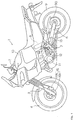
- Fig. 1 is a complete left side view of a two wheel drive motorcycle of this invention
- Fig. 2 is a fragmentary right side view of the motorcycle, showing the vicinity of the front wheel.
- a dual purpose type motorcycle 1 for on-road and off-road purpose
- a head pipe (not shown) provided at the forward end of a main frame
- a steering section provided with a handle 2 at the top and front forks 3 at the bottom:
- the front wheel 4 is mounted on an axle fixed near the lower end of the front forks 3 adapted to be rotatable through the operation of the handle 2.
- the main frame is provided at the rear end with a pair of right and left rear arm brackets 5 extending downwardly: on the rear arm brackets are supported the forward ends of rear arms 6 by a pivot shaft 7; between the rear arms 6 and the main frame is interposed a rear cushion 8 comprised of the combination of a spring and an oil damper: and a rear wheel 9 is mounted on an axle fixed for adjustment near the rear ends of the rear arms 6 supported for vertical swinging movement on the vehicle body through the rear cushion 8.
- a fuel tank in a straddle fashion; downwardly of the fuel tank 10 is provided an engine 11; from a crankcase of the engine 11 is protruded sidewardly an output shaft 12 of a transmission; and a chain 13 is stretched over the sprocket fixed to the output shaft 12 and a sprocket fixed to a hub 90 of the rear wheel 9.
- an oil pump 14 In a space of the motorcycle 1 surrounded by the engine 11, the rear cushion 8, and the rear arms 6, is disposed an oil pump 14; and a chain 15 is stretched over a sprocket fixed to the input shaft of the oil pump 14 and a sprocket (different from the one with the chain 15) fixed to the output shaft 12 so that the oil pump 14 can be operated in association with the rotation of the output shaft 12.
- a disc brake 16 comprised of a caliper 16a and a brake disc 16b
- an oil motor 17 located rearwardly of the front forks 3 and within the radius of a hub 40 of the front wheel 4; and the oil pump 14 and the oil motor 17 are in communication with each other through an oil feed hose 18 so that the oil motor 17 can be driven through oil pressure generated by the oil pump 14.
- Fig. 3 shows a mechanism for driving the front and rear wheels 4, 9 in the motorcycle 1 with the oil pump 14 and the oil motor 17 disposed as described above.
- the other sprocket 22 is connected to a sprocket 24 fixed to an input shaft 14a of the oil pump 14 through a chain 15 so that the rotation of the output shaft 12 causes the oil pump 14 to operate through the sprocket 22, the chain 15, and the sprocket 24.
- an oil circuit comprised of an oil feed hose 18; in the middle of the oil circuit are provided an oil filter 26 and an accumulator 27, and formed a bypass passage 29 provided with an oil pressure regulating valve 28 as well as a bypass passage 31 provided with an oil motor drive switching valve 30 for turning on and off the oil motor 17.
- the driving force of the oil motor 17 can be adjusted by turning on the oil motor drive switching valve 30 (closed) so as to regulate the pressure of the oil flowing from the oil pump 14 into the oil motor 17 through the oil pressure regulating valve 28, and the operation of the oil motor 17 can be stopped by turning off the oil motor drive switching valve 30 (opened) so as to release the oil pressure from the bypass passage 31.
- the front wheel can be forced to stop during turning when the oil motor drive switching valve 30 is turned on (closed) and the opening/closing valve 35 is closed.
- This function is utilized as a brake with the result that the disc brake 16 can be eliminated.
- the oil pump 14 and the oil motor 17 in this embodiment are installed to the motorcycle, with structures described below, respectively.
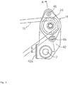
- Fig. 4 is a fragmentary side view of the motorcycle, showing the oil pump 14 being mounted
- Fig. 5 is a view taken along line A - A of Fig. 4, showing the mounting structure of the oil pump 14.
- Fig. 5 on the pivot shaft 7 passing through the protruding portion of the crankcase 11a and extending across the right and left frames (rear arm brackets), at both sides thereof, are mounted the forward ends of the right and left rear arms 6, for rotation through collars 41, respectively.
- the oil pump 14 are mounted to the pump mounting brackets 42, 43 with bolts 44, 45 so that it is installed, as shown in Fig. 1, in the space surrounded by the the engine 11, the rear cushion 8, and the rear arms 6 so as to be secured upwardly of the pivot shaft 7 on the rear arms 6.
- the oil pump 14 is installed in the space surrounded by the engine 11, the rear cushion 8, and the rear arms 6, it can be located close to the center of gravity of the vehicle with little influence on the weight distribution of the vehicle.
- the pump mounting bracket 42, 43 can be secured through a simple means of just fitting onto the pivot shaft 7, and the contact portions 42a, 43a formed at the lower forward edges of the pump mounting bracket 42, 43 are adapted to be set against the rear walls of the crankcase 11a, the pump bracket 42, 43 will not be turned when the tension of the chain 15 is exerted on the oil pump 14, so that the oil pump 14 can be secured reliably.
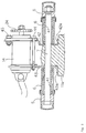
- Fig. 6 shows an installation structure of the oil motor 17.
- a hub body 40a of the front wheel 4 mounted for rotation on an axle 51 fixed to the right and left front forks 3 is formed an annular space 40b with a center at the axle 51 when viewed in profile, with one side (the right side) open, and on the other side (the left side) of the hub body 40a is fixed the brake disc 16b with bolts 52.
- the open side (the right side) of the annular space 40b of the hub 40 is covered by a cap member 40c fixed to the axle 51; between the periphery of the cap member 40c and the hub body 40a is provided a seal member 54 for filling the gap; and on the cap member 40c and rearwardly of the front forks 3 is mounted the oil motor 17 so as to penetrate the cap member 40c.
- the oil motor 17 is of an axial plunger type known as what is called a swash plate motor. It has an internal structure (not shown) in which a plurality of circularly disposed plungers are in a driving contact with a plate disposed oblique to the axial line of the plungers, and expanded and contracted in due order at certain intervals through oil pressure so that the axial movement of the plungers is converted to a rotary movement through the plate in engagement with the plungers.
- a section 17a enclosing a plurality of plungers and a section 17b having the protruded output shaft 17c are coupled at an obtuse angle in plan view to each other.
- the oil motor 17 mounted to the hub 40 of the front wheel 4 is a swash plate motor in which the section 17a and the section 17b are coupled at an obtuse angle to each other so that the oil motor 17 can be compactly disposed radially as close as possible to the axle 51 with respect to the front wheel, without interference between the protruded section 17a and the front forks 3 in the longitudinal direction.
- the diameter of the hub 40 itself can be diminished and the weight of the related parts can be decreased, reducing the inertial mass around the steering shaft.
- the oil motor 17 is enclosed partially in the hub 40 so that the hub 40 itself can be made as compact as the conventional front wheel hub with respect to the crosswise direction, without getting thicker and bulky, and in spite of the section 17a of the oil motor protruding outwardly from the hub 40, the protruded section 17a is located rearwardly of and close to the front forks 3 so that the section 17a can be protected by the front forks 3 from obstacles coming to the front when running.
- assembly work of the front wheel and the oil motor to the vehicle can be performed easily, the oil motor can be installed compactly without increasing the size of the hub section of the front wheel too much, the weight of the related parts can be decreased, reducing the inertial mass around the steering shaft, and the oil motor can be protected adequately from obstacles during running.
Landscapes
- Engineering & Computer Science (AREA)
- Chemical & Material Sciences (AREA)
- Combustion & Propulsion (AREA)
- Transportation (AREA)
- Mechanical Engineering (AREA)
- Automatic Cycles, And Cycles In General (AREA)
- Arrangement Of Transmissions (AREA)
- Motor Power Transmission Devices (AREA)
Applications Claiming Priority (3)
| Application Number | Priority Date | Filing Date | Title |
|---|---|---|---|
| JP34674295 | 1995-12-13 | ||
| JP34674295A JP3549074B2 (ja) | 1995-12-13 | 1995-12-13 | 全輪駆動式自動二輪車 |
| JP346742/95 | 1995-12-13 |
Publications (3)
| Publication Number | Publication Date |
|---|---|
| EP0779205A2 true EP0779205A2 (de) | 1997-06-18 |
| EP0779205A3 EP0779205A3 (de) | 1998-04-29 |
| EP0779205B1 EP0779205B1 (de) | 2002-10-02 |
Family
ID=18385511
Family Applications (1)
| Application Number | Title | Priority Date | Filing Date |
|---|---|---|---|
| EP96120091A Expired - Lifetime EP0779205B1 (de) | 1995-12-13 | 1996-12-13 | Motorrad mit Zweiradantrieb |
Country Status (4)
| Country | Link |
|---|---|
| US (1) | US5873428A (de) |
| EP (1) | EP0779205B1 (de) |
| JP (1) | JP3549074B2 (de) |
| DE (1) | DE69624078T2 (de) |
Cited By (5)
| Publication number | Priority date | Publication date | Assignee | Title |
|---|---|---|---|---|
| WO2002028698A1 (en) | 2000-10-02 | 2002-04-11 | Christini Technologies, Inc. | Two-wheel drive two-wheeled vehicle |
| WO2003070554A1 (en) * | 2002-02-22 | 2003-08-28 | öHLINS RACING AB | Arrangement and device for driving a vehicle wheel, preferably a motorcycle front wheel |
| US7328766B2 (en) | 1996-04-26 | 2008-02-12 | Christini Technologies, Inc. | Two-wheel drive two-wheeled vehicle |
| EP1151913A4 (de) * | 1999-11-08 | 2009-03-25 | Yamaha Motor Co Ltd | Fahrrad mit vorder und hinterradantrieb |
| US8056693B2 (en) | 2000-08-03 | 2011-11-15 | Christini Technologies, Inc. | Two-wheel drive two-wheeled vehicle |
Families Citing this family (22)
| Publication number | Priority date | Publication date | Assignee | Title |
|---|---|---|---|---|
| JP4460145B2 (ja) * | 2000-08-30 | 2010-05-12 | 本田技研工業株式会社 | 電気自動車におけるインホイール変速機の制御装置 |
| US7438147B2 (en) * | 2003-04-02 | 2008-10-21 | Yamaha Hatsudoki Kabushiki Kaisha | Transmission for off-road vehicle |
| US7147075B2 (en) * | 2003-04-02 | 2006-12-12 | Yamaha Hatsudoki Kabushiki Kaisha | Engine arrangement for off-road vehicle |
| US7506712B2 (en) * | 2003-04-02 | 2009-03-24 | Yamaha Hatsudoki Kabushiki Kaisha | Off road vehicle with air intake system |
| US7510199B2 (en) * | 2003-04-02 | 2009-03-31 | Yamaha Hatsudoki Kabushiki Kaisha | Off-road vehicle with wheel suspension |
| US7357211B2 (en) * | 2003-04-02 | 2008-04-15 | Yamaha Hatsudoki Kabushiki Kaisha | Steering system for off-road vehicle |
| US7367417B2 (en) * | 2003-04-02 | 2008-05-06 | Yamaha Hatsudoki Kabushiki Kaisha | Floor arrangement for off-road vehicle |
| US7287619B2 (en) * | 2003-04-02 | 2007-10-30 | Yamaha Hatsudoki Kabushiki Kaisha | Air intake system for off-road vehicle |
| US7650959B2 (en) * | 2003-04-02 | 2010-01-26 | Yamaha Hatsudoki Kabushiki Kaisha | Frame arrangement for off-road vehicle |
| US7147076B2 (en) * | 2003-04-02 | 2006-12-12 | Yamaha Hatsudoki Kabushiki Kaisha | Drive system for off-road vehicle |
| US20050029031A1 (en) * | 2003-08-04 | 2005-02-10 | Thomas Ralph M. | Vehicle |
| SE526236C2 (sv) | 2003-12-23 | 2005-08-02 | Oehlins Racing Ab | Anordning vid fordon |
| JP2006076543A (ja) * | 2004-09-13 | 2006-03-23 | Yamaha Motor Co Ltd | 鞍乗型車両 |
| JP4495018B2 (ja) * | 2005-03-24 | 2010-06-30 | 本田技研工業株式会社 | 全輪駆動式自動二輪車 |
| SE528841C2 (sv) * | 2005-06-20 | 2007-02-27 | Oehlins Racing Ab | Arrangemang vid motorcykel |
| DE102007006167A1 (de) | 2007-02-07 | 2008-08-14 | Ktm Sportmotorcycle Ag | Fahrzeug |
| US8042641B2 (en) * | 2009-02-09 | 2011-10-25 | Lawson Martin E | All wheel drive motorcycle |
| US8973690B2 (en) | 2010-10-04 | 2015-03-10 | W. Morrision Consulting Group, Inc. | Front wheel energy recovery system |
| CN102582738B (zh) * | 2011-12-01 | 2013-08-07 | 北京邮电大学 | 一种变结构自平衡两轮车 |
| ITUB20155524A1 (it) | 2015-11-12 | 2017-05-12 | Visionar S R L | Sistema di ripartizione di coppia per motoveicoli elettrici a due ruote motrici. |
| IT202000001510A1 (it) | 2020-01-27 | 2021-07-27 | Visionar S R L | Metodo e unita' di controllo per ripartire la trazione in un veicolo a due ruote in linea motorizzate |
| WO2024260565A1 (en) * | 2023-06-23 | 2024-12-26 | Robert Bosch Gmbh | Electric vehicle and method of operating an electric vehicle |
Citations (3)
| Publication number | Priority date | Publication date | Assignee | Title |
|---|---|---|---|---|
| JPS61125974A (ja) | 1984-11-21 | 1986-06-13 | 境 紀之 | 全輪駆動二輪車 |
| JPH01273782A (ja) | 1988-04-25 | 1989-11-01 | Kichisaburo Komoritani | 2輪車の油圧式前輪駆動 |
| JPH0592794A (ja) | 1991-03-01 | 1993-04-16 | Kawasaki Heavy Ind Ltd | 自動2輪車の2輪駆動装置 |
Family Cites Families (5)
| Publication number | Priority date | Publication date | Assignee | Title |
|---|---|---|---|---|
| US4157739A (en) * | 1976-04-19 | 1979-06-12 | Frye Norman V | Motorcycle |
| FR2589213B1 (fr) * | 1985-10-25 | 1990-03-09 | Renault | Dispositif d'entrainement hydrostatique d'une roue |
| US4955451A (en) * | 1988-10-17 | 1990-09-11 | Schaefer Stephen H | Utility vehicle |
| JP3367614B2 (ja) * | 1991-10-17 | 2003-01-14 | 株式会社小松製作所 | ダンプトラックの操舵輪油圧駆動装置 |
| JPH05112155A (ja) * | 1991-10-21 | 1993-05-07 | Honda Motor Co Ltd | 自動車の駆動装置 |
-
1995
- 1995-12-13 JP JP34674295A patent/JP3549074B2/ja not_active Expired - Fee Related
-
1996
- 1996-12-11 US US08/763,828 patent/US5873428A/en not_active Expired - Fee Related
- 1996-12-13 EP EP96120091A patent/EP0779205B1/de not_active Expired - Lifetime
- 1996-12-13 DE DE69624078T patent/DE69624078T2/de not_active Expired - Lifetime
Patent Citations (3)
| Publication number | Priority date | Publication date | Assignee | Title |
|---|---|---|---|---|
| JPS61125974A (ja) | 1984-11-21 | 1986-06-13 | 境 紀之 | 全輪駆動二輪車 |
| JPH01273782A (ja) | 1988-04-25 | 1989-11-01 | Kichisaburo Komoritani | 2輪車の油圧式前輪駆動 |
| JPH0592794A (ja) | 1991-03-01 | 1993-04-16 | Kawasaki Heavy Ind Ltd | 自動2輪車の2輪駆動装置 |
Cited By (8)
| Publication number | Priority date | Publication date | Assignee | Title |
|---|---|---|---|---|
| US6505699B1 (en) | 1996-04-26 | 2003-01-14 | Christini Technologies, Inc. | Two-wheel drive two-wheeled vehicle |
| US7328766B2 (en) | 1996-04-26 | 2008-02-12 | Christini Technologies, Inc. | Two-wheel drive two-wheeled vehicle |
| US7487854B2 (en) | 1996-04-26 | 2009-02-10 | Christini Technologies, Inc. | Two-wheel drive two-wheeled vehicle |
| EP1151913A4 (de) * | 1999-11-08 | 2009-03-25 | Yamaha Motor Co Ltd | Fahrrad mit vorder und hinterradantrieb |
| US8056693B2 (en) | 2000-08-03 | 2011-11-15 | Christini Technologies, Inc. | Two-wheel drive two-wheeled vehicle |
| US8689957B2 (en) | 2000-08-03 | 2014-04-08 | Christini Technologies, Inc. | Two-wheel drive two-wheeled vehicle |
| WO2002028698A1 (en) | 2000-10-02 | 2002-04-11 | Christini Technologies, Inc. | Two-wheel drive two-wheeled vehicle |
| WO2003070554A1 (en) * | 2002-02-22 | 2003-08-28 | öHLINS RACING AB | Arrangement and device for driving a vehicle wheel, preferably a motorcycle front wheel |
Also Published As
| Publication number | Publication date |
|---|---|
| US5873428A (en) | 1999-02-23 |
| DE69624078D1 (de) | 2002-11-07 |
| EP0779205A3 (de) | 1998-04-29 |
| JPH09156570A (ja) | 1997-06-17 |
| EP0779205B1 (de) | 2002-10-02 |
| DE69624078T2 (de) | 2003-08-14 |
| JP3549074B2 (ja) | 2004-08-04 |
Similar Documents
| Publication | Publication Date | Title |
|---|---|---|
| EP0779205B1 (de) | Motorrad mit Zweiradantrieb | |
| DE60116935T2 (de) | Hinterradaufhängungsstruktur für ein Motorrad | |
| EP0822136A2 (de) | Hilfsantrieb für Fahrräder | |
| EP0758050B1 (de) | Struktur zur Anordnung/Positionierung von Anlasser für schwenkbaren Verbrennungsmotor | |
| JP4409638B2 (ja) | スクータ用アンチロックブレーキ装置 | |
| EP1151913A1 (de) | Fahrrad mit vorder und hinterradantrieb | |
| JP2657661B2 (ja) | 自動二輪車の車体下部構造 | |
| JP2523198B2 (ja) | 無端ベルトを備えた車両 | |
| JP2852542B2 (ja) | 自動2輪車における前輪駆動装置 | |
| JP2617208B2 (ja) | パワーステアリング装置 | |
| JP2592850B2 (ja) | 後二輪を有する車両のハブ取付け装置 | |
| JP2955292B2 (ja) | 後二輪を有するチェーン駆動形車両 | |
| JP3821680B2 (ja) | 草刈り機 | |
| JP3620076B2 (ja) | スクータ型小型車両 | |
| JP3564716B2 (ja) | トラクタのデフ装置 | |
| JPH0521515Y2 (de) | ||
| JPH03200494A (ja) | 自動二輪車の前後輪操向装置 | |
| JP3719529B2 (ja) | クローラ式走行装置 | |
| JP3640733B2 (ja) | 全輪駆動車両 | |
| JPS63115927A (ja) | ブレ−キ装置 | |
| JPS635939Y2 (de) | ||
| JPH032038Y2 (de) | ||
| JP2726448B2 (ja) | 車両用変速装置における変速リンク機構 | |
| JP3843542B2 (ja) | 産業車両の操舵トルク伝達装置 | |
| JP2000229596A (ja) | 全輪駆動式車両 |
Legal Events
| Date | Code | Title | Description |
|---|---|---|---|
| PUAI | Public reference made under article 153(3) epc to a published international application that has entered the european phase |
Free format text: ORIGINAL CODE: 0009012 |
|
| AK | Designated contracting states |
Kind code of ref document: A2 Designated state(s): DE FR IT |
|
| PUAL | Search report despatched |
Free format text: ORIGINAL CODE: 0009013 |
|
| AK | Designated contracting states |
Kind code of ref document: A3 Designated state(s): DE FR IT |
|
| 17P | Request for examination filed |
Effective date: 19981022 |
|
| GRAG | Despatch of communication of intention to grant |
Free format text: ORIGINAL CODE: EPIDOS AGRA |
|
| 17Q | First examination report despatched |
Effective date: 20011128 |
|
| GRAG | Despatch of communication of intention to grant |
Free format text: ORIGINAL CODE: EPIDOS AGRA |
|
| GRAH | Despatch of communication of intention to grant a patent |
Free format text: ORIGINAL CODE: EPIDOS IGRA |
|
| GRAH | Despatch of communication of intention to grant a patent |
Free format text: ORIGINAL CODE: EPIDOS IGRA |
|
| GRAA | (expected) grant |
Free format text: ORIGINAL CODE: 0009210 |
|
| AK | Designated contracting states |
Kind code of ref document: B1 Designated state(s): DE FR IT |
|
| REF | Corresponds to: |
Ref document number: 69624078 Country of ref document: DE Date of ref document: 20021107 |
|
| ET | Fr: translation filed | ||
| PLBE | No opposition filed within time limit |
Free format text: ORIGINAL CODE: 0009261 |
|
| STAA | Information on the status of an ep patent application or granted ep patent |
Free format text: STATUS: NO OPPOSITION FILED WITHIN TIME LIMIT |
|
| 26N | No opposition filed |
Effective date: 20030703 |
|
| PGFP | Annual fee paid to national office [announced via postgrant information from national office to epo] |
Ref country code: IT Payment date: 20061231 Year of fee payment: 11 |
|
| PG25 | Lapsed in a contracting state [announced via postgrant information from national office to epo] |
Ref country code: IT Free format text: LAPSE BECAUSE OF NON-PAYMENT OF DUE FEES Effective date: 20071213 |
|
| REG | Reference to a national code |
Ref country code: FR Ref legal event code: PLFP Year of fee payment: 20 |
|
| PGFP | Annual fee paid to national office [announced via postgrant information from national office to epo] |
Ref country code: DE Payment date: 20151211 Year of fee payment: 20 |
|
| PGFP | Annual fee paid to national office [announced via postgrant information from national office to epo] |
Ref country code: FR Payment date: 20151221 Year of fee payment: 20 |
|
| REG | Reference to a national code |
Ref country code: DE Ref legal event code: R071 Ref document number: 69624078 Country of ref document: DE |