EP0779482B2 - Circuit frigorifique - Google Patents
Circuit frigorifique Download PDFInfo
- Publication number
- EP0779482B2 EP0779482B2 EP96119355A EP96119355A EP0779482B2 EP 0779482 B2 EP0779482 B2 EP 0779482B2 EP 96119355 A EP96119355 A EP 96119355A EP 96119355 A EP96119355 A EP 96119355A EP 0779482 B2 EP0779482 B2 EP 0779482B2
- Authority
- EP
- European Patent Office
- Prior art keywords
- capillary tube
- refrigeration cycle
- refrigerant
- capillary
- capillary tubes
- Prior art date
- Legal status (The legal status is an assumption and is not a legal conclusion. Google has not performed a legal analysis and makes no representation as to the accuracy of the status listed.)
- Expired - Lifetime
Links
Images


Classifications
-
- F—MECHANICAL ENGINEERING; LIGHTING; HEATING; WEAPONS; BLASTING
- F25—REFRIGERATION OR COOLING; COMBINED HEATING AND REFRIGERATION SYSTEMS; HEAT PUMP SYSTEMS; MANUFACTURE OR STORAGE OF ICE; LIQUEFACTION SOLIDIFICATION OF GASES
- F25B—REFRIGERATION MACHINES, PLANTS OR SYSTEMS; COMBINED HEATING AND REFRIGERATION SYSTEMS; HEAT PUMP SYSTEMS
- F25B1/00—Compression machines, plants or systems with non-reversible cycle
-
- F—MECHANICAL ENGINEERING; LIGHTING; HEATING; WEAPONS; BLASTING
- F25—REFRIGERATION OR COOLING; COMBINED HEATING AND REFRIGERATION SYSTEMS; HEAT PUMP SYSTEMS; MANUFACTURE OR STORAGE OF ICE; LIQUEFACTION SOLIDIFICATION OF GASES
- F25B—REFRIGERATION MACHINES, PLANTS OR SYSTEMS; COMBINED HEATING AND REFRIGERATION SYSTEMS; HEAT PUMP SYSTEMS
- F25B41/00—Fluid-circulation arrangements
- F25B41/30—Expansion means; Dispositions thereof
- F25B41/37—Capillary tubes
-
- F—MECHANICAL ENGINEERING; LIGHTING; HEATING; WEAPONS; BLASTING
- F25—REFRIGERATION OR COOLING; COMBINED HEATING AND REFRIGERATION SYSTEMS; HEAT PUMP SYSTEMS; MANUFACTURE OR STORAGE OF ICE; LIQUEFACTION SOLIDIFICATION OF GASES
- F25B—REFRIGERATION MACHINES, PLANTS OR SYSTEMS; COMBINED HEATING AND REFRIGERATION SYSTEMS; HEAT PUMP SYSTEMS
- F25B41/00—Fluid-circulation arrangements
- F25B41/30—Expansion means; Dispositions thereof
- F25B41/385—Dispositions with two or more expansion means arranged in parallel on a refrigerant line leading to the same evaporator
-
- F—MECHANICAL ENGINEERING; LIGHTING; HEATING; WEAPONS; BLASTING
- F25—REFRIGERATION OR COOLING; COMBINED HEATING AND REFRIGERATION SYSTEMS; HEAT PUMP SYSTEMS; MANUFACTURE OR STORAGE OF ICE; LIQUEFACTION SOLIDIFICATION OF GASES
- F25B—REFRIGERATION MACHINES, PLANTS OR SYSTEMS; COMBINED HEATING AND REFRIGERATION SYSTEMS; HEAT PUMP SYSTEMS
- F25B2500/00—Problems to be solved
- F25B2500/01—Geometry problems, e.g. for reducing size
Definitions
- the present invention relates to a refrigeration cycle, and more particularly to a refrigeration cycle connecting a compressor, a condenser, an expansion device, and an evaporator in a loop by piping.
- the present invention concerns a refrigeration cycle according to the preamble of present claim 1.
- Such a refrigeration cycle is already known from the document JP-A-06 159 865 .
- the compressor used in refrigeration cycle is composed of, as disclosed in Japanese Laid-open Patent 62-298680 and others, a compressive mechanism filling an enclosed container with such mixed refrigerant and oil for compressing by sucking refrigerant, an oil pump for feeding the oil into machine sliding parts, and a motor for driving them by drive shaft.
- the refrigeration cycle was composed by using refrigerant such as chlorofluorocarbons (CFCs) or R12 and designated hydrochlorofluorocarbons (HCFCs) or R22.
- CFCs chlorofluorocarbons
- HCFCs hydrochlorofluorocarbons
- the specific CFCs are chemically stable, and free from flammability and toxicity as compared with hitherto known refrigerants such as sulfur dioxide and methyl chloride, and are widely applied as ideal refrigerants and have been used for many years.
- chlorine atoms contained in the molecules of specific CFCs are recognized to induce destruction of the ozone layer, and development and use of alternative refrigerants not containing chlorine atoms have been attempted.
- refrigerant for example, a chlorine-free refrigerant such as hydrofluorocarbon has been proposed (Hydraulic and Pneumatic Technology, June 1994, Nippon Kogyo Shuppan).
- R134a is used as an alternative refrigerant.
- the alternative refrigerant is not expected to have an excellent lubricity as in the conventional specific CFCs. Accordingly, as the oil to be contained in the enclosed container, an oil compatible with the alter native refrigerant is particularly required.
- the oil contained in the enclosed container is stirred by the alternative refrigerant discharged from the compressive mechanism into the enclosed container, and is further stirred by rotor of the motor. At this time, if the oil is compatible with the alternative refrigerant, the oil is stirred well with the refrigerant discharged into the enclosed container, and permeates into narrow gaps in the sliding parts of the machines. Therefore, together with the effects of supply of oil by oil pump, the lubricating performance is enhanced.
- an ester derivative synthetic oil is used as disclosed in Japanese Laid-open Patent 6-235570 .
- ester oil as the oil compatible with the alternative refrigerant. If moisture invades when enclosing the refrigerant piping, or moisture is formed after enclosing due to some reason, the ester oil is hydrolyzed by the moisture, and produces fatty acid. The fatty acid corrodes the parts in the piping, forms metal soap and produces sludge.
- the ester oil is low in stability, and therefore foreign matter is likely to be dissolved and mixed in when the temperature is raised, or foreign matter is likely to precipitate when the temperature is lowered.
- the above Japanese Laid-open Patent 6-235570 discloses a refrigeration cycle characterized by solving the problems of faulty flow of refrigerant or clogging in the capillary tube, by capturing the foreign matter by installing a filter immediately at the upstream side in the flow direction of the refrigerant in the capillary tube in the midst of the refrigerant piping.
- the above filter structure is complicated and expensive, and it cannot cope with the defect of precipitation due to temperature drop at the outlet of the capillary tube and immediate deposit of the precipitates.
- the filter In the refrigeration cycle operated by the heat pump, if the flow direction of refrigerant is reverse in changeover of heating and cooling, the filter must be provided at both sides of the capillary tube, which further adds to the cost.
- the present invention thus concerns a refrigeration cycle as defined in the appended claims.
- the refrigeration cycle of the invention comprises a compressor, a condenser, an expansion device, and an evaporator connected in a loop by piping, using an alternative refrigerant, in which the expansion device has a capillary tube and a junction for connecting the capillary tube and piping, the inside diameter of the junction is larger than the inside diameter of the capillary tube and the capillary tube projects freely into the junction. Foreign matter that may impede passing of refrigerant deposits aggressively in the inside space of the connection pipe and an outer surface of the free projecting end of the capillary tube.
- the junction has a slope decreasing gradually in the inside diameter from the piping side to the capillary tube side.
- This slope forms a wide space at the end portion of either inlet or outlet part of the capillary tube, regardless of the direction in which the refrigerant flows.
- the depositing foreign matter does not affect the main flow of the refrigerant in the capillary tube or junction because of the wide space in the junction. Therefore, the refrigerating function of the refrigerating cycle is stable for a long period, and the reliability is enhanced.
- the above effects are obtained only by the improvement of the duct shape of each junction of the capillary tube and piping. Hence, the structure is simple and inexpensive.
- the end portion at the inlet or outlet of the capillary tube projects freely into the junction of larger diameter than the end portion, and the flow of refrigerant is stagnant between the outer surface of the protrusion and the wide inner surface of the junction of the piping side, so that much foreign matter deposits aggressively on the outer surface of the protrusion and inside of the junction and in the space between them.
- the depositing foreign matter has no effect on the main flow of the refrigerant in the capillary tube and junction.
- clogging of capillary tube can be prevented for a longer period. Therefore, the refrigerating function of the refrigerating cycle is stable for a long period, and the reliability is enhanced.
- the above effects are obtained by the improvement of the connection state of each junction of the capillary tube and piping.
- the junction possesses an oleophilic treated inner surface.
- the junction has a slope gradually decreasing in inside diameter from the piping side to the capillary tube side.
- the structure is not complicated, and the actions and effects as above are obtained.
- the projecting end of the capillary tube is particularly preferred to be opened obliquely to the axial line of the capillary tube.
- the opening area of the piping side of the capillary tube to the wide space side is large, and therefore the foreign matter is less likely to be caught in the opening of the projecting end at the inlet and outlet of the capillary tube, so that foreign matter deposit preventive function at the capillary tube inlet and outlet may be further enhanced.
- a hole is provided in the peripheral wall of the projecting end of the capillary tube.
- the capillary tube for composing the expansion device comprises plural capillary tubes differing at least in the inside diameter or length, and it is particularly preferred that these plural capillary tubes are connected parallel.
- foreign matter clogging occurs in the sequence of difficulty of flow of refrigerant (that is, from the capillary tube having smaller inside diameter or longer capillary tube). Therefore, early clogging of the entire capillary tubes is prevented, and a normal function is maintained for a long period. That is, only the number of capillary tubes is increases, and in proportion to the increase in the number of capillary tubes, the required diameter of capillary tubes is smaller or shorter in length, so that the structure is not particularly complicated.
- a slope connected in batch with each capillary tube gradually increasing in the inside diameter from the piping side to each capillary tube side, is formed in the junction of the plural capillary tubes and piping.
- each capillary tube should be projected into the slope.
- the projecting ends of the capillary tubes are particularly preferred to be opened obliquely to their axial line.
- a hole should be provided in the peripheral wall of the projecting end of capillary tube.
- the capillary tube for composing the expansion device comprises plural capillary tubes, and each one of the plural capillary tubes has an valve.
- the capillary tubes in use can be assembled into one by opening or closing the valves, and the capillary tubes in use can be sequentially changed over depending on the degree of clogging of the capillary tubes with foreign matter. By thus constituting, early clogging of the entire capillary tubes is prevented.
- the changeover control is effected by the method of utilizing the control means for operation control of the refrigeration cycle itself, and a normal function can be maintained for a long period without particularly complicating the structure.
- a different refrigeration cycle of the invention comprises a compressor, a condenser, an expansion device, and an evaporator connected in a loop by piping, using an alternative refrigerant, and further comprises a heat pump changeover valve.
- the expansion device comprises plural capillary tubes, and a junction for connecting the capillary tubes and a piping, and the plural capillary tubes have individually a one-way valve, and are connected so that the direction of the one-way valves may be opposite to each other.
- the expansion device possesses plural capillary tubes, and the plural tubes are connected in series through the connection pipes provided among them.
- the connection pipes have a larger inside diameter than the inside diameter of the capillary tubes. Since the inside diameter of the connection pipes is wider, the refrigerant is caused to flow stagnantly, and foreign matter can be deposited by force to be removed from the refrigerant, so that adhesion to the capillary tubes can be prevented.
- the capillary tubes can be divided by the connection pipes so that the foreign matter may not affect the flow of the refrigerant, and the actual length of capillary tubes is shortened to several times smaller than the required length, so that foreign matter may hardly deposit on the capillary tubes.
- the inner surface of the capillary tubes should have a smooth layer.
- the smoothness of the smooth layer in the inner surface of the capillary tube foreign matter is less likely to be caught or adhered.
- the inner surface of the capillary tubes for composing the expansion device should have a parting process surface treated for parting. Therefore, foreign matter is less likely to deposit on the parting surface of the inner surface of the capillary tube.
- the inner surface of the capillary tubes for composing the expansion device should have a hydrophilic layer treated for hydrophilic property. Therefore, deposit of oily foreign matter can be prevented by hydrophilic property of the inner surface of the capillary tubes.
- the inside diameter of the junction of the capillary tubes for composing the expansion device and the piping should be larger than the inside diameter of the capillary tubes, and moreover the inner surface of the junction should have an oleophilic surface processed by oleophilic treatment.
- Fig. 1 is a schematic diagram of refrigeration cycle of heat pump type.
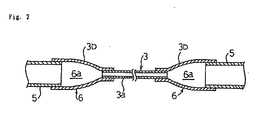
- Fig. 2 is a sectional view showing a connection structure, which does not form part of the present invention, of piping and expansion device in Fig. 1.
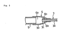
- Fig. 3 is a sectional view showing a connection structure of piping and expansion device in a first embodiment of the invention.
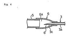
- Fig. 4 is a sectional view showing a connection structure of piping and expansion device in a second embodiment of the invention.
- Fig. 5 is a sectional view showing a connection structure of piping and expansion device in a third embodiment of the invention.
- Fig. 6 is a sectional view showing a connection structure of piping and expansion device not forming part of the invention.
- Fig. 7 is a sectional view showing a connection structure of piping and expansion device not forming part of the invention.
- Fig. 8 is a sectional view showing a connection structure of piping and expansion device in a fourth embodiment of the invention, and a block diagram of control means.
- Fig. 9 is a sectional view showing a connection structure of piping and expansion device in an fifth embodiment of the invention.
- Fig. 10 is a sectional view showing a connection structure of piping and expansion device in an sixth embodiment of the invention.
- Fig. 11 is a sectional view showing part of capillary tubes for composing an expansion device in a seventh embodiment of the invention.
- Fig. 12 is a sectional view showing part of capillary tubes for composing an expansion device in a eighth embodiment of the invention.
- Fig. 13 is a sectional view showing part of capillary tubes for composing an expansion device in an ninth embodiment of the invention.
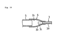
- Fig. 14 is a sectional view showing a connection structure of piping and expansion device of the invention.
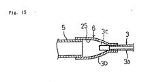
- Fig. 15 is a sectional view showing a connection structure of piping and expansion device in the first embodiment of the invention.
- FIG. 1 A schematic diagram of refrigeration cycle of heat pump type is illustrated in Fig. 1.
- the refrigeration cycle is composed by connecting a compressor 1, a condenser 2, an expansion device 3, and an evaporator 4 in a loop by means of a piping 5, using an alternative refrigerant.
- a synthetic oil compatible with the alternative refrigerant whether this refrigeration cycle is operated by changing over between cooling operation and heating operation, foreign matter mixed in the refrigerant may adhere to the inlet or outlet of the capillary tubes.
- a four-way valve (not shown) for changing over between cooling operation and heating operation.
- the refrigerant flows in the direction indicated by arrow into the condenser 2, expansion device 3 and evaporator 4 as shown in Fig. 1.
- the refrigerant flows reversely.
- the condenser 2 in cooling operation functions as evaporator
- the evaporator 4 functions as condenser.
- the synthetic oil compatible with the alternative refrigerant for example, an ester oil
- the foreign matter mixing in or precipitating in the refrigerant is likely to deposit on the end portions at the inlet and outlet of the capillary tubes 3a for composing the expansion device 3, in particular, on the inner surface.
- flow of refrigerant is blocked early, or clogging occurs, and thereby the function of the refrigeration cycle is often lowered early.
- FIG. 2 A connection structure, which does not form part of the present invention, of the piping 5 and expansion device 3 is shown in Fig. 2.
- a slope 6 decreasing gradually in inside diameter from the piping 5 side to the capillary tube 3a side is provided at the junction 3b of the capillary tube 3a and piping 5 forming the expansion device 3.
- This slope 6 forms a wide space 6a at both ends at the inlet and outlet of the capillary tube 3a regardless of the direction of flow of the refrigerant. If foreign matter deposits on the inner surface of the space 6a, the depositing foreign matter does not affect the main flow of the refrigerant in the capillary tube 3a and junction 3b because the space of the junction 3b is wide.
- the junction 3b is formed separately, not integrated with the piping 5 and capillary tube 3a. Therefore, the piping 5, capillary tube 3a and junction 3b are mutually linked together, and the slope shape of the junction 3b can be easily formed by processing of an independent part. Also in the embodiment, this independent junction 3b is fitted externally to the end of the piping 5 and capillary tube 3a, and therefore this connection structure itself can expand the space of the junction 3b having the slope 6, and the effect of the deposit of foreign matter on the flow of refrigerant can be reduced, which is advantageous for long-term stability of the function of the refrigeration cycle.
- the junction 3b can be also formed integrally with one or both of the piping 5 and capillary tube 3a.
- the junction 3b is, together with the piping 5 and capillary tube 3a, made of copper as usual, and they can be joined by brazing. Other material and joining structure may be also possible.
- FIG. 3 A connection structure of piping and expansion device in a first embodiment is shown in Fig. 3. This embodiment is based on the structure of the above embodiment, and same members are identified with same reference numerals, and duplicate explanations are omitted.
- the capillary tube 3a forming the expansion device 3 projects to the inside of the junction 3b at the piping 5 side.
- the end portion at the inlet or outlet of the capillary tube 3a projects to the inside of the junction 3b having a wide space 6a larger in diameter than the end portion, and the flow of the refrigerant is stagnant in the portion 6b between the outer side of the projecting end portion 3c and the inner side of the wide junction 3b at the piping 5 side.
- connection structure of the embodiment is not limited to the constitution shown in Fig. 1, but, for example, the end portion of the capillary tube 3a of small diameter may project from the end plate closing the end portion of the piping 5 of larger diameter to the inner side of the piping 5.
- the intrinsic actions and effects of the embodiment are exhibited, and the function of the refrigeration cycle can be stabilized for a long period to a certain extent.
- the inside of the junction 3b of the expansion device 3 has an oleophilic treated layer 25.
- Oily foreign matter is forced to deposit on oleophilic inner surface and the inside of the slope 6 having a wide space 6b, so that foreign matter may hardly deposit on the inside of the capillary tube 3a and other parts. Therefore, the reliability of the refrigeration cycle is enhanced. Moreover, it is inexpensive without particularly complicating the structure. Oleophilic treatment is done by film coating with alcoholic resin or the like.
- the refrigerant may flow in cooling operation or heating operation, deposit of foreign matter at the end portion at the inlet or outlet of the capillary tube is prevented, and blocking of flow of refrigerant and closing of capillary tube can be prevented.
- the refrigeration function of the refrigeration cycle can be stabilized for a long period, and the reliability is enhanced.
- the structure is not particularly complicated, it is also inexpensive.
- a second embodiment is based on the first embodiment, and same members are identified with same reference numerals, and the characteristic points of the embodiment are described below.
- a connection structure of piping and expansion device in the embodiment is shown in Fig. 4.
- a projecting end 3c of the capillary tube 3a is opened obliquely to the axial line of the capillary tube 3a, and the obliquely opened projecting end 3c projects to the inside of the junction 3b.
- the opening area of the capillary tube 3a to the wide space 6a side of the piping 5 side is wider, so that foreign matter is hardly caught in the opening of the projecting end 3c at the inlet or outlet of the capillary tube 3a.
- the preventive effect of deposit of foreign matter at the inlet or outlet of the capillary tube 3a is further enhanced.
- the embodiment is not always limited to the constitution of the first embodiment.
- a third embodiment is based on the first embodiment, and same members are identified with same reference numerals, and the characteristic points of the embodiment are described below.
- a connection structure of piping and expansion device in the embodiment is shown in Fig. 5.
- a hole 3b is formed in the peripheral wall of the projecting end 3c of the capillary tube 3a.
- FIG. 6 A connection structure of piping and expansion device is shown in Fig. 6.
- the capillary tube for composing the expansion device 3 plural capillary tubes differing in inside diameter are installed.
- three capillary tubes 3e, 3f, 3g project to the inside of the junction 3 and are connected.
- the capillary tubes are clogged sequentially from the one 3g smallest in inside diameter where the refrigerant flows most hardly, and early clogging of the entire capillary tubes 3e to 3g is prevented, so that the normal function can be maintained for a longer period.
- the junction 3b of the plural capillary tubes 3e, 3f, 3g and the piping 5 has a slope 7 gradually increasing in the inside diameter from the piping 5 side to the side of the capillary tubes 3e, 3f, 3g.
- the junction 3b has a wider space 7a than the piping 5 owing to this slope 7.
- FIG. 7 A connection structure of piping and expansion device is shown in Fig. 7.
- Fig. 7 instead of the plural capillary tubes differing in diameter in the previous example, plural capillary tubes 3h, 3i, 3j differing in length are connected in parallel.
- the capillary tubes are clogged sequentially from the one 3h largest in length where the refrigerant flows most hardly, and early clogging of the entire capillary tubes 3h, 3i, 3j is prevented, so that the normal function can be maintained for a longer period.
- FIG. 8 A connection structure of piping and expansion device in a fourth embodiment is shown in Fig. 8.
- plural capillary tubes 3k, 3m, 3n composing the expansion device 3 respectively possess valves 8 to 10, and are connected to the piping 5.
- opening or closing of the valves 8 to 10 opening or closing of the three capillary tubes 3k, 3m, 3n to be used is changed over sequentially. This constitution prevents early clogging of the entire capillary tubes 3k, 3m, 3n.
- Changeover of the valve 8 is controlled by control means for operation control of the refrigeration cycle itself, for example, by microcomputer MC as shown in Fig. 8 (b), so that a normal function can be maintained for a long period without particularly complicating the structure.
- the microcomputer MC every time a clogging signal is received either automatically or manually, the microcomputer MC sequentially changes over the valves 8 to 10, thereby changing over the capillary tubes 3k, 3m, 3n to be used.
- the microcomputer MC can obtain a clogging signal automatically by judging the passing resistance of refrigerant in the capillary tubes 3k, 3m, 3n being used by an internal function for detecting an abnormal pressure rise of refrigerant or the like.
- FIG. 9 A connection structure of piping and expansion device in an fifth embodiment is shown in Fig. 9.
- This embodiment is to replace the fourth embodiment, and belongs to the refrigeration cycle having a heat pump changeover valve same as shown in Fig. 1.
- the expansion device 3 possesses capillary tubes 3p, 3q provided with one-way valves 11, 12 respectively, and these two capillary tubes 3p, 3q are connected parallel so that the direction of the mutual one-way valves 11, 12 may be opposite to each other.
- cooling operation and heating operation the flow direction of refrigerant is mutually opposite, and corresponding to this, by the flow direction control by the one-way valves 11, 12, the passing capillary tube of refrigerant is changed over in cooling operation and heating operation.
- FIG. 10 A connection structure of piping and expansion device in an sixth embodiment is shown in Fig. 10.
- This embodiment is based on the refrigeration cycle shown in Fig. 1.
- plural capillary tubes for composing the expansion device 3 for example, two capillary tubes 3r, 3s are connected in series through a connection pipe 13 provided between them, and the inside diameter of the connection pipe 13 is larger than the inside diameter of the capillary tubes 3r, 3s.
- the refrigerant is caused to stay stagnant in the connection pipe 13 having the larger inside diameter so that foreign matter may deposit by force.
- foreign matter is removed from the refrigerant, and deposit of foreign matter on the capillary tubes can be prevented.
- the capillary tubes can be divided, and the actual length of the capillary tubes may be shortened several times smaller than the required length, and deposit of foreign matter on the capillary tubes can be further prevented. As a result, the reliability of the refrigeration cycle is enhanced. At the same time, it is inexpensive without particularly complicating the structure.
- the embodiment may be also combined with the first to fifth embodiments, and the individual intrinsic actions and effects can be exhibited in such constitution.
- Fig. 11 is a sectional view of part of a capillary tube for composing the expansion device in a seventh embodiment. This embodiment is based on the refrigeration cycle of Fig. 1. As shown in Fig. 11, the inside of the capillary tube 3a for composing the expansion device 3 has a smoothed surface 21.
- Fig. 12 is a sectional view of part of a capillary tube for composing the expansion device in an eighth embodiment.
- This embodiment is based on the refrigeration cycle of Fig.1.
- the inside of the capillary tube 3a for composing the expansion device 3 has a releasing treated layer 22.
- the lubricating or releasing property of the releasing treated layer 2 foreign matter is hardly or adhered to the inside of the capillary tube 3a. Therefore, the reliability of the refrigeration cycle is enhanced.
- Parting process may be done by for example, fluorine coating process, or any other known method.
- Fig. 13 is a sectional view of part of a capillary tube for composing the expansion device in a ninth embodiment.
- This embodiment is based on the refrigeration cycle of Fig.1.
- the inside of the capillary tube 3a for composing the expansion device 3 has a hydrophilic treated layer 23.
- the hydrophilic treated layer 23 is preferably a composition containing, for example, many nitrogen or sulfur atoms, and a nitride treated layer is particularly preferred. It may be also formed by any other known method.
- FIG. 14 A connection structure of piping and expansion device is shown in Fig. 14. This example is based on the constitution of Fig. 1. As shown in Fig. 14, the inside diameter of the junction 3b of the capillary tube 3a for composing the expansion device 3 and piping 5 is set larger than the inside diameter of the capillary tube 3a, and a wide space 6a is provided. Moreover, the inside of the junction 3b has a roughened surface 24. Foreign matter is forced to deposit on the roughened surface 24 and the inside of the slope 6 having the wide space 6a, and foreign matter in the refrigerant can be removed. At the same time, the depositing foreign matter is prevented from having effects on the flow of the refrigerant.
Landscapes
- Engineering & Computer Science (AREA)
- Physics & Mathematics (AREA)
- Mechanical Engineering (AREA)
- Thermal Sciences (AREA)
- General Engineering & Computer Science (AREA)
- Compression-Type Refrigeration Machines With Reversible Cycles (AREA)
- Cooling Or The Like Of Semiconductors Or Solid State Devices (AREA)
- Quick-Acting Or Multi-Walled Pipe Joints (AREA)
- Thermotherapy And Cooling Therapy Devices (AREA)
- Details Of Measuring And Other Instruments (AREA)
- Compressor (AREA)
Claims (14)
- Circuit frigorifique comprenant:un compresseur (1), un condenseur (2), un dispositif de détente (3) et un évaporateur (4),une tubulure (5) reliant ledit compresseur, ledit condenseur, ledit dispositif de détente et ledit évaporateur dans une boucle, etun réfrigérant circulant dans ledit compresseur, ledit condenseur, ledit dispositif de détente, ledit évaporateur et ladite tubulure,ledit réfrigérant étant un composé ne contenant pas d'atomes de chlore dans sa formule chimique, ledit dispositif de détente (3) comprenant un tube capillaire (3a), et un moyen de liaison destiné à relier ledit tube capillaire et ladite tubulure (5), ledit moyen de liaison étant un tube de liaison (3b) présentant un diamètre intérieur plus grand que le diamètre intérieur dudit tube capillaire (3a),caractérisé en ce qu'une partie d'extrémité (3c) dudit tube capillaire (3a) fait saillie librement jusque dans l'intérieur dudit tube de liaison (3b) de sorte que toutes matières étrangères quelconques interférant avec la circulation dudit réfrigérant se déposent dans un espace intérieur (66) dudit tube de liaison (3b) et une surface extérieure de ladite extrémité faisant saillie librement (3c), en ce que ledit tube de liaison (3b) possède une pente (6) diminuant progressivement en diamètre intérieur depuis ledit côté de tubulure vers ledit côté de tube capillaire, et en ce que ledit tube de liaison (3b) possède une surface intérieure traitée pour être oléophile.
- Circuit frigorifique selon la revendication 1, dans lequel ladite partie d'extrémité (3c) dudit tube capillaire (3a) comporte une ouverture oblique par rapport à la ligne axiale dudit tube capillaire (3a).
- Circuit frigorifique selon la revendication 1, dans lequel un trou (3d) est formé dans une paroi périphérique de ladite partie d'extrémité faisant saillie (3c) dudit tube capillaire (3a).
- Circuit frigorifique selon la revendication 1, dans lequel ledit tube capillaire comprend plusieurs tubes capillaires, et ledit tube de liaison (3b) comprend plusieurs tubes de liaison destinés à relier lesdits plusieurs tubes capillaires et ladite tubulure.
- Circuit frigorifique selon la revendication 4, dans lequel lesdits plusieurs tubes capillaires diffèrent mutuellement au moins parmi l'un du diamètre intérieur et de la longueur.
- Circuit frigorifique selon la revendication 5, dans lequel chacun desdits plusieurs moyens de liaison est un tube de liaison (3b) présentant une pente (7) diminuant progressivement en diamètre intérieur depuis ledit côté de tubulure vers ledit côté de tube capillaire.
- Circuit frigorifique selon la revendication 5, dans lequel une partie d'extrémité (3c) de chacun desdits tubes capillaires fait saillie vers l'intérieur dudit moyen de liaison.
- Circuit frigorifique selon la revendication 7, dans lequel ladite partie d'extrémité faisant saillie (3c) de chacun desdits tubes capillaires comporte une ouverture oblique par rapport à la ligne axiale dudit tube capillaire.
- Circuit frigorifique selon la revendication 7, dans lequel un trou est formé dans la paroi périphérique de ladite partie d'extrémité faisant saillie de chacun desdits tubes capillaires.
- Circuit frigorifique selon la revendication 4, dans lequel chacun desdits plusieurs tubes capillaires (3k, 3m, 3n) possède une vanne (8, 9, 10) destinée à commander le passage dudit réfrigérant, ladite vane (8) de seulement l'un desdits plusieurs tubes capillaires est ouverte en commandant ladite vanne pour permettre audit réfrigérant de passer au travers du tube capillaire ouvert, et seule la vanne d'un autre tube capillaire est ouverte grâce à une commande séquentielle desdites vannes desdits plusieurs tubes capillaires afin de permettre audit réfrigérant de passer au travers du tube capillaire ouvert.
- Circuit frigorifique selon la revendication 5, dans lequel chacun desdits plusieurs tubes capillaires (3p, 3q) possède un clapet unidirectionnel (11, 12), l'un desdits plusieurs tubes capillaires permet audit réfrigérant de passer dans une direction particulière grâce à l'action dudit clapet unidirectionnel, et un autre desdits plusieurs tubes capillaires permet audit réfrigérant de passer dans une direction inverse de ladite direction particulière grâce à l'action dudit clapet unidirectionnel.
- Circuit frigorifique selon la revendication 4, dans lequel lesdits tubes capillaires individuels (3r, 3s) sont reliés mutuellement en série par l'intermédiaire desdits moyens de liaison individuels, et lesdits moyens de liaison individuels sont des tubes de liaison présentant un diamètre intérieur plus grand que lesdits tubes capillaires individuels.
- Circuit frigorifique selon la revendication 1, dans lequel ledit tube capillaire (3a) présente une surface intérieure lissée (21).
- Circuit frigorifique selon la revendication 1, dans lequel ledit tube capillaire (3a) présente une surface intérieure traitée pour être hydrophile (23).
Applications Claiming Priority (3)
| Application Number | Priority Date | Filing Date | Title |
|---|---|---|---|
| JP32134295A JP3540075B2 (ja) | 1995-12-11 | 1995-12-11 | 空気調和機 |
| JP32134295 | 1995-12-11 | ||
| JP321342/95 | 1995-12-11 |
Publications (4)
| Publication Number | Publication Date |
|---|---|
| EP0779482A2 EP0779482A2 (fr) | 1997-06-18 |
| EP0779482A3 EP0779482A3 (fr) | 1998-08-05 |
| EP0779482B1 EP0779482B1 (fr) | 2001-09-05 |
| EP0779482B2 true EP0779482B2 (fr) | 2007-12-19 |
Family
ID=18131517
Family Applications (1)
| Application Number | Title | Priority Date | Filing Date |
|---|---|---|---|
| EP96119355A Expired - Lifetime EP0779482B2 (fr) | 1995-12-11 | 1996-12-03 | Circuit frigorifique |
Country Status (7)
| Country | Link |
|---|---|
| US (1) | US5806326A (fr) |
| EP (1) | EP0779482B2 (fr) |
| JP (1) | JP3540075B2 (fr) |
| KR (1) | KR100204977B1 (fr) |
| CN (1) | CN1101535C (fr) |
| ES (1) | ES2162966T5 (fr) |
| MY (1) | MY119006A (fr) |
Families Citing this family (15)
| Publication number | Priority date | Publication date | Assignee | Title |
|---|---|---|---|---|
| US6199399B1 (en) * | 1999-11-19 | 2001-03-13 | American Standard Inc. | Bi-directional refrigerant expansion and metering valve |
| DE102004038641A1 (de) * | 2004-08-09 | 2006-02-23 | Linde Kältetechnik GmbH & Co. KG | Kältekreislauf und Verfahren zum Betreiben eines Kältekreislaufes |
| US8746007B2 (en) * | 2005-09-26 | 2014-06-10 | Takao Hara | Heat converter for condensation and refrigeration system using the same |
| CA2613853A1 (fr) * | 2006-12-11 | 2008-06-11 | Fisher & Paykel Appliances Limited | Vanne a reglage de debit variable |
| US7892213B2 (en) * | 2007-04-20 | 2011-02-22 | Carefusion 303, Inc. | Fluid flow control system having capillary fluid flow restrictor |
| CN101893356B (zh) * | 2010-06-30 | 2012-08-22 | 广东美的电器股份有限公司 | 空调器及空调器控制方法 |
| KR20120114576A (ko) * | 2011-04-07 | 2012-10-17 | 엘지전자 주식회사 | 공기 조화기 |
| CN102305501B (zh) * | 2011-09-13 | 2015-09-09 | 苏州恒兆空调节能科技有限公司 | 空调器喷嘴节流装置 |
| DE102012002593A1 (de) * | 2012-02-13 | 2013-08-14 | Eppendorf Ag | Zentrifuge mit Kompressorkühleinrichtung und Verfahren zur Steuerung einer Kompressorkühleinrichtung einer Zentrifuge |
| CN103629869B (zh) * | 2012-08-23 | 2016-04-20 | 珠海格力电器股份有限公司 | 管路的流量调节装置及包括该装置的空调管路系统及空调 |
| DE112015001545T5 (de) | 2014-03-31 | 2016-12-22 | Trane International Inc. | Abweisende/aufnehmende Strukturen in Kühlsystemen und Flüssigdampfabscheidung in Kühlsystemen |
| CN104165483A (zh) * | 2014-07-23 | 2014-11-26 | 珠海格力电器科技有限公司 | 膨胀阀节流结构及包含该膨胀阀节流结构的热泵系统 |
| CN106958892B (zh) * | 2017-03-29 | 2020-05-05 | 广东美的制冷设备有限公司 | 空调器 |
| CN106918162B (zh) * | 2017-03-29 | 2020-07-28 | 广东美的制冷设备有限公司 | 空调器 |
| CN108278830A (zh) * | 2018-02-07 | 2018-07-13 | 青岛海尔股份有限公司 | 一种冰箱 |
Citations (3)
| Publication number | Priority date | Publication date | Assignee | Title |
|---|---|---|---|---|
| DE4120651A1 (de) † | 1991-06-22 | 1993-01-14 | Krupp Vdm Ag | Verdampfer fuer ein kompressor-kuehlgeraet |
| EP0563718A1 (fr) † | 1992-03-30 | 1993-10-06 | KM-SCHMÖLE GmbH | Dispositif frigorifique pour réfrigérateurs |
| EP0594431A2 (fr) † | 1992-10-23 | 1994-04-27 | Matsushita Refrigeration Company | Compresseur de réfrigérant et système de réfrigération avec ce compresseur |
Family Cites Families (16)
| Publication number | Priority date | Publication date | Assignee | Title |
|---|---|---|---|---|
| US2666454A (en) * | 1951-01-11 | 1954-01-19 | Standard Oil Dev Co | Expansion joint |
| US2720756A (en) * | 1954-12-29 | 1955-10-18 | Gen Electric | Heat pump, including fixed flow control means |
| US3394563A (en) * | 1966-08-31 | 1968-07-30 | Gen Motors Corp | Refrigerating system with roughened restrictor tube |
| US3531947A (en) * | 1968-10-29 | 1970-10-06 | Gen Electric | Refrigeration system including refrigerant noise suppression |
| US3894562A (en) * | 1973-12-20 | 1975-07-15 | Jr Charles D Moseley | Fluid flow controller |
| US4150558A (en) * | 1977-11-04 | 1979-04-24 | General Electric Company | Method for forming a variable restrictor |
| US4408467A (en) * | 1981-11-23 | 1983-10-11 | Carrier Corporation | Noise suppressing feeder tube for a refrigerant circuit |
| FR2591729A1 (fr) * | 1985-12-13 | 1987-06-19 | Chausson Usines Sa | Echangeur du type evaporateur a faisceau tubulaire |
| JPS62298680A (ja) | 1986-06-19 | 1987-12-25 | Matsushita Refrig Co | スクロ−ルコンプレツサ |
| US4793150A (en) * | 1988-05-13 | 1988-12-27 | General Electric Company | Refrigeration system including refrigerant noise suppression |
| IT1231284B (it) * | 1989-07-18 | 1991-11-28 | Delchi Carrier Spa | Apparecchiatura per il condizionamento dell'aria, a duplice possibilita' di funzionamento. |
| JPH06235570A (ja) | 1993-02-10 | 1994-08-23 | Matsushita Refrig Co Ltd | 冷凍装置 |
| JPH06159865A (ja) * | 1992-11-25 | 1994-06-07 | Toshiba Corp | 冷凍サイクル |
| JPH0727448A (ja) * | 1993-07-15 | 1995-01-27 | Toshiba Corp | 冷凍装置 |
| JPH07269988A (ja) * | 1994-03-31 | 1995-10-20 | Toshiba Corp | 冷凍サイクル |
| JPH08210738A (ja) * | 1995-02-06 | 1996-08-20 | Matsushita Refrig Co Ltd | 冷却システム |
-
1995
- 1995-12-11 JP JP32134295A patent/JP3540075B2/ja not_active Expired - Fee Related
-
1996
- 1996-11-29 CN CN96121766A patent/CN1101535C/zh not_active Expired - Fee Related
- 1996-12-03 ES ES96119355T patent/ES2162966T5/es not_active Expired - Lifetime
- 1996-12-03 EP EP96119355A patent/EP0779482B2/fr not_active Expired - Lifetime
- 1996-12-09 US US08/764,116 patent/US5806326A/en not_active Expired - Lifetime
- 1996-12-10 MY MYPI96005195A patent/MY119006A/en unknown
- 1996-12-11 KR KR1019960064087A patent/KR100204977B1/ko not_active Expired - Fee Related
Patent Citations (3)
| Publication number | Priority date | Publication date | Assignee | Title |
|---|---|---|---|---|
| DE4120651A1 (de) † | 1991-06-22 | 1993-01-14 | Krupp Vdm Ag | Verdampfer fuer ein kompressor-kuehlgeraet |
| EP0563718A1 (fr) † | 1992-03-30 | 1993-10-06 | KM-SCHMÖLE GmbH | Dispositif frigorifique pour réfrigérateurs |
| EP0594431A2 (fr) † | 1992-10-23 | 1994-04-27 | Matsushita Refrigeration Company | Compresseur de réfrigérant et système de réfrigération avec ce compresseur |
Non-Patent Citations (2)
| Title |
|---|
| "The Montreal Protocol" - UNEP 2000 † |
| "The Role of Refrigerant Mixtures" D.A.DIDION - Bulletin of International Institute of Refrigeration; No.94-3 - January 1994 † |
Also Published As
| Publication number | Publication date |
|---|---|
| JP3540075B2 (ja) | 2004-07-07 |
| CN1158971A (zh) | 1997-09-10 |
| CN1101535C (zh) | 2003-02-12 |
| EP0779482A3 (fr) | 1998-08-05 |
| KR100204977B1 (ko) | 1999-06-15 |
| JPH09159322A (ja) | 1997-06-20 |
| EP0779482B1 (fr) | 2001-09-05 |
| EP0779482A2 (fr) | 1997-06-18 |
| ES2162966T3 (es) | 2002-01-16 |
| ES2162966T5 (es) | 2008-05-01 |
| KR970047464A (ko) | 1997-07-26 |
| MY119006A (en) | 2005-03-31 |
| US5806326A (en) | 1998-09-15 |
Similar Documents
| Publication | Publication Date | Title |
|---|---|---|
| EP0779482B2 (fr) | Circuit frigorifique | |
| US6006544A (en) | Refrigeration cycle | |
| EP0852324B1 (fr) | Appareil de circulation de frigorigène | |
| AU4612600A (en) | Motor-driven needle valve for refrigerating circuit and refrigerating device with the motor-driven needle valve | |
| CN1183366C (zh) | 制冷系统的回油控制方法 | |
| JPH1151514A (ja) | 空気調和機 | |
| JPH0942510A (ja) | 冷凍装置用電動膨張弁及び冷凍装置 | |
| JP2001263832A (ja) | 冷蔵庫の冷凍サイクル | |
| JP3708505B2 (ja) | 冷凍サイクルとこれを備えた空気調和機 | |
| US4773229A (en) | Method for refrigeration systems | |
| JP2006258418A (ja) | 冷凍装置 | |
| KR100349790B1 (ko) | 건조장치를 갖는 냉동사이클 | |
| CN1206488C (zh) | 空气调节机的消音装置 | |
| JP3680225B2 (ja) | 冷媒回路 | |
| JP2008032391A (ja) | 冷凍装置 | |
| JP2007101179A (ja) | 冷凍装置 | |
| JP2003075029A (ja) | 冷凍サイクルとこれを備えた空気調和機 | |
| CN111121351A (zh) | 油分离系统、空调清洁系统、油分离的控制方法 | |
| JPH10253179A5 (fr) | ||
| JPH09324964A (ja) | 冷蔵庫等の冷凍サイクル | |
| JPH09273824A (ja) | 空気調和機 | |
| JPH08159579A (ja) | 冷凍装置 | |
| JP3453890B2 (ja) | 冷凍装置 | |
| JP2001141311A (ja) | 空気調和機 | |
| KR100566834B1 (ko) | 차량용 냉각싸이클의 오일바이패스회로 |
Legal Events
| Date | Code | Title | Description |
|---|---|---|---|
| PUAI | Public reference made under article 153(3) epc to a published international application that has entered the european phase |
Free format text: ORIGINAL CODE: 0009012 |
|
| AK | Designated contracting states |
Kind code of ref document: A2 Designated state(s): ES GR IT |
|
| PUAL | Search report despatched |
Free format text: ORIGINAL CODE: 0009013 |
|
| AK | Designated contracting states |
Kind code of ref document: A3 Designated state(s): ES GR IT |
|
| 17P | Request for examination filed |
Effective date: 19980826 |
|
| 17Q | First examination report despatched |
Effective date: 19991102 |
|
| GRAG | Despatch of communication of intention to grant |
Free format text: ORIGINAL CODE: EPIDOS AGRA |
|
| GRAG | Despatch of communication of intention to grant |
Free format text: ORIGINAL CODE: EPIDOS AGRA |
|
| GRAH | Despatch of communication of intention to grant a patent |
Free format text: ORIGINAL CODE: EPIDOS IGRA |
|
| GRAH | Despatch of communication of intention to grant a patent |
Free format text: ORIGINAL CODE: EPIDOS IGRA |
|
| GRAA | (expected) grant |
Free format text: ORIGINAL CODE: 0009210 |
|
| AK | Designated contracting states |
Kind code of ref document: B1 Designated state(s): ES GR IT |
|
| REG | Reference to a national code |
Ref country code: ES Ref legal event code: FG2A Ref document number: 2162966 Country of ref document: ES Kind code of ref document: T3 |
|
| REG | Reference to a national code |
Ref country code: GR Ref legal event code: EP Ref document number: 20010402308 Country of ref document: GR |
|
| PLBQ | Unpublished change to opponent data |
Free format text: ORIGINAL CODE: EPIDOS OPPO |
|
| PLBI | Opposition filed |
Free format text: ORIGINAL CODE: 0009260 |
|
| PLBF | Reply of patent proprietor to notice(s) of opposition |
Free format text: ORIGINAL CODE: EPIDOS OBSO |
|
| 26 | Opposition filed |
Opponent name: BSH BOSCH-SIEMENS HAUSGERAETE GMBH Effective date: 20020605 |
|
| PLBF | Reply of patent proprietor to notice(s) of opposition |
Free format text: ORIGINAL CODE: EPIDOS OBSO |
|
| APBP | Date of receipt of notice of appeal recorded |
Free format text: ORIGINAL CODE: EPIDOSNNOA2O |
|
| APAY | Date of receipt of notice of appeal deleted |
Free format text: ORIGINAL CODE: EPIDOSDNOA2O |
|
| APBP | Date of receipt of notice of appeal recorded |
Free format text: ORIGINAL CODE: EPIDOSNNOA2O |
|
| APBQ | Date of receipt of statement of grounds of appeal recorded |
Free format text: ORIGINAL CODE: EPIDOSNNOA3O |
|
| APBM | Appeal reference recorded |
Free format text: ORIGINAL CODE: EPIDOSNREFNO |
|
| APAH | Appeal reference modified |
Free format text: ORIGINAL CODE: EPIDOSCREFNO |
|
| APBU | Appeal procedure closed |
Free format text: ORIGINAL CODE: EPIDOSNNOA9O |
|
| PUAH | Patent maintained in amended form |
Free format text: ORIGINAL CODE: 0009272 |
|
| STAA | Information on the status of an ep patent application or granted ep patent |
Free format text: STATUS: PATENT MAINTAINED AS AMENDED |
|
| 27A | Patent maintained in amended form |
Effective date: 20071219 |
|
| AK | Designated contracting states |
Kind code of ref document: B2 Designated state(s): ES GR IT |
|
| REG | Reference to a national code |
Ref country code: GR Ref legal event code: EP Ref document number: 20080400686 Country of ref document: GR |
|
| REG | Reference to a national code |
Ref country code: ES Ref legal event code: DC2A Date of ref document: 20080220 Kind code of ref document: T5 |
|
| PGFP | Annual fee paid to national office [announced via postgrant information from national office to epo] |
Ref country code: ES Payment date: 20091229 Year of fee payment: 14 |
|
| PGFP | Annual fee paid to national office [announced via postgrant information from national office to epo] |
Ref country code: IT Payment date: 20091218 Year of fee payment: 14 |
|
| PGFP | Annual fee paid to national office [announced via postgrant information from national office to epo] |
Ref country code: GR Payment date: 20091119 Year of fee payment: 14 |
|
| PG25 | Lapsed in a contracting state [announced via postgrant information from national office to epo] |
Ref country code: GR Free format text: LAPSE BECAUSE OF NON-PAYMENT OF DUE FEES Effective date: 20110704 |
|
| PG25 | Lapsed in a contracting state [announced via postgrant information from national office to epo] |
Ref country code: IT Free format text: LAPSE BECAUSE OF NON-PAYMENT OF DUE FEES Effective date: 20101203 |
|
| REG | Reference to a national code |
Ref country code: ES Ref legal event code: FD2A Effective date: 20120220 |
|
| PG25 | Lapsed in a contracting state [announced via postgrant information from national office to epo] |
Ref country code: ES Free format text: LAPSE BECAUSE OF NON-PAYMENT OF DUE FEES Effective date: 20101204 |