EP0781990A1 - Vorrichtung zur Messung von Streulicht - Google Patents
Vorrichtung zur Messung von Streulicht Download PDFInfo
- Publication number
- EP0781990A1 EP0781990A1 EP96120962A EP96120962A EP0781990A1 EP 0781990 A1 EP0781990 A1 EP 0781990A1 EP 96120962 A EP96120962 A EP 96120962A EP 96120962 A EP96120962 A EP 96120962A EP 0781990 A1 EP0781990 A1 EP 0781990A1
- Authority
- EP
- European Patent Office
- Prior art keywords
- scattered light
- sample
- raman scattered
- measuring apparatus
- raman
- Prior art date
- Legal status (The legal status is an assumption and is not a legal conclusion. Google has not performed a legal analysis and makes no representation as to the accuracy of the status listed.)
- Granted
Links
- 238000001069 Raman spectroscopy Methods 0.000 claims abstract description 98
- 230000005284 excitation Effects 0.000 claims abstract description 72
- 230000005540 biological transmission Effects 0.000 claims abstract description 32
- 230000035945 sensitivity Effects 0.000 claims abstract description 11
- 239000004065 semiconductor Substances 0.000 claims abstract description 8
- 229910000530 Gallium indium arsenide Inorganic materials 0.000 claims abstract description 7
- 230000001678 irradiating effect Effects 0.000 claims abstract description 4
- 230000003287 optical effect Effects 0.000 claims description 24
- 238000001228 spectrum Methods 0.000 claims description 18
- 230000010355 oscillation Effects 0.000 claims description 7
- 230000003014 reinforcing effect Effects 0.000 claims description 6
- XUIMIQQOPSSXEZ-UHFFFAOYSA-N Silicon Chemical compound [Si] XUIMIQQOPSSXEZ-UHFFFAOYSA-N 0.000 claims description 4
- 229910052710 silicon Inorganic materials 0.000 claims description 4
- 239000010703 silicon Substances 0.000 claims description 4
- 229910000673 Indium arsenide Inorganic materials 0.000 abstract description 2
- RPQDHPTXJYYUPQ-UHFFFAOYSA-N indium arsenide Chemical compound [In]#[As] RPQDHPTXJYYUPQ-UHFFFAOYSA-N 0.000 abstract description 2
- WQZGKKKJIJFFOK-GASJEMHNSA-N Glucose Natural products OC[C@H]1OC(O)[C@H](O)[C@@H](O)[C@@H]1O WQZGKKKJIJFFOK-GASJEMHNSA-N 0.000 description 33
- 239000008103 glucose Substances 0.000 description 33
- 238000005259 measurement Methods 0.000 description 22
- CSCPPACGZOOCGX-UHFFFAOYSA-N Acetone Chemical compound CC(C)=O CSCPPACGZOOCGX-UHFFFAOYSA-N 0.000 description 16
- 238000001514 detection method Methods 0.000 description 10
- 239000007789 gas Substances 0.000 description 10
- 238000005079 FT-Raman Methods 0.000 description 8
- WQZGKKKJIJFFOK-VFUOTHLCSA-N beta-D-glucose Chemical compound OC[C@H]1O[C@@H](O)[C@H](O)[C@@H](O)[C@@H]1O WQZGKKKJIJFFOK-VFUOTHLCSA-N 0.000 description 8
- 210000002700 urine Anatomy 0.000 description 8
- 238000001237 Raman spectrum Methods 0.000 description 6
- 239000011259 mixed solution Substances 0.000 description 6
- XKRFYHLGVUSROY-UHFFFAOYSA-N argon Substances [Ar] XKRFYHLGVUSROY-UHFFFAOYSA-N 0.000 description 5
- 229910052786 argon Inorganic materials 0.000 description 5
- 230000003595 spectral effect Effects 0.000 description 5
- 239000000126 substance Substances 0.000 description 5
- 238000010586 diagram Methods 0.000 description 4
- 238000012545 processing Methods 0.000 description 3
- 230000009467 reduction Effects 0.000 description 3
- 238000004458 analytical method Methods 0.000 description 2
- 230000005670 electromagnetic radiation Effects 0.000 description 2
- 230000005283 ground state Effects 0.000 description 2
- 238000000034 method Methods 0.000 description 2
- 238000002834 transmittance Methods 0.000 description 2
- 229910000980 Aluminium gallium arsenide Inorganic materials 0.000 description 1
- 229910001218 Gallium arsenide Inorganic materials 0.000 description 1
- 238000003841 Raman measurement Methods 0.000 description 1
- 238000001816 cooling Methods 0.000 description 1
- 238000012937 correction Methods 0.000 description 1
- 239000006185 dispersion Substances 0.000 description 1
- 230000005281 excited state Effects 0.000 description 1
- 230000006872 improvement Effects 0.000 description 1
- 238000004519 manufacturing process Methods 0.000 description 1
- 230000007935 neutral effect Effects 0.000 description 1
- 108091008695 photoreceptors Proteins 0.000 description 1
- 230000002265 prevention Effects 0.000 description 1
- 238000012797 qualification Methods 0.000 description 1
- 239000010453 quartz Substances 0.000 description 1
- 230000004044 response Effects 0.000 description 1
- VYPSYNLAJGMNEJ-UHFFFAOYSA-N silicon dioxide Inorganic materials O=[Si]=O VYPSYNLAJGMNEJ-UHFFFAOYSA-N 0.000 description 1
- 238000004611 spectroscopical analysis Methods 0.000 description 1
Images








Classifications
-
- G—PHYSICS
- G01—MEASURING; TESTING
- G01N—INVESTIGATING OR ANALYSING MATERIALS BY DETERMINING THEIR CHEMICAL OR PHYSICAL PROPERTIES
- G01N21/00—Investigating or analysing materials by the use of optical means, i.e. using sub-millimetre waves, infrared, visible or ultraviolet light
- G01N21/62—Systems in which the material investigated is excited whereby it emits light or causes a change in wavelength of the incident light
- G01N21/63—Systems in which the material investigated is excited whereby it emits light or causes a change in wavelength of the incident light optically excited
- G01N21/65—Raman scattering
-
- G—PHYSICS
- G01—MEASURING; TESTING
- G01N—INVESTIGATING OR ANALYSING MATERIALS BY DETERMINING THEIR CHEMICAL OR PHYSICAL PROPERTIES
- G01N21/00—Investigating or analysing materials by the use of optical means, i.e. using sub-millimetre waves, infrared, visible or ultraviolet light
- G01N21/62—Systems in which the material investigated is excited whereby it emits light or causes a change in wavelength of the incident light
- G01N21/63—Systems in which the material investigated is excited whereby it emits light or causes a change in wavelength of the incident light optically excited
- G01N21/65—Raman scattering
- G01N2021/651—Cuvettes therefore
-
- G—PHYSICS
- G01—MEASURING; TESTING
- G01N—INVESTIGATING OR ANALYSING MATERIALS BY DETERMINING THEIR CHEMICAL OR PHYSICAL PROPERTIES
- G01N2201/00—Features of devices classified in G01N21/00
- G01N2201/06—Illumination; Optics
- G01N2201/065—Integrating spheres
Definitions
- the present invention relates to a scattered light measuring apparatus, and more particularly, it relates to a Raman scattered light measuring apparatus which is suitably applied to measurement of a minor component.
- Optical analyzing methods include Raman scattering analysis utilizing such a phenomenon that small parts of specific molecules holding photons which are irradiated with radiant energy in the form of electromagnetic radiation do not return to original vibration levels but fall to vibration levels of different electron ground states after releasing the held photons. Therefore, energy which is emitted from these molecules is specific thereto, and hence the specific molecules can be identified and determined by detecting the emitted energy as electromagnetic radiation.
- While light energy emitted by Raman scattering may be in a lower energy state (Stokes Raman scattering) or a higher energy state (anti-Stokes Raman scattering) than absorbed energy, the number of electrons which are in excited states is by far smaller than the number of those in ground states, and hence anti-Stokes Raman scattering intensity is extremely weak. Therefore, measurement by Stokes Raman scattering is generally performed in a method of identifying specific molecules.
- a Raman scattering spectrometric apparatus is adapted to irradiate a sample in a sample part with excitation light from a light source part for separating Raman scattered light from the sample into its spectral components and detecting the same by a photoreceiving part, thereby measuring the concentration of a target component in the sample.
- An exemplary Raman scattering spectrometric apparatus is adapted to separate Raman scattered light into its spectral components for thereafter detecting the same by a CCD detector (refer to Japanese Patent Laying-Open Gazettes Nos. 6-3271 (1994) and 5-26728 (1993)).
- Another exemplary Raman scattering spectrometric apparatus is adapted to separate Raman scattered light into its spectral components for thereafter detecting the same by a photomultiplier (refer to Japanese Patent Publication No. 7-85057 (1995) and Japanese Patent Laying-Open Gazette No. 6-3271 (1994)).
- a conventional measuring apparatus detects Raman scattered light from a sample after separating the same into its spectral components. Therefore, a spectroscope must indispensably be employed as an optical element. While spectroscopes include monodisperse, multidisperse and scanning type ones, the apparatus is increased in size and cost whatever spectroscope is employed. Further, the spectroscope is inferior in wavelength accuracy, as understood from the fact that a read wavelength with respect to a spectral wavelength must be calibrated. In addition, the measuring speed is retarded when the scanning type spectroscope is employed.
- the spectroscope Due to the employment of the spectroscope, it is necessary to use a filter for removing Rayleigh scattered light. Due to reduction of the light quantity by the Rayleigh light removing filter and restriction of brightness and removal of stray light by the spectroscope, the light quantity of the Raman scattered light is also reduced to disadvantageously deteriorate sensitivity.
- the wavelength region of an excitation light source which is generally employed in a Raman scattering spectrometric apparatus is in the range of visible to near infrared regions of 380 to 800 nm in wavelength. Considering measurement of a vital substance, the sample is easily damaged in a shorter wavelength region than 800 nm due to high photon energy. Further, a vital sample generally emits fluorescence, which is in the wavelength range of 650 to 800 nm. This wavelength range is substantially identical to a Raman shift wavelength range in case of making excitation with excitation light of a shorter wavelength region. When excitation is made with such excitation light of a shorter wavelength region, further, quantum efficiency of fluorescence generation is increased to disadvantageously hide a Raman scattering signal of the vital sample.
- the conventional excitation wavelength region cannot be regarded as suitable for a vital sample, but the excitation wavelength is preferably at least 800 nm in the range of 800 to 1600 nm, for example, in relation to the vital sample.
- the wavelength sensitivity of a CCD photoreceiving apparatus which is employed as a detector in the citation is up to 1000 nm, and Raman scattered light can hardly be detected if the wavelength of excitation light is rendered in excess of 800 nm in response to a vital sample. Further, the wavelength sensitivity of the photomultiplier which is employed in the citation is also 300 to 1000 nm, and hence excitation light of a longer wavelength cannot be employed.
- a first object of the present invention is to make a Raman scattered light measuring apparatus miniature and at a low cost.
- a second object of the present invention is to simplify fluorescence avoidance and improve measuring sensitivity, for making a Raman scattered light measuring apparatus suitable for measuring a vital substance.
- a Raman scattered light measuring apparatus comprises a bandpass filter (interference filter) including a vibration wavenumber which is specific to a target component in a sample to be measured in its transmission band or a cut filter which is combined to transmit the vibration wavenumber in its photoreceiving part.
- a bandpass filter interference filter
- a light source part comprises a near infrared semiconductor laser diode as a light source
- the photoreceiving part comprises a photodetector of Ge, InGaAs or PbS, a single-channel detector such as a photomultiplier having wavelength sensitivity in the range of 300 to 1700 nm, or a multi-channel detector such as a photodetector array of Ge, InGaAs or PbS as a detector for detecting Raman scattered light transmitted through the bandpass filter or the cut filter.
- the near infrared semiconductor laser diode serving as the light source is preferably prepared from that having an oscillation wavelength of at least 800 nm in the range of 800 to 1600 nm, for example.
- GaAs/AlGaAs, InGaAs, InGaAsP or the like can be employed for such a near infrared semiconductor laser diode.
- the cost can be reduced, the space can be saved and a compact Raman scattered light measuring apparatus can be implemented.
- the laser diode may be instabilized in oscillation intensity, such instability of oscillation intensity can be corrected by detecting the light source intensity as a monitor and standardizing the detected intensity of Raman scattered light with the light source intensity.
- the photoreceiving part can employ a silicon photodetector such as a CCD element or a silicon photodiode or a photomultiplier as a detector for detecting Raman scattered light which is transmitted through the bandpass filter or the cut filter.
- a silicon photodetector such as a CCD element or a silicon photodiode or a photomultiplier as a detector for detecting Raman scattered light which is transmitted through the bandpass filter or the cut filter.
- Raman scattered light of molecules to be measured has a specific vibration wavenumber by normal vibration of the molecules, and hence the bandpass filter may be so designed that the specific vibration wavenumber defines a central wavelength.
- the bandpass filter a light signal of a wavelength which is out of its transmission region is not incident upon the detector. The central wavelength of the transmission region is calculated from normal vibration analysis of the molecules to be measured, and the wavelength accuracy is high.
- a combination of cut filters for cutting shorter and longer wavelength sides respectively can be employed for transmitting a vibration wavenumber which is specific to a sample component to be measured.
- a bandpass filter having a spectro-optic characteristic of a mathematical approximate function of the waveform of a target peak of a specific Raman scattering spectrum is preferable as an optical condition for efficiently detecting the Raman scattering spectrum.
- a peak waveform of a Raman scattering spectrum can be approximated with a mathematic function such as a Gaussian or Lorentz function, for example.
- transmission is made through a bandpass filter having a spectro-optic characteristic of the Gaussian or Lorentz function, whereby an integrated intensity of the target peak of the Raman scattering spectrum can be further correctly measured.
- a target peak waveform of a Raman scattering spectrum can be approximated with another mathematic function
- a bandpass filter having a spectro-optic characteristic of such a mathematic function is preferably employed.
- I A[x/ ⁇ (xo 2 -x 2 ) + x 2 ⁇ ]
- I the intensity of transmitted light
- x a wavelength
- xo a central wavelength
- ⁇ a half bandwidth
- A a constant
- Figs. 2 and 3 show the relations between Raman scattering peak intensities and urogenous glucose concentrations measured by employing mixed solution samples prepared by dissolving glucose and acetone in urine while employing a laser beam of 1000 nm as excitation light through bandpass filters which were so designed that the central wavelengths of transmission regions were at a shift wavenumber of 1130 cm -1 from the excitation light wavelength and the half bandwidth was 5 nm. Both of glucose and acetone concentrations were varied in the samples.
- Fig. 2 shows the results in case of employing a bandpass filter having unclarified spectro-optic characteristics
- Fig. 3 shows those in case of employing a bandpass filter (Gaussian filter) having Gaussian function type spectro-optic characteristics.
- Raman scattering at the shift wavenumber of 1130 cm -1 derives from C-O stretching vibration of glucose, and its peak waveform can be approximated by both of Gaussian and Lorentz functions. From the results shown in Fig. 2, it is understood that the correlation coefficient R is so deteriorated that a Raman scattering spectrum of acetone is mixed into a target Raman scattering spectrum of glucose when a bandpass filter having spectro-optic characteristics of neither Gaussian nor Lorentz type is employed. On the other hand, it is understood from the results shown in Fig. 3 that a better correlation coefficient can be obtained through a bandpass filter having Gaussian spectro-optic characteristics so that a target spectrum can be accurately measured, regardless of the half bandwidth.
- Fig. 4 shows results of measurement of the same mixed solution samples as the above through a bandpass filter having Gaussian spectro-optic characteristics with a half bandwidth of 1 nm. As compared with the results shown in Fig. 3, it is understood that the correlation coefficients were so improved that it was possible to more accurately measure the target spectra due to the narrow half bandwidth, although the detected scattering light intensities (peak values) were substantially unchanged.
- Fig. 5 shows results obtained by employing two bandpass filters having Gaussian spectro-optic characteristics with half bandwidths of 1 nm, which were overlapped with each other. As compared with the results shown in Fig. 4, it is understood that the correlation coefficients were further improved so that it was possible to more accurately measure target spectra, although detected scattered light intensities were reduced.
- the apparatus preferably comprises an integrating sphere type scattered light reinforcing holder for making multiple reflection of the excitation light as a holder for holding a sample cell.
- the sensitivity is improved when such an integrating sphere type scattered light reinforcing holder is employed.
- a flow cell or a disposable cell is preferable as the sample cell for making measurement with such an integrating sphere type scattered light reinforcing holder.
- Fig. 1 schematically illustrates an apparatus according to the present invention.
- Numeral 1 denotes an excitation light source and its controller
- numeral 2 denotes an excitation light adjusting optical system for adjusting excitation light from the light source for irradiating a sample cell with the excitation light
- numeral 3 denotes a beam shutter for intermittently controlling the excitation light applied to the sample cell and its controller
- numeral 4 denotes a measuring part including the sample cell
- numeral 5 denotes a scattered light condensing optical system for condensing scattered light generated from a sample irradiated with the excitation light and condensing and guiding the scattered light to a detector
- numeral 6 denotes a bandpass filter or a combined cut filter for taking out Raman scattered light from the scattered light from the sample
- numeral 7a denotes the detector and its controller.
- Numeral 8 denotes a system controller for controlling an operation of the beam shutter 3, an operation of switching the filter 6 and selecting a wavelength and the like while data-processing a detection signal by the detector 7a
- numeral 9 denotes a data output part for outputting the data processed by the system controller 8.
- a beam splitter 11 may be arranged on an optical path of the excitation light from the light source 1 for taking out part of the excitation light, detecting its intensity by a detector 7b which is different from that on the sample side, and guiding its output to the system controller 8.
- Fig. 6 is a block diagram expressing the structure of Fig. 1 with concrete optical elements and components and showing an embodiment employing a near infrared light source.
- an InGaAs laser diode by SDL, U.S.A., having an oscillation wavelength of 1000 nm is provided as an excitation light source 1a of an excitation light source and its controller 1.
- Numeral 1b denotes a laser driver, which is its controller, comprising a Peltier element as cooling means.
- condenser lenses 2a and 2b and a mirror 2c which is arranged on an optical path therebetween are provided as an excitation light adjusting optical system 2.
- An electronic shutter 3a is arranged on an optical path between the condenser lens 2a and the mirror 2c, as a beam shutter of a beam shutter and controller 3.
- Numeral 3b denotes a controller of the electronic shutter 3a.
- An excitation side bandpass filter 10 is arranged on an optical path between the mirror 2c and the condenser lens 2a, in order to irradiate the sample with only an excitation light component of a desired wavelength in the excitation light from the excitation light source 1a.
- the measuring part 4 comprises a sample cell holder 4a and a flow cell type sample cell 4b concretely described later with reference to Figs. 8A to 8D and 9A to 9C, so that the sample flows through the sample cell 4b to be irradiated with the excitation light therein.
- a detector and controller 7a comprises a photodetector of Ge, InAs or PbS, or a photomultiplier having wavelength sensitivity in the range of 300 to 1700 nm serving as the detector, its controller, and an A-D converter for converting a detection signal of the detector to a digital signal.
- the photomultiplier may be prepared from R5509-41 or -71 (product by Hamamatsu Photonics Co., Ltd.).
- convergent lenses 5a and 5b are provided on an optical path between the sample cell 4b and the detector 7a as a scattered light condensing optical system 5.
- a bandpass filter 6 which is so designed as to transmit Raman scattered light of target molecules from the scattered light generated from the sample is arranged on an optical path between the convergent lenses 5a and 5b.
- a plurality of filters 6a having different transmission wavelengths are arranged on the circumference of a discoidal support plate 6b in the bandpass filter 6, and the support plate 6b is rotated by a stepping motor 6c for positioning a desired filter 6a on the optical path of the scattered light.
- Numeral 6d denotes a controller for the stepping motor 6c.
- a personal computer is employed as a system controller 8 for controlling the laser driver 1b, the controller 3b for the electronic shutter 3a and the controller 6d for the stepping motor 6c, inputting an output signal by the detector 7a and performing data processing such as qualification and determination of a target component.
- the result of the data processing by the personal computer 8 is outputted on a printer serving as a data output part 9.
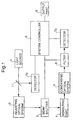
- Fig. 7 shows a structural embodiment comprising a correction optical system for correcting fluctuation of a light source intensity.
- An excitation side bandpass filter 10 is arranged between an electronic shutter 3a and a mirror 2c, and a beam splitter 11 is arranged between the excitation side bandpass filter 10 and the mirror 2c, in order to take out part of excitation light from a light source.
- the excitation light taken out by the beam splitter 11 is incident upon and detected by a detector 7b through a neutral density filter 13 for adjusting its intensity.
- the detector 7b comprises an A-D converter for converting its detection signal to a digital signal, so that the digitized detection signal is inputted in a personal computer 8 as a signal for correcting fluctuation of the excitation light intensity and the detection signal by the detector 7a is corrected.
- a light source and a detector for visible application may be employed.
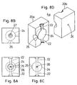
- Figs. 8A, 8B, 8C and 8D are a front elevational view, a plan view, a right side elevational view and an exploded perspective view showing an integrating sphere type scattered light reinforcing holder serving as the sample cell holder 4a in the measuring part 4 respectively.
- the sample cell holder 4a consists of two members 20a and 20b, and comprises cell holding parts 22 on both ends, an integrating sphere part 24 which is held between and connected with the cell holding parts 22, an incidence hole 25 for irradiating a cell which is held by the integrating sphere part 24 with excitation light, and an outgoing hole 26 for taking out scattered light generated from a sample in the cell to the exterior.
- excitation light incident direction and the scattered light taking out direction are at 90 degrees in the embodiment shown in Figs. 8A to 8D, these directions may alternatively be at 180 degrees, i.e., the incidence hole 25 and the outgoing hole 26 may be a common single hole.
- Figs. 9A, 9B and 9C are a front elevational view, a plan view and a perspective view showing a flow cell 4b which is suitably mounted on the cell holder 4a shown in Figs. 8A to 8D.
- a part of the flow cell 4b feeding the sample is made of quartz, and this flow cell 4b comprises a spherical part 30 which is attached to the integrating sphere part 24 of the cell holder 4a, and cylindrical inlet/outlet parts 32 which extend on both sides thereof to be attached to the cell holding parts 22.
- the inlet/outlet parts 32 are provided with flanges 34 to be fixed to the cell holder 4a.
- Figs. 10A, 10B, 11A and 11B illustrate results of Raman scattering spectra of 99 % acetone measured through conventional Raman scattering measuring apparatuses (FT-Raman spectrophotometers) comprising Fourier transform spectroscopes respectively.
- InGaAs laser diodes by SDL, U.S.A.
- Figs. 10A and 11A illustrate the case of employing no cell holder
- Figs. 10B and 11B illustrate the case of employing the integrating sphere type cell holder 4a shown in Figs. 8A to 8D respectively.
- the axes of ordinates show detected intensities, and the axes of abscissas show shift wavenumbers from excitation wavelengths.
- Figs. 10A and 10B show the results compared on the same scale of the detected intensities on the axes of ordinates
- Figs. 11A and 11B show the same results as those in Figs. 10A and 10B while increasing the gains of Fig. 11A in the range of shift wavenumbers of 0 to 2500 cm -1 to attain substantially equal peak heights. From these results, it is understood that Raman scattered light was reinforced to about 30 times by employing the integrating sphere type cell holder shown in Figs. 8A to 8D. Further, the S-N ratios were also improved as clearly understood from the comparison results of Figs. 11A and 11b.
- Figs. 12A and 12B illustrate results of Raman scattering measurement through wavelengths of excitation light.
- Samples were prepared by adding glucose into urine to be 2 M.
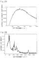
- Fig. 12A shows a spectrum measured by employing an argon ion laser beam of 514.5 nm of a visible region as excitation light through a Raman spectrophotometer having a CCD detection element as a detector.
- an influence by fluorescence was so strong that it was difficult to determine peaks of Raman scattering by glucose.
- determination of glucose by Raman scattering was difficult.
- Fig. 12B shows a spectrum measured by employing a laser beam of 1000 nm in a near infrared region by a laser diode as excitation light through an FT-Raman spectrophotometer comprising a near infrared detector.
- an influence by fluorescence was small and Raman scattering peaks clearly appeared.
- the peak appearing at 1130 cm -1 is Raman scattering based on C-O stretching vibration of glucose, and glucose can be determined through this peak.
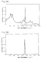
- FIG. 13A illustrates a Raman spectrum of a sample containing 2 M of glucose in urine measured by employing a laser beam of 1000 nm through an FT-Raman spectrophotometer, similarly to Fig. 12B.
- Broken lines in Fig. 13A show transmission wavelength characteristics of a holographic bandpass filter having Gaussian function type spectro-optic characteristics, which was so designed that the central wavelength of its transmission region was at a shift wavenumber of 1130 cm -1 from an excitation light wavelength, the half bandwidth was 1 nm and the transmittance was 98 %.
- Fig. 13B shows a result obtained by measuring the urogenous glucose sample through the measuring apparatus shown in Fig. 6 by employing a laser beam of 1000 nm while using a bandpass filter having the transmission wavelength characteristics shown by the broken lines in Fig. 13A. Only a peak at a shift wavenumber of 1130 cm -1 from an excitation light wavelength was detected. Quantitative measurement of glucose in a sample can be made through this peak.
- Fig. 14 shows the relations between urogenous glucose concentrations and Raman scattering peak intensities on the basis of the Raman scattering peak intensities at a shift wavenumber of 1130 cm -1 in case of employing a bandpass filter having a half bandwidth of 1 nm through the same measuring apparatus as that employed for obtaining the peak shown in Fig. 13B.
- the urogenous glucose concentrations were measured through a sugar meter (GT-1620 by Kyoto Dai-ichi Kagaku Co., Ltd.).
- the correlation coefficient R of a straight line shown in Fig. 14 was 0.980.
- Fig. 15A shows a Raman spectrum of a sample containing 2 M of glucose in urine measured by employing a laser beam of 1000 nm through an FT-Raman spectrophotometer, similarly to Fig. 12B.
- Broken lines in Fig. 15A show transmission wavelength characteristics of a holographic bandpass filter which was so designed that the central wavelength of its transmission region was at a shift wavenumber of 1130 cm -1 from an excitation light wavelength, the half bandwidth was 5 nm and the transmittance was 98 %.
- Fig. 15B shows a result obtained by measuring the urogenous glucose sample through the measuring apparatus shown in Fig. 6 by employing a laser beam of 1000 nm while using a bandpass filter having the transmission wavelength characteristics shown by the broken lines in Fig. 15A. Only a peak at a shift wavenumber of 1130 cm -1 from an excitation light wavelength was detected. Quantitative measurement of glucose in a sample can be made through this peak.
- Fig. 16 shows the relations between urogenous glucose concentrations and Raman scattering peak intensities measured on the basis of the Raman scattering peak intensities at a shift wavenumber of 1130 cm -1 in case of employing a bandpass filter having a half bandwidth of 5 nm through the same measuring apparatus as that employed for obtaining the peak shown in Fig. 15B.
- the correlation coefficient R of a straight line shown in Fig. 16 was 0.991.
- FIG. 17A illustrates a Raman spectrum of CO 2 gas measured by employing an argon ion laser beam of 514.5 nm of a visible region as excitation light through a Raman spectrophotometer having a CCD detection element as a detector.
- Broken lines in Fig. 17A show transmission wavelength characteristics of a bandpass filter which was so designed that the central wavelength of its transmission region was at a shift wavenumber of 1386 cm -1 from an excitation light wavelength and the half bandwidth was 1 nm.
- Fig. 17B shows a result of measurement of CO 2 gas through the measuring apparatus shown in Fig. 6 by employing an argon ion laser beam of 514.5 nm while using a bandpass filter having the transmission wavelength characteristics shown by the broken lines in Fig. 17A. Only a peak at a shift wavenumber of 1386 cm -1 from an excitation light wavelength was detected. Quantitative measurement of CO 2 in a sample can be made through this peak.
- FIG. 18A illustrates a Raman spectrum of CO 2 gas measured by employing an argon ion laser beam of 514.5 nm of a visible region as excitation light through a Raman spectrophotometer having a CCD detection element as a detector.
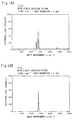
- Broken lines in Fig. 18A show transmission wavelength characteristics of a bandpass filter which was so designed that the central wavelength of its transmission region was at a shift wavenumber of 1386 cm -1 from an excitation light wavelength and the half bandwidth was 5 nm.
- Fig. 18B shows a result of measurement of CO 2 gas through the measuring apparatus of the embodiment shown in Fig. 6 by employing an argon ion laser beam of 514.5 nm while using a bandpass filter having the transmission wavelength characteristics shown by the broken lines in Fig. 18A. While scattered light around a peak at a shift wavenumber of 1386 cm -1 from an excitation light wavelength was detected, quantitative measurement of CO 2 in a sample can be made through this peak.
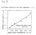
- Fig. 19 shows the relations between CO 2 in gas and Raman scattering peak intensities on the basis of the peak intensities at a shift wavenumber of 1386 cm -1 measured by the same measuring apparatus as that obtaining the peak of Fig. 18B.
- the correlation coefficient R of a straight line shown in Fig. 19 was 0.98.
Landscapes
- Health & Medical Sciences (AREA)
- Nuclear Medicine, Radiotherapy & Molecular Imaging (AREA)
- Physics & Mathematics (AREA)
- Life Sciences & Earth Sciences (AREA)
- Chemical & Material Sciences (AREA)
- Analytical Chemistry (AREA)
- Biochemistry (AREA)
- General Health & Medical Sciences (AREA)
- General Physics & Mathematics (AREA)
- Immunology (AREA)
- Pathology (AREA)
- Investigating, Analyzing Materials By Fluorescence Or Luminescence (AREA)
- Investigating Or Analysing Materials By Optical Means (AREA)
- Photometry And Measurement Of Optical Pulse Characteristics (AREA)
Applications Claiming Priority (2)
| Application Number | Priority Date | Filing Date | Title |
|---|---|---|---|
| JP35335195A JPH09184809A (ja) | 1995-12-30 | 1995-12-30 | 散乱光測定装置 |
| JP353351/95 | 1995-12-30 |
Publications (2)
| Publication Number | Publication Date |
|---|---|
| EP0781990A1 true EP0781990A1 (de) | 1997-07-02 |
| EP0781990B1 EP0781990B1 (de) | 2007-01-24 |
Family
ID=18430256
Family Applications (1)
| Application Number | Title | Priority Date | Filing Date |
|---|---|---|---|
| EP19960120962 Expired - Lifetime EP0781990B1 (de) | 1995-12-30 | 1996-12-27 | Vorrichtung zur Messung von Raman-Streulicht |
Country Status (5)
| Country | Link |
|---|---|
| US (1) | US5754289A (de) |
| EP (1) | EP0781990B1 (de) |
| JP (1) | JPH09184809A (de) |
| CN (1) | CN1075195C (de) |
| DE (1) | DE69636862T2 (de) |
Cited By (10)
| Publication number | Priority date | Publication date | Assignee | Title |
|---|---|---|---|---|
| DE19735205A1 (de) * | 1997-08-14 | 1999-02-25 | Gustav Prof Dr Techn Schweiger | Verfahren zur spektroskopischen Rußmessung |
| WO1999012019A1 (en) * | 1997-09-01 | 1999-03-11 | Akzo Nobel N.V. | Technique for measuring properties of polymeric fibres |
| US6087182A (en) * | 1998-08-27 | 2000-07-11 | Abbott Laboratories | Reagentless analysis of biological samples |
| DE10146826A1 (de) * | 2001-09-19 | 2003-04-10 | Deutsch Zentr Luft & Raumfahrt | Analyseverfahren für Silizium-Germanium-Legierungen und Vorrichtung zur Herstellung von Halbleiterschichtstrukturen mit Silizium-Germanium-Legierungsschichten |
| EP1459053A1 (de) * | 2001-12-21 | 2004-09-22 | CME Telemetrix Inc. | Raman-spektroskopisches system mit einem integrationshohlraum |
| US7911604B2 (en) | 2005-11-25 | 2011-03-22 | The Science And Technology Facilities Council | Security screening using raman analysis |
| CN101995387A (zh) * | 2010-09-14 | 2011-03-30 | 杭州电子科技大学 | 一种多功能紫外-可见光谱仪 |
| EP3256840B1 (de) * | 2015-02-10 | 2023-08-09 | University Court of The University of St Andrews | Systeme und methoden welche einen integrierten sphären-lichtkollektor verwenden |
| WO2024178209A1 (en) * | 2023-02-24 | 2024-08-29 | Thermo Scientific Portable Analytical Instruments Inc. | Sample clamp for a spectroscopic instrument |
| US12203848B2 (en) | 2020-01-31 | 2025-01-21 | ODx Innovations Limited | Apparatus, system and method for measuring properties of a sample |
Families Citing this family (56)
| Publication number | Priority date | Publication date | Assignee | Title |
|---|---|---|---|---|
| JP3774001B2 (ja) * | 1995-10-18 | 2006-05-10 | アークレイ株式会社 | 尿中成分測定装置 |
| US6124928A (en) * | 1997-03-07 | 2000-09-26 | Kaiser Optical Systems, Inc. | Methods and apparatus for obtaining a selectively polarized induced emission |
| GB9715550D0 (en) * | 1997-07-24 | 1997-10-01 | Ciba Geigy Ag | Plastics compostions |
| JP4537503B2 (ja) * | 1998-01-14 | 2010-09-01 | ローム アンド ハース ケミカルズ エル エル シー | レトルト・パウチのために有用なウレタン・ラミネーティング接着剤 |
| US6064897A (en) * | 1998-06-01 | 2000-05-16 | Abbott Laboratories | Sensor utilizing Raman spectroscopy for non-invasive monitoring of analytes in biological fluid and method of use |
| US6373567B1 (en) | 1999-12-17 | 2002-04-16 | Micron Optical Systems | Dispersive near-IR Raman spectrometer |
| US6751576B2 (en) | 2000-03-10 | 2004-06-15 | Cognis Corporation | On-site agricultural product analysis system and method of analyzing |
| JP2002005835A (ja) * | 2000-06-23 | 2002-01-09 | 宏夫 ▲浜▼口 | ラマン分光測定装置及びそれを用いた生体試料分析方法 |
| US6522903B1 (en) * | 2000-10-19 | 2003-02-18 | Medoptix, Inc. | Glucose measurement utilizing non-invasive assessment methods |
| US7194369B2 (en) * | 2001-07-23 | 2007-03-20 | Cognis Corporation | On-site analysis system with central processor and method of analyzing |
| US7359116B2 (en) | 2001-10-16 | 2008-04-15 | Hamilton Thome Biosciences, Inc. | Microscope turret mounted laser EPI-illumination port |
| US9335532B2 (en) * | 2001-10-16 | 2016-05-10 | Hamilton Thorne, Inc. | Laser assembly for use with a microscope |
| GB0216934D0 (en) * | 2002-07-20 | 2002-08-28 | Council Cent Lab Res Councils | Optical apparatus |
| TW564513B (en) * | 2002-10-21 | 2003-12-01 | Au Optronics Corp | Testing apparatus for polysilicon thin film crystal quality, test and control method thereof |
| US20040225206A1 (en) * | 2003-05-09 | 2004-11-11 | Kouchnir Mikhail A. | Non-invasive analyte measurement device having increased signal to noise ratios |
| US20050043597A1 (en) * | 2003-07-31 | 2005-02-24 | Skymoon Research And Development, Llc | Optical vivo probe of analyte concentration within the sterile matrix under the human nail |
| JP2005121479A (ja) * | 2003-10-16 | 2005-05-12 | Tokyo Instruments Inc | 共焦点顕微分光装置 |
| JP2007509319A (ja) * | 2003-10-17 | 2007-04-12 | アクサン・テクノロジーズ・インコーポレーテッド | 多チャネルラマン分光システムおよび方法 |
| JP2005140558A (ja) * | 2003-11-04 | 2005-06-02 | Oyo Kogaku Kenkyusho | ガス検出器 |
| US20050137469A1 (en) * | 2003-12-17 | 2005-06-23 | Berman Herbert L. | Single detector infrared ATR glucose measurement system |
| US20050171413A1 (en) * | 2004-02-04 | 2005-08-04 | Medoptix, Inc. | Integrated device for non-invasive analyte measurement |
| US20050187438A1 (en) * | 2004-02-24 | 2005-08-25 | Skymoon Research & Development, Llc | Anti-stokes raman in vivo probe of analyte concentrations through the human nail |
| US7019311B1 (en) * | 2004-03-25 | 2006-03-28 | Sandia Corporation | Laser-based irradiation apparatus and methods for monitoring the dose-rate response of semiconductor devices |
| US20060063991A1 (en) * | 2004-08-09 | 2006-03-23 | Dejin Yu | Method and apparatus for non-invasive measurement of blood analytes with dynamic spectral calibration |
| US20060063992A1 (en) * | 2004-08-09 | 2006-03-23 | Dejin Yu | Method and apparatus for non-invasive measurement of blood analytes |
| US20060063993A1 (en) * | 2004-08-09 | 2006-03-23 | Dejin Yu | Method and apparatus for non-invasive measurement of blood analytes |
| US20060211926A1 (en) * | 2005-03-21 | 2006-09-21 | Dejin Yu | Non-invasive Raman measurement apparatus with broadband spectral correction |
| US8180422B2 (en) * | 2005-04-15 | 2012-05-15 | Bayer Healthcare Llc | Non-invasive system and method for measuring an analyte in the body |
| WO2006116637A2 (en) * | 2005-04-27 | 2006-11-02 | Massachusetts Institute Of Technology | Raman spectroscopy for non-invasive glucose measurements |
| JP4637643B2 (ja) * | 2005-05-18 | 2011-02-23 | 日本分光株式会社 | 分光分析装置 |
| WO2006127766A1 (en) * | 2005-05-25 | 2006-11-30 | Bayer Healthcare Llc | Methods of using raman spectral information in determining analyte concentrations |
| US9103793B2 (en) * | 2005-07-22 | 2015-08-11 | Massachusetts Institute Of Technology | Intrinsic Raman spectroscopy |
| CN100567963C (zh) * | 2006-04-19 | 2009-12-09 | 中国科学院半导体研究所 | 显微拉曼谱仪与近红外光谱仪的联合测试系统 |
| CA2664133C (en) * | 2006-08-22 | 2012-10-23 | Bayer Healthcare Llc | A method for correcting a spectral image for optical aberrations using software |
| US7603151B2 (en) * | 2006-08-22 | 2009-10-13 | Bayer Healthcare Llc | Non-invasive methods of using spectral information in determining analyte concentrations |
| US8077309B2 (en) | 2007-01-29 | 2011-12-13 | Applied Instrument Technologies, Inc. | Chemical analyzer for industrial process control |
| JP2009014510A (ja) * | 2007-07-04 | 2009-01-22 | Hitachi High-Technologies Corp | 検査方法及び検査装置 |
| US8149504B2 (en) * | 2008-06-10 | 2012-04-03 | Hamilton Thorne Biosciences, Inc. | Optical indicator for microscopic laser beam manipulation |
| CA2742847A1 (en) * | 2008-11-07 | 2010-05-14 | Diarmaid H. Douglas-Hamilton | Modular objective assembly |
| FR2940447B1 (fr) * | 2008-12-23 | 2011-10-21 | Continental Automotive France | Spectrometre miniature embarque dans un vehicule automobile a detecteur de mesure et detecteur de reference unique |
| JP2010210331A (ja) * | 2009-03-09 | 2010-09-24 | Fuji Electric Holdings Co Ltd | 結晶分析方法、結晶分析装置、及びプログラム |
| US9662047B2 (en) * | 2010-08-05 | 2017-05-30 | Massachusetts Institute Of Technology | Portable raman diagnostic system |
| JP5667809B2 (ja) * | 2010-08-06 | 2015-02-12 | 株式会社四国総合研究所 | 光学式ガスセンサ |
| JP2012122797A (ja) * | 2010-12-07 | 2012-06-28 | Sony Corp | 酸化物半導体電極の評価方法、酸化物半導体電極の評価装置および酸化物半導体電極の製造装置 |
| JP5645676B2 (ja) * | 2011-01-07 | 2014-12-24 | 三菱重工業株式会社 | ガスの温度及び成分濃度計測装置 |
| US8879060B2 (en) | 2013-04-02 | 2014-11-04 | Hong Kong Applied Science and Technology Research Institute Company Limited | Raman signal detection and analysing system and a method thereof |
| GB201503911D0 (en) * | 2015-03-09 | 2015-04-22 | Renishaw Plc | Transmission raman spectroscopy |
| WO2018129435A1 (en) | 2017-01-09 | 2018-07-12 | Mks Technology, Inc. | Method of measuring raman scattering and related spectrometers and laser sources |
| US10151633B2 (en) | 2017-02-09 | 2018-12-11 | Savannah River Nuclear Solutions, Llc | High accuracy absorbance spectrophotometers |
| JP6946688B2 (ja) * | 2017-03-23 | 2021-10-06 | 株式会社豊田中央研究所 | 光通過回数調整装置、光通過回数調整方法、及び濃度算出装置 |
| US20210169335A1 (en) * | 2017-11-30 | 2021-06-10 | Shinsei Co., Ltd. | Health condition management system, method for controlling health condition management system, and program |
| US10656012B2 (en) * | 2017-12-22 | 2020-05-19 | Massachusetts Institute Of Technology | Swept-source Raman spectroscopy systems and methods |
| JP7035736B2 (ja) * | 2018-04-03 | 2022-03-15 | 株式会社豊田中央研究所 | 濃度測定装置及び濃度測定方法 |
| CN108426872A (zh) * | 2018-06-13 | 2018-08-21 | 武汉理工大学 | 一种用于拉曼散射光纤传感的气体浓度在线测量系统及其方法 |
| CN114460061A (zh) * | 2022-04-08 | 2022-05-10 | 广东大湾区空天信息研究院 | 一种时间门控拉曼光谱系统及拉曼光谱校正方法 |
| KR102590718B1 (ko) * | 2023-05-30 | 2023-10-19 | 주식회사 아폴론 | 라만 신호 기반 연속 혈당 측정 장치 |
Citations (8)
| Publication number | Priority date | Publication date | Assignee | Title |
|---|---|---|---|---|
| US4648714A (en) * | 1985-09-11 | 1987-03-10 | University Of Utah | Molecular gas analysis by Raman scattering in intracavity laser configuration |
| GB2228316A (en) * | 1989-01-19 | 1990-08-22 | De Beers Ind Diamond | Determining the background radiation level in the region of a characteristic Raman peak |
| US4953976A (en) * | 1989-03-20 | 1990-09-04 | Spectral Sciences, Inc. | Gas species monitor system |
| WO1991011703A1 (en) * | 1990-02-02 | 1991-08-08 | Thomas De La Rue And Company Limited | Detection apparatus |
| JPH0526728A (ja) | 1991-07-24 | 1993-02-02 | Jasco Corp | ラマン分光用分光器 |
| JPH063271A (ja) | 1992-06-22 | 1994-01-11 | Fujitsu Ltd | 分光分析装置 |
| US5373358A (en) * | 1991-08-23 | 1994-12-13 | Fuji Xerox Co., Ltd. | Excitation wavelength sweeping type raman spectroscopic apparatus |
| JPH0785057A (ja) | 1993-06-26 | 1995-03-31 | Just Syst Corp | 構文解析方法及び装置 |
Family Cites Families (6)
| Publication number | Priority date | Publication date | Assignee | Title |
|---|---|---|---|---|
| GB222836A (de) * | 1923-10-01 | 1925-04-23 | Albert Fritz Meyerhofer | |
| DE2935812A1 (de) * | 1979-09-05 | 1981-03-12 | Fa. Carl Zeiss, 7920 Heidenheim | Verfahren zur werkstoffpruefung |
| GB8706421D0 (en) * | 1987-03-18 | 1987-04-23 | British Petroleum Co Plc | Detection method |
| US5386295A (en) * | 1990-10-01 | 1995-01-31 | Eastman Kodak Company | Postacquired spectrophotometers |
| JPH0785057B2 (ja) * | 1992-03-05 | 1995-09-13 | 紀本電子工業株式会社 | 微量成分の分析用ラマン分光計 |
| JPH0749309A (ja) * | 1993-08-05 | 1995-02-21 | Kyoto Daiichi Kagaku:Kk | 光散乱式成分濃度測定装置および方法 |
-
1995
- 1995-12-30 JP JP35335195A patent/JPH09184809A/ja active Pending
-
1996
- 1996-12-27 EP EP19960120962 patent/EP0781990B1/de not_active Expired - Lifetime
- 1996-12-27 DE DE1996636862 patent/DE69636862T2/de not_active Expired - Lifetime
- 1996-12-27 US US08/777,282 patent/US5754289A/en not_active Expired - Lifetime
- 1996-12-30 CN CN96123836A patent/CN1075195C/zh not_active Expired - Fee Related
Patent Citations (8)
| Publication number | Priority date | Publication date | Assignee | Title |
|---|---|---|---|---|
| US4648714A (en) * | 1985-09-11 | 1987-03-10 | University Of Utah | Molecular gas analysis by Raman scattering in intracavity laser configuration |
| GB2228316A (en) * | 1989-01-19 | 1990-08-22 | De Beers Ind Diamond | Determining the background radiation level in the region of a characteristic Raman peak |
| US4953976A (en) * | 1989-03-20 | 1990-09-04 | Spectral Sciences, Inc. | Gas species monitor system |
| WO1991011703A1 (en) * | 1990-02-02 | 1991-08-08 | Thomas De La Rue And Company Limited | Detection apparatus |
| JPH0526728A (ja) | 1991-07-24 | 1993-02-02 | Jasco Corp | ラマン分光用分光器 |
| US5373358A (en) * | 1991-08-23 | 1994-12-13 | Fuji Xerox Co., Ltd. | Excitation wavelength sweeping type raman spectroscopic apparatus |
| JPH063271A (ja) | 1992-06-22 | 1994-01-11 | Fujitsu Ltd | 分光分析装置 |
| JPH0785057A (ja) | 1993-06-26 | 1995-03-31 | Just Syst Corp | 構文解析方法及び装置 |
Non-Patent Citations (2)
| Title |
|---|
| D.A. CARTER ET AL.: "FREQUENCY/WAVELENGTH CALIBRATION OF MULTIPURPOSE MULTICHANNEL RAMAN SPECTROMETERS. PART I: INSTRUMENTAL FACTORS AFFECTING PRECISION", APPLIED SPECTROSCOPY, vol. 49, no. 11, November 1995 (1995-11-01), BALTIMORE US, pages 1550 - 1560, XP000537243 * |
| J.M. WILLIAMSON ET AL.: "NEAR-INFRARED RAMAN SPECTROSCOPY WITH A 783-NM DIODE LASER AND CCD ARRAY DETECTOR", APPLIED SPECTROSCOPY, vol. 43, no. 1, January 1989 (1989-01-01), BALTIMORE US, pages 372 - 375, XP000125907 * |
Cited By (19)
| Publication number | Priority date | Publication date | Assignee | Title |
|---|---|---|---|---|
| DE19735205A1 (de) * | 1997-08-14 | 1999-02-25 | Gustav Prof Dr Techn Schweiger | Verfahren zur spektroskopischen Rußmessung |
| US6423262B1 (en) | 1997-09-01 | 2002-07-23 | Akzo Nobel N.V. | Technique for measuring properties of polymeric fibres |
| WO1999012019A1 (en) * | 1997-09-01 | 1999-03-11 | Akzo Nobel N.V. | Technique for measuring properties of polymeric fibres |
| US6773922B2 (en) | 1998-08-27 | 2004-08-10 | Abbott Laboratories | Reagentless analysis of biological samples |
| US6087182A (en) * | 1998-08-27 | 2000-07-11 | Abbott Laboratories | Reagentless analysis of biological samples |
| US6426045B1 (en) | 1998-08-27 | 2002-07-30 | Abbott Laboratories | Reagentless analysis of biological samples |
| US6365109B1 (en) | 1998-08-27 | 2002-04-02 | Abbott Laboratories | Reagentless analysis of biological samples |
| DE10146826B4 (de) * | 2001-09-19 | 2004-11-25 | Deutsches Zentrum für Luft- und Raumfahrt e.V. | Verfahren zur Analyse von Silizium-Germanium-Legierungen und Vorrichtung zur Herstellung von Halbleiterschichtstrukturen mit Silizium-Germanium-Legierungsschichten |
| US6744501B2 (en) | 2001-09-19 | 2004-06-01 | Deutsches Zentrum Fuer Luft-Und Raumfahrt E.V. | Method of analyzing silicon-germanium alloys and apparatus for manufacturing semiconductor layer structures with silicon-germanium alloy layers |
| DE10146826A1 (de) * | 2001-09-19 | 2003-04-10 | Deutsch Zentr Luft & Raumfahrt | Analyseverfahren für Silizium-Germanium-Legierungen und Vorrichtung zur Herstellung von Halbleiterschichtstrukturen mit Silizium-Germanium-Legierungsschichten |
| EP1459053A1 (de) * | 2001-12-21 | 2004-09-22 | CME Telemetrix Inc. | Raman-spektroskopisches system mit einem integrationshohlraum |
| US7911604B2 (en) | 2005-11-25 | 2011-03-22 | The Science And Technology Facilities Council | Security screening using raman analysis |
| US8085396B2 (en) | 2006-04-05 | 2011-12-27 | The Science And Technology Facilities Council | Raman analysis |
| US8259902B2 (en) | 2006-04-05 | 2012-09-04 | The Science And Technology Facilities Council | Raman analysis of tissue and/or calcifications |
| CN101995387A (zh) * | 2010-09-14 | 2011-03-30 | 杭州电子科技大学 | 一种多功能紫外-可见光谱仪 |
| CN101995387B (zh) * | 2010-09-14 | 2012-05-23 | 杭州电子科技大学 | 一种多功能紫外-可见光谱仪 |
| EP3256840B1 (de) * | 2015-02-10 | 2023-08-09 | University Court of The University of St Andrews | Systeme und methoden welche einen integrierten sphären-lichtkollektor verwenden |
| US12203848B2 (en) | 2020-01-31 | 2025-01-21 | ODx Innovations Limited | Apparatus, system and method for measuring properties of a sample |
| WO2024178209A1 (en) * | 2023-02-24 | 2024-08-29 | Thermo Scientific Portable Analytical Instruments Inc. | Sample clamp for a spectroscopic instrument |
Also Published As
| Publication number | Publication date |
|---|---|
| DE69636862T2 (de) | 2007-06-06 |
| DE69636862D1 (de) | 2007-03-15 |
| JPH09184809A (ja) | 1997-07-15 |
| CN1157915A (zh) | 1997-08-27 |
| US5754289A (en) | 1998-05-19 |
| EP0781990B1 (de) | 2007-01-24 |
| CN1075195C (zh) | 2001-11-21 |
Similar Documents
| Publication | Publication Date | Title |
|---|---|---|
| US5754289A (en) | Raman scattered light measuring apparatus | |
| US5828450A (en) | Spectral measuring apparatus and automatic analyzer | |
| EP0764844B1 (de) | Verfahren zur Analyse mittels Lichtstreuung | |
| EP1784624B1 (de) | Kalibrierung für spektroskopische analysen | |
| EP1784625B1 (de) | Autonome kalibrierung für optische analysesysteme | |
| EP0760938B1 (de) | Gerät und verfahren zur raman-spektrometrie | |
| EP0751382B1 (de) | Verfahren und Vorrichtung zum Messen von Spektren | |
| US6141095A (en) | Apparatus for measuring and applying instrumentation correction to produce a standard Raman spectrum | |
| US7414717B2 (en) | System and method for detection and identification of optical spectra | |
| WO2007061436A1 (en) | Self calibration methods for optical analysis system | |
| US7292342B2 (en) | Entangled photon fourier transform spectroscopy | |
| CN103649726A (zh) | 用于荧光和吸收率分析的系统和方法 | |
| EP0801301A2 (de) | Optisches Messverfahren für Mevalonsäure | |
| JPH0989775A (ja) | 分光測定装置及び自動分析装置 | |
| US20180266884A1 (en) | Multichannel ultra-sensitive optical spectroscopic detection | |
| JPH06317471A (ja) | ポリクロメータシステム及び分光分析方法 | |
| JP7356498B2 (ja) | プラズマスペクトル分析を介してサンプルの材料組成を分析するための装置 | |
| EP1203219B1 (de) | Vorrichtung zur messung und anwendung der instrumentenkorrektur zur erzeugung eines standard-ramanspektrums | |
| JPH09145619A (ja) | 散乱光等の分光測定方法及び装置 | |
| US20250321191A1 (en) | Analysis apparatus | |
| US4171912A (en) | Element analyzer exploiting a magneto-optic effect | |
| MXPA96005847A (en) | Raman and met spectrometry apparatus |
Legal Events
| Date | Code | Title | Description |
|---|---|---|---|
| PUAI | Public reference made under article 153(3) epc to a published international application that has entered the european phase |
Free format text: ORIGINAL CODE: 0009012 |
|
| AK | Designated contracting states |
Kind code of ref document: A1 Designated state(s): DE FR GB IT |
|
| 17P | Request for examination filed |
Effective date: 19971016 |
|
| 17Q | First examination report despatched |
Effective date: 20030612 |
|
| GRAP | Despatch of communication of intention to grant a patent |
Free format text: ORIGINAL CODE: EPIDOSNIGR1 |
|
| RIC1 | Information provided on ipc code assigned before grant |
Ipc: G01J 3/44 20060101ALI20060629BHEP Ipc: G01N 21/65 20060101AFI20060629BHEP |
|
| RTI1 | Title (correction) |
Free format text: RAMAN SCATTERED LIGHT MEASURING APPARATUS |
|
| GRAS | Grant fee paid |
Free format text: ORIGINAL CODE: EPIDOSNIGR3 |
|
| RAP1 | Party data changed (applicant data changed or rights of an application transferred) |
Owner name: ARKRAY, INC |
|
| GRAA | (expected) grant |
Free format text: ORIGINAL CODE: 0009210 |
|
| AK | Designated contracting states |
Kind code of ref document: B1 Designated state(s): DE FR GB IT |
|
| REG | Reference to a national code |
Ref country code: GB Ref legal event code: FG4D |
|
| REF | Corresponds to: |
Ref document number: 69636862 Country of ref document: DE Date of ref document: 20070315 Kind code of ref document: P |
|
| ET | Fr: translation filed | ||
| PLBE | No opposition filed within time limit |
Free format text: ORIGINAL CODE: 0009261 |
|
| STAA | Information on the status of an ep patent application or granted ep patent |
Free format text: STATUS: NO OPPOSITION FILED WITHIN TIME LIMIT |
|
| 26N | No opposition filed |
Effective date: 20071025 |
|
| PGFP | Annual fee paid to national office [announced via postgrant information from national office to epo] |
Ref country code: GB Payment date: 20141219 Year of fee payment: 19 Ref country code: DE Payment date: 20141211 Year of fee payment: 19 |
|
| PGFP | Annual fee paid to national office [announced via postgrant information from national office to epo] |
Ref country code: FR Payment date: 20141219 Year of fee payment: 19 |
|
| PGFP | Annual fee paid to national office [announced via postgrant information from national office to epo] |
Ref country code: IT Payment date: 20141223 Year of fee payment: 19 |
|
| REG | Reference to a national code |
Ref country code: DE Ref legal event code: R119 Ref document number: 69636862 Country of ref document: DE |
|
| GBPC | Gb: european patent ceased through non-payment of renewal fee |
Effective date: 20151227 |
|
| REG | Reference to a national code |
Ref country code: FR Ref legal event code: ST Effective date: 20160831 |
|
| PG25 | Lapsed in a contracting state [announced via postgrant information from national office to epo] |
Ref country code: GB Free format text: LAPSE BECAUSE OF NON-PAYMENT OF DUE FEES Effective date: 20151227 Ref country code: DE Free format text: LAPSE BECAUSE OF NON-PAYMENT OF DUE FEES Effective date: 20160701 |
|
| PG25 | Lapsed in a contracting state [announced via postgrant information from national office to epo] |
Ref country code: FR Free format text: LAPSE BECAUSE OF NON-PAYMENT OF DUE FEES Effective date: 20151231 |
|
| PG25 | Lapsed in a contracting state [announced via postgrant information from national office to epo] |
Ref country code: IT Free format text: LAPSE BECAUSE OF NON-PAYMENT OF DUE FEES Effective date: 20151227 |