EP0782327B1 - Procédé de modification de la résolution d'une image numérisée - Google Patents
Procédé de modification de la résolution d'une image numérisée Download PDFInfo
- Publication number
- EP0782327B1 EP0782327B1 EP96402648A EP96402648A EP0782327B1 EP 0782327 B1 EP0782327 B1 EP 0782327B1 EP 96402648 A EP96402648 A EP 96402648A EP 96402648 A EP96402648 A EP 96402648A EP 0782327 B1 EP0782327 B1 EP 0782327B1
- Authority
- EP
- European Patent Office
- Prior art keywords
- pixels
- image
- intensities
- intensity
- resolution
- Prior art date
- Legal status (The legal status is an assumption and is not a legal conclusion. Google has not performed a legal analysis and makes no representation as to the accuracy of the status listed.)
- Expired - Lifetime
Links
- 238000000034 method Methods 0.000 title claims abstract description 19
- 239000011159 matrix material Substances 0.000 claims abstract description 17
- 230000007704 transition Effects 0.000 claims abstract description 8
- 230000008569 process Effects 0.000 abstract description 5
- 238000011835 investigation Methods 0.000 abstract 1
- 238000002955 isolation Methods 0.000 abstract 1
- 238000012986 modification Methods 0.000 abstract 1
- 230000004048 modification Effects 0.000 abstract 1
- 238000004458 analytical method Methods 0.000 description 8
- 238000009499 grossing Methods 0.000 description 8
- 230000003287 optical effect Effects 0.000 description 7
- 238000004364 calculation method Methods 0.000 description 4
- 230000036961 partial effect Effects 0.000 description 3
- 238000011002 quantification Methods 0.000 description 3
- 238000013139 quantization Methods 0.000 description 3
- 230000002829 reductive effect Effects 0.000 description 3
- 230000005540 biological transmission Effects 0.000 description 2
- 230000015556 catabolic process Effects 0.000 description 2
- 230000008859 change Effects 0.000 description 2
- 238000006731 degradation reaction Methods 0.000 description 2
- 230000008901 benefit Effects 0.000 description 1
- 239000003086 colorant Substances 0.000 description 1
- 239000002131 composite material Substances 0.000 description 1
- 230000001186 cumulative effect Effects 0.000 description 1
- 238000010586 diagram Methods 0.000 description 1
- 230000007717 exclusion Effects 0.000 description 1
- 238000000605 extraction Methods 0.000 description 1
- 238000001914 filtration Methods 0.000 description 1
- 230000003993 interaction Effects 0.000 description 1
- 230000000670 limiting effect Effects 0.000 description 1
- 239000000463 material Substances 0.000 description 1
- 230000005012 migration Effects 0.000 description 1
- 238000013508 migration Methods 0.000 description 1
- 239000000203 mixture Substances 0.000 description 1
- 230000000717 retained effect Effects 0.000 description 1
- 230000002441 reversible effect Effects 0.000 description 1
- 238000005070 sampling Methods 0.000 description 1
- 238000005204 segregation Methods 0.000 description 1
- 230000035945 sensitivity Effects 0.000 description 1
- 230000009466 transformation Effects 0.000 description 1
- 239000013598 vector Substances 0.000 description 1
Images

Classifications
-
- H—ELECTRICITY
- H04—ELECTRIC COMMUNICATION TECHNIQUE
- H04N—PICTORIAL COMMUNICATION, e.g. TELEVISION
- H04N1/00—Scanning, transmission or reproduction of documents or the like, e.g. facsimile transmission; Details thereof
- H04N1/40—Picture signal circuits
- H04N1/409—Edge or detail enhancement; Noise or error suppression
- H04N1/4092—Edge or detail enhancement
-
- H—ELECTRICITY
- H04—ELECTRIC COMMUNICATION TECHNIQUE
- H04N—PICTORIAL COMMUNICATION, e.g. TELEVISION
- H04N1/00—Scanning, transmission or reproduction of documents or the like, e.g. facsimile transmission; Details thereof
- H04N1/40—Picture signal circuits
- H04N1/40068—Modification of image resolution, i.e. determining the values of picture elements at new relative positions
Definitions
- the invention relates to a method for modifying the resolution of an image. digitized.
- the digitization of the images makes it possible to transmit and memorize them without risk of degradation. It finds particular application in fax machines.
- the image of a document to be transmitted is scanned point by point (or element by element) by a read head of a scanner with which, at each point position, or pixel, we assign a numerical value representing. the intensity of the shade of gray read on the document. For a restitution in black and white, the shade value is compared to an average gray threshold for provide a bit 0 or 1 representing white or black.
- a printer renders the pixels, black or white, with numbers of dots per millimeter, horizontally and vertically, identical to those of the analysis head, for example 8 points / mm horizontally and 7.7 points / mm vertically.
- the plaintiff then sought to fully exploit the resolution of the printer by a change in the resolution of the received image which frees itself from the report of the initial and final resolutions, horizontally and vertically, while limiting the distortion introduced by this operation.
- JP-A 2185456 we know a process for changing the resolution of an image obtained by scanning a real image, the scanned image consisting of a plurality of pixels of determined intensity, in which one searches and isolates contours in the scanned image.
- the image obtained by this process retains the grain related to the resolution of the original scanned image.
- the present invention proposes to overcome this drawback.
- the invention relates to a method of the type defined above, characterized by the fact that additional pixels are created by interpolation original pixel intensities, taking into account only the pixels located on the same side of a contour to form a modified resolution image.
- the report of image resolutions is dispensed with.
- the image can be a black and white or color image, with or without intermediate levels of pixel intensity.
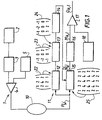
- the analysis chain 1, or scanner, of FIG. 1 belongs to a fax machine and comprises, in the order of propagation of the image signals, a sensor photosensitive 2, here CCD, an analog / digital converter 3 and a comparator 4 ensuring the comparison of the sampled intensity level of the pixels of the image of a document analyzed by CCD 2 with a threshold value intensity, representing an average intensity, stored in a register 5.
- a threshold value intensity representing an average intensity
- Comparator 4 is connected output to the PSTN 10 switched telephone network.
- the image reproduction chain 11 of another fax machine includes, input, connected to RTC 10, to its control output from a laser printer, not shown, a circuit 15 for estimating the original image, a circuit interpolation 16 and a comparator 17, receiving a threshold value medium gray intensity, stored in a register 18.
- the RTC 10 supplies also in fax data Pij a chain of contour extraction consisting of a smoothing circuit 12, a gradient calculation circuit 13 and a threshold comparator circuit 14 controlling circuit 15.
- the circuits 12-16 are specifically intended for the implementation of the method of the invention, in order to control the laser printer according to a resolution of 600 dots per inch in this example, or about 24 dots per millimeter, from the signals generated by the CCD 2 with a resolution of 8 points / mm in horizontal and 7.7 points / mm in vertical.
- the three circuits 12-14 are used to draw up a map of. contours for then. order processing of the digitized image in circuits 15-16.
- the circuits 12-14 respectively smooth the pixel intensities of the original scanned image, a calculation of the intensity gradient between pixels neighbors with smoothed intensities and a comparison of the gradients at a threshold, for provide an image or outline map.
- the scanned image which is then processed can be considered to have three "dimensions": horizontal, vertical and pixel intensity level of a sampling matrix.
- Each of these three dimensions has a quantification, respectively linked to the pitch analysis, horizontal and vertical, and to digitize the intensities in values discrete, here limited to two values, white or black. So it's about eliminating the three quantifications above, in order to reconstruct, in the form electronic, the original optical image, by a reverse transformation from that performed in the analysis chain 1.
- the receiving fax machine can thus be the equivalent of a photocopier.
- circuit 12 Associated with circuit 12 is represented a matrix 22 for weighting the pixel intensities in a limited area of the original scanned image, here 3 x 3 pixels, while at circuit 13 are associated two matrices 23, 24 of gradient calculation respectively in the horizontal direction, or line, and the vertical direction.
- the matrix 22 is centered, here successively, on each pixel of the image original digitized to calculate a composite gray intensity value taking into account the intensity, black or white, of the pixel considered and those of surrounding pixels, with an inverse function weighting law of the distance between the central pixel and each of the other pixels.
- inverse function we mean a function whose direction of variation is different from that of variable, regardless of the sensitivity of the function to variations in variable.
- the weighted average thus obtained represents, for the pixel considered, a level or density per unit of average gray area of the zone considered from the original optical image, without however erasing the "relief" of gray since the pixels. more distant have only a reduced influence. We obtain thus an estimate of the original optical image, which has practically disappeared, by smoothing, the quantization of intensity due to the black / white coding.
- the circuit 13 calculates the gradient of the gray intensities in two directions, here perpendicular.
- the weighting matrix 23 which presents an anti-symmetry with respect to its vertical axis
- three consecutive pixels of a same line provide a partial result of weighting their intensities smoothed which is positive if the pixel on the right has a smoothed intensity greater than that of the left pixel, partial result which otherwise is negative otherwise.
- the three partial results of the three lines provide by cumulative number with sign representing the intensity gradient Gh in the horizontal direction.
- the second line comprising the central pixel considered, has a weighting greater than that of the two other.
- the Gv gradient in the vertical direction is determined according to the same principle, by means of the matrix 24, which corresponds to the matrix 23 quarter turn tour. Matrices 22 and 23 thus have an allure two-dimensional Gaussian.
- a quadratic composition of the two gradients Gh and Gv provides the gradient maximum G, the direction of which can be defined as the line if necessary greater slope in a plane tangent to the "relief" of the smoothed intensities, plane defined by two vectors represented by Gh and Gv.
- the image of the intensities having thus been replaced by an image of the gradients of these, comparing the latter to a gradient threshold in the circuit 14 makes it possible to locate, for close pixels, the intensity transitions representative of a gradient exceeding the threshold and to draw up a map of contours.
- the contours could be determined otherwise, for example by using the Laplacian.
- Intensity transitions above the threshold represent limits between details of the original image with markedly different gray levels, while low amplitude gray transitions within the same detail is not detected.
- the threshold is set at a relatively high threshold S1, while, in the opposite case, where it is a photo-like image; the threshold takes a lower S2 value.
- circuits 15-16 the image processing mentioned above for the second phase.
- the weighting of the pixel intensities of the original image surrounding the central pixel is an inverse function of their distances to this pixel central, intensity to be balanced.
- Smoothing wears successively on all the pixels of the original scanned image but is mainly of interest in image areas with transitions important, that is to say along the contours.
- transmission of binary signals, black or white in which the comparator 4 is likely to switch very often when the image optic has a gray close to the threshold, and thereby create a noise of significant quantification in initially homogeneous areas, the above smoothing has the advantage of eliminating this noise and restoring homogeneity noisy areas, out of contours.
- the coefficients of the matrix 25 separated from the pixel central considered are reduced and even, in this example, go to 0.
- Figure 2 illustrates the principle of interpolation.
- each pixel of a rectangular block or mesh of the original image has respective smoothed intensities ⁇ i, j, ⁇ i + 1, j, ⁇ i, j + 1 and ⁇ i + 1, j + 1.
- the position of each pixel is identified by the theoretical center of the pixel in the original pixel matrix. For convenience, the pixels are identified by their smoothed intensity.
- the pixel Mk, l being surrounded by the other four pixels like ⁇ i, j, we apply to the intensity of each of these a weighting varying linearly from 0 to 1 depending on whether the pixel Mk, l is distant or close to the pixel like ⁇ i, j considered, horizontally or vertically (rk, rl).
- Mk, l [[rk x Or + 1, j + (1 - rk) Or , j] x (1 - rl) + [rk x NOT i + 1, j + 1 + (1 - rk) Or , j + 1] x rl] / 2
- comparator 17 then supplies a quantized signal Qk, I of printer control.
- Spatial filtering encompassing a larger area than the above mesh and taking into account sequences of aligned points passing through the point Mk, I concerned may also be considered.
Landscapes
- Engineering & Computer Science (AREA)
- Multimedia (AREA)
- Signal Processing (AREA)
- Image Processing (AREA)
- Studio Circuits (AREA)
- Facsimile Heads (AREA)
- Editing Of Facsimile Originals (AREA)
- Analysing Materials By The Use Of Radiation (AREA)
- Apparatus For Radiation Diagnosis (AREA)
- Facsimile Image Signal Circuits (AREA)
- Non-Silver Salt Photosensitive Materials And Non-Silver Salt Photography (AREA)
- Manufacture Or Reproduction Of Printing Formes (AREA)
- Polymerisation Methods In General (AREA)
- Image Analysis (AREA)
- Silver Salt Photography Or Processing Solution Therefor (AREA)
Description
- la figure 1 est un synoptique représentant une chaíne classique d'analyse de document dans un télécopieur et une chaíné de restitution d'image, mettant en oeuvre le procédé de l'invention, et
- la figure 2 illustre l'interpolation entre pixels.
- on recherche et isole des contours dans l'image numérisée et
- on crée des pixels supplémentaires par interpolation des intensités de pixels d'origine situés d'un même côté d'un contour pour former une image de résolution modifiée.
Claims (6)
- Procédé de modification de la résolution d'une image obtenue par numérisation d'une image réelle, l'image numérisée étant constituée d'une pluralité de pixels d'intensité déterminée, dans lequel on recherche et isole des contours dans l'image numérisée, caractérisé par le fait qu'on crée des pixels supplémentaires par interpolation des intensités de pixels d'origine, tenant compte seulement des pixels situés d'un même côté d'un contour pour former une image de résolution modifiée.
- Procédé selon la revendication 1, dans lequel, avant de procéder à l'interpolation, on substitue, aux intensités des pixels d'origine, des valeurs pondérées en fonction des intensités des pixels d'origine proches des pixels d'intensité à pondérer.
- Procédé selon l'une des revendications 1 et 2, dans lequel on recherche les contours en repérant, pour des pixels proches, les transitions d'intensité représentatives d'un gradient dépassant un seuil déterminé.
- Procédé selon la revendication 3, dans lequel on recherche le gradient à l'aide d'une matrice de pondération (23 ; 24) qu'on applique aux intensités des pixels d'une matrice de pixels.
- Procédé selon l'une des revendications 2 à 4, dans lequel on pondère les intensités des pixels d'origine en fonction inverse de leurs distances aux pixels d'intensité à pondérer.
- Procédé selon l'une des revendications 1 à 5, dans lequel, pour créer les pixels supplémentaires, on ne considère que des pixels d'origine d'intensités voisines.
Applications Claiming Priority (2)
| Application Number | Priority Date | Filing Date | Title |
|---|---|---|---|
| FR9515668A FR2743241B1 (fr) | 1995-12-28 | 1995-12-28 | Procede de modification de la resolution d'une image numerisee |
| FR9515668 | 1995-12-28 |
Publications (2)
| Publication Number | Publication Date |
|---|---|
| EP0782327A1 EP0782327A1 (fr) | 1997-07-02 |
| EP0782327B1 true EP0782327B1 (fr) | 2001-11-21 |
Family
ID=9486089
Family Applications (1)
| Application Number | Title | Priority Date | Filing Date |
|---|---|---|---|
| EP96402648A Expired - Lifetime EP0782327B1 (fr) | 1995-12-28 | 1996-12-06 | Procédé de modification de la résolution d'une image numérisée |
Country Status (10)
| Country | Link |
|---|---|
| US (1) | US6005989A (fr) |
| EP (1) | EP0782327B1 (fr) |
| AT (1) | ATE209420T1 (fr) |
| AU (1) | AU707575B2 (fr) |
| CA (1) | CA2193594A1 (fr) |
| DE (1) | DE69617184T2 (fr) |
| ES (1) | ES2168453T3 (fr) |
| FR (1) | FR2743241B1 (fr) |
| NO (1) | NO965120L (fr) |
| NZ (1) | NZ299963A (fr) |
Families Citing this family (11)
| Publication number | Priority date | Publication date | Assignee | Title |
|---|---|---|---|---|
| KR100314098B1 (ko) * | 1997-05-29 | 2001-12-12 | 윤종용 | 주위화소값의적응임계치를이용한이진영상보간방법 |
| JP3683397B2 (ja) * | 1997-07-02 | 2005-08-17 | 富士写真フイルム株式会社 | カラー画像データ補間方法および装置 |
| US6002812A (en) * | 1997-07-10 | 1999-12-14 | Samsung Electronics Co., Ltd. | Interpolation method for binary image |
| JP2000115506A (ja) * | 1998-10-02 | 2000-04-21 | Sharp Corp | ファクシミリ装置 |
| US6707578B1 (en) * | 1999-09-20 | 2004-03-16 | Hewlett-Packard Development Company, L.P. | Method and apparatus for improving image presentation in a digital copier |
| US7365873B2 (en) * | 2000-01-27 | 2008-04-29 | Canon Kabushiki Kaisha | Image processing apparatus, image processing method, and storage medium |
| JP3805613B2 (ja) * | 2000-10-27 | 2006-08-02 | シャープ株式会社 | 画像処理装置 |
| US7171059B1 (en) * | 2002-05-23 | 2007-01-30 | Pixelworks, Inc. | Method and apparatus for two-dimensional image scaling |
| US7324709B1 (en) * | 2001-07-13 | 2008-01-29 | Pixelworks, Inc. | Method and apparatus for two-dimensional image scaling |
| JP4864332B2 (ja) * | 2004-07-13 | 2012-02-01 | 株式会社リコー | 解像度変換の補間方法、画像処理装置、画像表示装置、プログラムおよび記録媒体 |
| US7684640B2 (en) * | 2005-10-20 | 2010-03-23 | Sharp Laboratories Of America, Inc. | Methods and systems for automatic digital image enhancement with local adjustment |
Family Cites Families (15)
| Publication number | Priority date | Publication date | Assignee | Title |
|---|---|---|---|---|
| US4538299A (en) * | 1981-12-04 | 1985-08-27 | International Remote Imaging Systems, Inc. | Method and apparatus for locating the boundary of an object |
| US4575769A (en) * | 1984-04-20 | 1986-03-11 | Burroughs Corporation | Variable resolution scanning in line scan optical imaging systems |
| US4808984A (en) * | 1986-05-05 | 1989-02-28 | Sony Corporation | Gamma corrected anti-aliased graphic display apparatus |
| US4931954A (en) * | 1986-06-30 | 1990-06-05 | Kabushiki Kaisha Toshiba | Image storage system and method of storing images such that they are displayed with gradually increasing resolution |
| JP2589298B2 (ja) * | 1987-01-28 | 1997-03-12 | キヤノン株式会社 | 符号化画像データの復号化装置 |
| GB8811568D0 (en) * | 1988-05-16 | 1988-06-22 | Crosfield Electronics Ltd | Producing half-tone images |
| JPH02185456A (ja) * | 1989-01-13 | 1990-07-19 | Canon Inc | 記録装置 |
| US5029108A (en) * | 1990-09-24 | 1991-07-02 | Destiny Technology Corporation | Edge enhancement method and apparatus for dot matrix devices |
| US5134495A (en) * | 1990-11-07 | 1992-07-28 | Dp-Tek, Inc. | Resolution transforming raster-based imaging system |
| JP3131996B2 (ja) * | 1990-11-20 | 2001-02-05 | 株式会社リコー | 画像の解像度変換方法 |
| WO1992009966A1 (fr) * | 1990-11-30 | 1992-06-11 | Cambridge Animation Systems Limited | Synthese et traitement d'images |
| JP3097785B2 (ja) * | 1992-04-30 | 2000-10-10 | 株式会社リコー | 画像処理装置 |
| IL107603A (en) * | 1992-12-21 | 1997-01-10 | Johnson & Johnson Vision Prod | Ophthalmic lens inspection method and apparatus |
| US5359423A (en) * | 1993-12-17 | 1994-10-25 | Xerox Corporation | Method for statistical generation of density preserving templates for print enhancement |
| US5696848A (en) * | 1995-03-09 | 1997-12-09 | Eastman Kodak Company | System for creating a high resolution image from a sequence of lower resolution motion images |
-
1995
- 1995-12-28 FR FR9515668A patent/FR2743241B1/fr not_active Expired - Lifetime
-
1996
- 1996-12-02 NO NO965120A patent/NO965120L/no not_active Application Discontinuation
- 1996-12-06 DE DE69617184T patent/DE69617184T2/de not_active Expired - Lifetime
- 1996-12-06 AT AT96402648T patent/ATE209420T1/de not_active IP Right Cessation
- 1996-12-06 ES ES96402648T patent/ES2168453T3/es not_active Expired - Lifetime
- 1996-12-06 EP EP96402648A patent/EP0782327B1/fr not_active Expired - Lifetime
- 1996-12-13 AU AU75323/96A patent/AU707575B2/en not_active Ceased
- 1996-12-18 US US08/768,455 patent/US6005989A/en not_active Expired - Fee Related
- 1996-12-18 NZ NZ299963A patent/NZ299963A/en unknown
- 1996-12-20 CA CA002193594A patent/CA2193594A1/fr not_active Abandoned
Also Published As
| Publication number | Publication date |
|---|---|
| DE69617184D1 (de) | 2002-01-03 |
| NO965120L (no) | 1997-06-30 |
| AU707575B2 (en) | 1999-07-15 |
| NZ299963A (en) | 1997-10-24 |
| NO965120D0 (no) | 1996-12-02 |
| AU7532396A (en) | 1997-07-03 |
| CA2193594A1 (fr) | 1997-06-29 |
| EP0782327A1 (fr) | 1997-07-02 |
| DE69617184T2 (de) | 2002-08-29 |
| US6005989A (en) | 1999-12-21 |
| FR2743241A1 (fr) | 1997-07-04 |
| FR2743241B1 (fr) | 1998-02-13 |
| ES2168453T3 (es) | 2002-06-16 |
| ATE209420T1 (de) | 2001-12-15 |
Similar Documents
| Publication | Publication Date | Title |
|---|---|---|
| EP0782327B1 (fr) | Procédé de modification de la résolution d'une image numérisée | |
| Kunt et al. | Block coding of graphics: A tutorial review | |
| JPS60204177A (ja) | 画像信号処理装置 | |
| WO1988002587A1 (fr) | Quantification binaire d'une image a multiples niveaux de gris | |
| FR2559979A1 (fr) | Procede de condensation d'un signal d'image | |
| JP2972172B2 (ja) | 網点領域検出方法 | |
| JPH03185574A (ja) | 多値画像フィルタ処理装置 | |
| JPS62114378A (ja) | 画像処理方法 | |
| JPH01137378A (ja) | 画像処理方式 | |
| JPS6180969A (ja) | 画信号処理装置 | |
| JP3692160B2 (ja) | 画像変倍装置 | |
| JPH03219774A (ja) | 画像処理方法および装置 | |
| JPH02186876A (ja) | 画像処理装置 | |
| JP2757868B2 (ja) | 画像情報の2値化処理回路 | |
| JP3304463B2 (ja) | 画像形成装置 | |
| JP2844580B2 (ja) | 画像処理装置 | |
| JP3004245B2 (ja) | 網点領域検出方法 | |
| JPS6180964A (ja) | 画信号処理方法 | |
| JPH11177819A (ja) | 画像処理装置 | |
| JPH06225122A (ja) | 画像形成装置 | |
| JP2835736B2 (ja) | 画像2値化制御方式 | |
| JP2629183B2 (ja) | 画像領域識別装置 | |
| JPH0413370A (ja) | 画像処理装置 | |
| JPS62183265A (ja) | 画像デ−タ伝送システム | |
| JPH02219366A (ja) | 網点領域分離方式 |
Legal Events
| Date | Code | Title | Description |
|---|---|---|---|
| PUAI | Public reference made under article 153(3) epc to a published international application that has entered the european phase |
Free format text: ORIGINAL CODE: 0009012 |
|
| AK | Designated contracting states |
Kind code of ref document: A1 Designated state(s): AT BE CH DE DK ES FI FR GB GR IE IT LI LU MC NL PT SE |
|
| 17P | Request for examination filed |
Effective date: 19971106 |
|
| 17Q | First examination report despatched |
Effective date: 20000309 |
|
| GRAG | Despatch of communication of intention to grant |
Free format text: ORIGINAL CODE: EPIDOS AGRA |
|
| GRAG | Despatch of communication of intention to grant |
Free format text: ORIGINAL CODE: EPIDOS AGRA |
|
| GRAH | Despatch of communication of intention to grant a patent |
Free format text: ORIGINAL CODE: EPIDOS IGRA |
|
| GRAH | Despatch of communication of intention to grant a patent |
Free format text: ORIGINAL CODE: EPIDOS IGRA |
|
| GRAA | (expected) grant |
Free format text: ORIGINAL CODE: 0009210 |
|
| AK | Designated contracting states |
Kind code of ref document: B1 Designated state(s): AT BE CH DE DK ES FI FR GB GR IE IT LI LU MC NL PT SE |
|
| PG25 | Lapsed in a contracting state [announced via postgrant information from national office to epo] |
Ref country code: NL Free format text: LAPSE BECAUSE OF FAILURE TO SUBMIT A TRANSLATION OF THE DESCRIPTION OR TO PAY THE FEE WITHIN THE PRESCRIBED TIME-LIMIT Effective date: 20011121 Ref country code: IE Free format text: LAPSE BECAUSE OF FAILURE TO SUBMIT A TRANSLATION OF THE DESCRIPTION OR TO PAY THE FEE WITHIN THE PRESCRIBED TIME-LIMIT Effective date: 20011121 Ref country code: GR Free format text: LAPSE BECAUSE OF FAILURE TO SUBMIT A TRANSLATION OF THE DESCRIPTION OR TO PAY THE FEE WITHIN THE PRESCRIBED TIME-LIMIT Effective date: 20011121 Ref country code: FI Free format text: LAPSE BECAUSE OF FAILURE TO SUBMIT A TRANSLATION OF THE DESCRIPTION OR TO PAY THE FEE WITHIN THE PRESCRIBED TIME-LIMIT Effective date: 20011121 Ref country code: AT Free format text: LAPSE BECAUSE OF FAILURE TO SUBMIT A TRANSLATION OF THE DESCRIPTION OR TO PAY THE FEE WITHIN THE PRESCRIBED TIME-LIMIT Effective date: 20011121 |
|
| REF | Corresponds to: |
Ref document number: 209420 Country of ref document: AT Date of ref document: 20011215 Kind code of ref document: T |
|
| REG | Reference to a national code |
Ref country code: CH Ref legal event code: EP |
|
| PG25 | Lapsed in a contracting state [announced via postgrant information from national office to epo] |
Ref country code: MC Free format text: LAPSE BECAUSE OF NON-PAYMENT OF DUE FEES Effective date: 20011206 Ref country code: LU Free format text: LAPSE BECAUSE OF NON-PAYMENT OF DUE FEES Effective date: 20011206 |
|
| REG | Reference to a national code |
Ref country code: IE Ref legal event code: FG4D Free format text: FRENCH |
|
| PG25 | Lapsed in a contracting state [announced via postgrant information from national office to epo] |
Ref country code: LI Free format text: LAPSE BECAUSE OF NON-PAYMENT OF DUE FEES Effective date: 20011231 Ref country code: CH Free format text: LAPSE BECAUSE OF NON-PAYMENT OF DUE FEES Effective date: 20011231 Ref country code: BE Free format text: LAPSE BECAUSE OF NON-PAYMENT OF DUE FEES Effective date: 20011231 |
|
| REG | Reference to a national code |
Ref country code: GB Ref legal event code: IF02 |
|
| REF | Corresponds to: |
Ref document number: 69617184 Country of ref document: DE Date of ref document: 20020103 |
|
| GBT | Gb: translation of ep patent filed (gb section 77(6)(a)/1977) |
Effective date: 20020129 |
|
| PG25 | Lapsed in a contracting state [announced via postgrant information from national office to epo] |
Ref country code: SE Free format text: LAPSE BECAUSE OF FAILURE TO SUBMIT A TRANSLATION OF THE DESCRIPTION OR TO PAY THE FEE WITHIN THE PRESCRIBED TIME-LIMIT Effective date: 20020221 Ref country code: PT Free format text: LAPSE BECAUSE OF FAILURE TO SUBMIT A TRANSLATION OF THE DESCRIPTION OR TO PAY THE FEE WITHIN THE PRESCRIBED TIME-LIMIT Effective date: 20020221 Ref country code: DK Free format text: LAPSE BECAUSE OF FAILURE TO SUBMIT A TRANSLATION OF THE DESCRIPTION OR TO PAY THE FEE WITHIN THE PRESCRIBED TIME-LIMIT Effective date: 20020221 |
|
| NLV1 | Nl: lapsed or annulled due to failure to fulfill the requirements of art. 29p and 29m of the patents act | ||
| REG | Reference to a national code |
Ref country code: ES Ref legal event code: FG2A Ref document number: 2168453 Country of ref document: ES Kind code of ref document: T3 |
|
| BERE | Be: lapsed |
Owner name: S.A. SAGEM Effective date: 20011231 |
|
| REG | Reference to a national code |
Ref country code: IE Ref legal event code: FD4D |
|
| REG | Reference to a national code |
Ref country code: CH Ref legal event code: PL |
|
| PLBE | No opposition filed within time limit |
Free format text: ORIGINAL CODE: 0009261 |
|
| STAA | Information on the status of an ep patent application or granted ep patent |
Free format text: STATUS: NO OPPOSITION FILED WITHIN TIME LIMIT |
|
| PG25 | Lapsed in a contracting state [announced via postgrant information from national office to epo] |
Ref country code: FR Free format text: LAPSE BECAUSE OF NON-PAYMENT OF DUE FEES Effective date: 20021031 |
|
| 26N | No opposition filed | ||
| REG | Reference to a national code |
Ref country code: FR Ref legal event code: ST |
|
| PG25 | Lapsed in a contracting state [announced via postgrant information from national office to epo] |
Ref country code: FR Free format text: LAPSE BECAUSE OF NON-PAYMENT OF DUE FEES Effective date: 20011231 |
|
| REG | Reference to a national code |
Ref country code: GB Ref legal event code: 732E Free format text: REGISTERED BETWEEN 20090319 AND 20090325 |
|
| REG | Reference to a national code |
Ref country code: GB Ref legal event code: 732E Free format text: REGISTERED BETWEEN 20090326 AND 20090401 |
|
| REG | Reference to a national code |
Ref country code: DE Ref legal event code: R082 Ref document number: 69617184 Country of ref document: DE Ref country code: DE Ref legal event code: R082 Ref document number: 69617184 Country of ref document: DE Representative=s name: , |
|
| REG | Reference to a national code |
Ref country code: DE Ref legal event code: R081 Ref document number: 69617184 Country of ref document: DE Owner name: SAGEMCOM SAS, FR Free format text: FORMER OWNER: SAGEM S.A., PARIS, FR Effective date: 20120120 |
|
| REG | Reference to a national code |
Ref country code: DE Ref legal event code: R081 Ref document number: 69617184 Country of ref document: DE Owner name: SAGEMCOM SAS, FR Free format text: FORMER OWNER: SAGEM TELECOMMUNICATIONS S. A., PARIS, FR Effective date: 20130129 |
|
| PGFP | Annual fee paid to national office [announced via postgrant information from national office to epo] |
Ref country code: IT Payment date: 20151120 Year of fee payment: 20 Ref country code: GB Payment date: 20151125 Year of fee payment: 20 Ref country code: DE Payment date: 20151119 Year of fee payment: 20 |
|
| PGFP | Annual fee paid to national office [announced via postgrant information from national office to epo] |
Ref country code: ES Payment date: 20151202 Year of fee payment: 20 |
|
| REG | Reference to a national code |
Ref country code: DE Ref legal event code: R071 Ref document number: 69617184 Country of ref document: DE |
|
| REG | Reference to a national code |
Ref country code: GB Ref legal event code: PE20 Expiry date: 20161205 |
|
| PG25 | Lapsed in a contracting state [announced via postgrant information from national office to epo] |
Ref country code: GB Free format text: LAPSE BECAUSE OF EXPIRATION OF PROTECTION Effective date: 20161205 |
|
| PG25 | Lapsed in a contracting state [announced via postgrant information from national office to epo] |
Ref country code: ES Free format text: LAPSE BECAUSE OF EXPIRATION OF PROTECTION Effective date: 20161207 |