EP0784111B1 - Elément de couplage de cadre avec dispositif de déverrouillage - Google Patents
Elément de couplage de cadre avec dispositif de déverrouillage Download PDFInfo
- Publication number
- EP0784111B1 EP0784111B1 EP19960118558 EP96118558A EP0784111B1 EP 0784111 B1 EP0784111 B1 EP 0784111B1 EP 19960118558 EP19960118558 EP 19960118558 EP 96118558 A EP96118558 A EP 96118558A EP 0784111 B1 EP0784111 B1 EP 0784111B1
- Authority
- EP
- European Patent Office
- Prior art keywords
- heald frame
- slider
- coupling unit
- push rod
- coupling
- Prior art date
- Legal status (The legal status is an assumption and is not a legal conclusion. Google has not performed a legal analysis and makes no representation as to the accuracy of the status listed.)
- Expired - Lifetime
Links
- 238000010168 coupling process Methods 0.000 title claims abstract description 81
- 230000008878 coupling Effects 0.000 title claims abstract description 80
- 238000005859 coupling reaction Methods 0.000 title claims abstract description 80
- 230000007246 mechanism Effects 0.000 title claims abstract description 20
- 230000005611 electricity Effects 0.000 claims 1
- 230000000284 resting effect Effects 0.000 claims 1
- 238000009941 weaving Methods 0.000 description 4
- 230000008901 benefit Effects 0.000 description 2
- 238000009434 installation Methods 0.000 description 2
- 238000004519 manufacturing process Methods 0.000 description 2
- 230000008859 change Effects 0.000 description 1
- 238000005516 engineering process Methods 0.000 description 1
Images


Classifications
-
- D—TEXTILES; PAPER
- D03—WEAVING
- D03C—SHEDDING MECHANISMS; PATTERN CARDS OR CHAINS; PUNCHING OF CARDS; DESIGNING PATTERNS
- D03C9/00—Healds; Heald frames
- D03C9/06—Heald frames
- D03C9/0683—Arrangements or means for the linking to the drive system
-
- Y—GENERAL TAGGING OF NEW TECHNOLOGICAL DEVELOPMENTS; GENERAL TAGGING OF CROSS-SECTIONAL TECHNOLOGIES SPANNING OVER SEVERAL SECTIONS OF THE IPC; TECHNICAL SUBJECTS COVERED BY FORMER USPC CROSS-REFERENCE ART COLLECTIONS [XRACs] AND DIGESTS
- Y10—TECHNICAL SUBJECTS COVERED BY FORMER USPC
- Y10T—TECHNICAL SUBJECTS COVERED BY FORMER US CLASSIFICATION
- Y10T292/00—Closure fasteners
- Y10T292/68—Keepers
- Y10T292/696—With movable dog, catch or striker
- Y10T292/699—Motor controlled
-
- Y—GENERAL TAGGING OF NEW TECHNOLOGICAL DEVELOPMENTS; GENERAL TAGGING OF CROSS-SECTIONAL TECHNOLOGIES SPANNING OVER SEVERAL SECTIONS OF THE IPC; TECHNICAL SUBJECTS COVERED BY FORMER USPC CROSS-REFERENCE ART COLLECTIONS [XRACs] AND DIGESTS
- Y10—TECHNICAL SUBJECTS COVERED BY FORMER USPC
- Y10T—TECHNICAL SUBJECTS COVERED BY FORMER US CLASSIFICATION
- Y10T403/00—Joints and connections
- Y10T403/22—Joints and connections with fluid pressure responsive component
-
- Y—GENERAL TAGGING OF NEW TECHNOLOGICAL DEVELOPMENTS; GENERAL TAGGING OF CROSS-SECTIONAL TECHNOLOGIES SPANNING OVER SEVERAL SECTIONS OF THE IPC; TECHNICAL SUBJECTS COVERED BY FORMER USPC CROSS-REFERENCE ART COLLECTIONS [XRACs] AND DIGESTS
- Y10—TECHNICAL SUBJECTS COVERED BY FORMER USPC
- Y10T—TECHNICAL SUBJECTS COVERED BY FORMER US CLASSIFICATION
- Y10T403/00—Joints and connections
- Y10T403/59—Manually releaseable latch type
- Y10T403/591—Manually releaseable latch type having operating mechanism
- Y10T403/595—Lever
Definitions
- the invention relates to a heald frame coupling with a device for Uncoupling a heald frame from bumpers and also using a loom a variety of heald frames that can be uncoupled from the bumpers simultaneously is.
- Such heald frame couplings consist of a heald frame side coupling unit with at least one first coupling element and a push rod side coupling unit with at least one second coupling element, on which a lever mechanism loaded by a tension spring engages with a pivot lever having a free end.
- the lever mechanism allows the two coupling units to be coupled and prevents these units from being uncoupled.
- the heald frames are lifted out of the weaving machine or inserted into them in the manner of a so-called shaft package.
- DE-PS 43 43 882 C1 also discloses a device for the simultaneous opening of a plurality of the heald frame couplings described in the aforementioned patent specification.
- Such a device consists of a rotationally driven actuating shaft which extends across the total number of individual shafts transversely to their lifting movement.
- An actuating element for uncoupling is assigned to each coupling unit on the bumper side on the adjusting shaft. All actuators are non-rotatably connected to the control shaft and can be simultaneously connected to the lever mechanism of each clutch unit on the bumper.
- Such a decoupling device is both material and manufacturing technology and costly on the assembly side.
- the object of the invention is for a heald frame coupling known per se to provide a decoupling device that compared to the known Uncoupling device comparatively, while maintaining a high Functional reliability, is cheaper to manufacture and space-saving.
- the object is characterized by the features of the independent Claims resolved.
- Each heald frame of a weaving machine is known to have shaft-side coupling means for its actuation, which can be coupled with so-called bumper-side coupling units.
- the coupling element 2 of the shaft-side coupling unit 1 is shown as its main component.
- the coupling element 2 is disengaged from the coupling unit 3.
- Such coupling units are known in principle from DE-PS 43 43 882 C1. What is not known is a coupling unit with an integrated decoupling device.
- the decoupling device 11 consists of a slide housing 13 with a slide 14 which is longitudinally displaceable therein and has a slide surface 14a which can be acted upon by pressure medium and a slide surface 14b opposite the slide surface 14a.
- the slide surface 14a can at least be acted upon by pressure medium in an inlet 13c provided in the slide housing base 13a.
- the free end of the pivot lever 7 of the coupling unit 3 rests on the slide surface 14b with the tensioning force of the tension spring 5.
- the decoupling device 11 consists, for example, of the slide housing base 13a and of the actual slide housing 13, in which the slide 14 is received.
- the threaded coupling 28 which is only indicated in the drawing, and which is introduced into an extension 13a 'of the valve housing bottom 13a, has the coupling device 11 screw-connected to the coupling unit 3. It is important when positioning and assembling the decoupling device 11 in the coupling unit 3 that there is sufficient space between the housing 13 of the decoupling device 11 and the lever mechanism 6 for the deflection of the pivot lever 7 within the coupling unit 3.
- the mode of operation of the heald frame coupling with decoupling device is like follows:
- the decoupling device 11 is designed as an electromagnetic drive 12 for the pivot lever 7.
- the free end of the pivot lever 7 lies on the front end face of a magnetic core 12b which can be displaced in a coil 12a which can be excited by means of electrical energy.
- the swiveling lever 7 can be moved into the position shown in broken lines by a lifting movement of the magnetic core 12b, whereby the coupling elements 2 and 4 are uncoupled. In the illustration according to FIG. 2, the magnetic coil is not excited.
- the coupling unit 3 on the bumper side according to FIGS. 1 and 2 is used as the coupling unit on the shaft side.
- the coupling unit 3 with the decoupling device 11 is connected here by means of screws 22 to the shaft rod 15a of a heald frame 15.
- the supply line 17 leading to the connecting piece 16 is guided through the respective right and / or left side support 15a of the respective heald frame 15.
- the beginning of the supply line is connected to a pressure medium connection 18, which is arranged at the upper free end of the side support 15b; see also Figure 5.
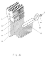
- the advantage of such an arrangement of the coupling unit 3 and such a cable routing is that a large number of flexible supply lines 17, as shown in FIG. 6, do not hinder the installation space for loom installations.
- Another advantage can be that the pressure medium acting on the decoupling device 11 is present externally, ie outside the weaving machine, and is only available for decoupling the heald frames when needed, for example when changing articles.
- connection 18 is a pressure medium connection in the case of a pneumatically or hydraulically actuated slide unit 13, 14 or an electrical connection in the case of an electromagnetic drive 12.
- FIG. 5 also shows a coupling unit 1 on the bumper side in the coupled state with a coupling unit 3 on the shaft side.
- the bumper 10 is articulated in a first articulation point 30a of a bell crank 30.
- the pull rod 31 connected to a shaft drive (not shown) is articulated in a second articulation point 30b.
- the bell crank 30 is pivotally mounted in a joint 30c about its central axis 30c '.
- Each of the articulation points 30a, 30b, 30c is formed by an axle which is the articulation point for a plurality of deflection levers 30, bumpers 10 and tie rods 31.
- FIG. 6 shows a large number of coupling units 3 with a decoupling device 11 arranged one behind the other on the bumper.
- Each decoupling device has a connecting piece 16 to which a pressure medium line 17 is connected.
- the pressure medium line 17 leads to a pressure medium storage or distributor 19 which is connected via a check valve 20 and line 21 to a pressure medium source p, not shown.
Landscapes
- Engineering & Computer Science (AREA)
- Textile Engineering (AREA)
- Looms (AREA)
- Automatic Cycles, And Cycles In General (AREA)
- Preliminary Treatment Of Fibers (AREA)
Claims (11)
- Elément de couplage de lame avec un dispositif pour le désaccouplement d'une lame de pare-chocs, comprenant une unité de couplage (1) côté lame avec au moins un premier élément de couplage (2) et une unité de couplage (3) côté pare-chocs avec au moins un deuxième élément de couplage (4), sur lequel est appliqué un mécanisme de levier (6) sollicité par un ressort de traction (5) avec un levier basculant (7) présentant une extrémité libre, lequel mécanisme de levier (6) permet un accouplement des deux unités de couplage (1,3) et interdit un désaccouplement et avec lequel l'élément de couplage (4) côté pare-chocs et le mécanisme de levier (16) sont disposés entre une plaque d'appui (8) avant et une plaque d'appui (9) arrière et sont supportés par celles-ci et avec lequel également les plaques d'appui (8,9) sont reliées de façon congruente avec le pare-chocs (10), caractérisé en ce que le désaccouplement s'effectue au moyen d'un dispositif de désaccouplement (11) sollicité par un agent de pression pneumatique ou hydraulique, disposé à proximité du mécanisme de levier (6) et intégré dans l'unité de couplage côté pare-chocs, lequel dispositif est en liaison active avec le mécanisme de levier (6).
- Elément de couplage de lame avec un dispositif pour le désaccouplement d'une lame de pare-chocs, comprenant une unité de couplage (1) côté lame avec au moins un premier élément de couplage (2) et une unité de couplage (3) côté pare-chocs avec au moins un deuxième élément de couplage (4), sur lequel est appliqué un mécanisme de levier (6) sollicité par un ressort de traction (5) avec un levier basculant (7) présentant une extrémité libre, lequel mécanisme de levier (6) permet un accouplement des deux unités de couplage (1,3) et interdit un désaccouplement et avec lequel l'élément de couplage (4) côté pare-chocs et le mécanisme de levier (6) sont disposés entre une plaque d'appui (8) avant et une plaque d'appui (9) arrière et sont supportés par celles-ci et avec lequel également les plaques d'appui (8,9) sont reliées de façon congruente au pare-chocs (10), caractérisé en ce que le désaccouplement s'effectue au moyen du dispositif de désaccouplement (11) conçu comme un entraínement (12) électromagnétique et intégré dans l'unité de couplage côté pare-chocs, l'entraínement électromagnétique étant relié de façon active avec le mécanisme de levier (6).
- Accouplement de lame selon la revendication 2, caractérisé en ce que l'entraínement (12) électromagnétique est un aimant de levage.
- Accouplement de lame selon la revendication 1, caractérisé en ce que le dispositif de désaccouplement (11) comprend une boíte à tiroir (13) avec un tiroir (14) guidé à l'intérieur et à effet simple, qui présente une surface de tiroir (14a) pouvant être sollicitée par un agent de pression, l'extrémité libre d'un levier pivotant (7) avec la force démultipliée du ressort de traction (5) reposant sur la surface de tiroir (14a) faisant face à la surface de tiroir (14b).
- Accouplement de lame selon la revendication 4, caractérisé en ce que la boíte à tiroir (13) forme un guide rectangulaire pour le tiroir (14), de sorte que la course du tiroir (14) est limitée d'un côté par le côté intérieur du fond de la boíte à tiroir (13a) et d'autre part par la grandeur d'un angle de pivotement alpha du levier basculant (7) reposant sur la surface de tiroir externe (14b) et en ce que le fond (13a) du boítier de tiroir (13) présente au moins une embase (13a') extérieure pour la liaison de la boíte à tiroir (13) avec l'unité d'accouplement (3) côté pare-chocs.
- Accouplement de lame selon les revendications 4 et 5, caractérisé en ce qu'aussi bien la boíte à tiroir (13) que le tiroir (14) présentent un évidement (13b ou 14c) en forme de fente, dans lequel le levier pivotant (7) est guidé latéralement.
- Machine à tisser avec un grand nombre de lames, qui peuvent être reliées à des pare-chocs au moyen d'accouplements de lames selon l'une quelconque des revendications précédentes, chaque dispositif de désaccouplement présentant un raccordement pouvant être relié à une conduite d'alimentation, et moyennant quoi les lames se composent de lamettes et de supports latéraux, caractérisée en ce que l'unité d'accouplement (3) côté pare-chocs, qui présente un dispositif de désaccouplement (11) fonctionnant avec un aimant hydraulique ou électromagnétique, fait fonction d'unité d'accouplement côté lame et l'unité d'accouplement (1) côté lame fait fonction d'unité d'accouplement côté pare-chocs, des parties de chaque lame recevant la conduite d'alimentation (17) du dispositif de désaccouplement (11) ou formant même une conduite d'alimentation (17) lorsque la conduite d'alimentation est conçue comme une conduite de pression.
- Machine à tisser selon la revendication 7, caractérisée en ce que les parties de chaque lame sont les supports latéraux (15b) et/ou d'au moins une des lamettes (15a).
- Machine à tisser selon la revendication 7, caractérisée en ce que, sur un dispositif de désaccouplement (11) exploité avec un agent de pression, chaque lame (15) présente au moins un raccordement d'agent de pression (18) pour la liaison avec une source d'agent de pression.
- Machine à tisser selon la revendication 7, caractérisée en ce que, sur un dispositif de désaccouplement exploité avec un électro-aimant, chaque lame (15) présente au moins un raccordement d'alimentation pour un câble électrique pour la liaison avec une source de courant électrique.
- Machine à tisser avec un grand nombre de lames, qui peuvent être reliées à des pare-chocs au moyen d'accouplements de lames à base d'unités d'accouplement, caractérisée en ce que chaque unité d'accouplement côté pare-chocs possède un dispositif de désaccouplement intégré, qui présente un raccordement d'agent de pression pourvu d'une conduite d'alimentation et en ce que chaque conduite d'alimentation (17) est raccordée à un accumulateur hydraulique (19) commun, qui est en liaison avec une source d'agent de pression (p) au moyen d'une vanne d'arrêt (20) activable.
Applications Claiming Priority (2)
| Application Number | Priority Date | Filing Date | Title |
|---|---|---|---|
| DE19548848 | 1995-12-27 | ||
| DE19548848A DE19548848C1 (de) | 1995-12-27 | 1995-12-27 | Webschaftkupplung mit einer Entkupplungsvorrichtung |
Publications (3)
| Publication Number | Publication Date |
|---|---|
| EP0784111A2 EP0784111A2 (fr) | 1997-07-16 |
| EP0784111A3 EP0784111A3 (fr) | 1998-02-11 |
| EP0784111B1 true EP0784111B1 (fr) | 2002-10-02 |
Family
ID=7781499
Family Applications (1)
| Application Number | Title | Priority Date | Filing Date |
|---|---|---|---|
| EP19960118558 Expired - Lifetime EP0784111B1 (fr) | 1995-12-27 | 1996-11-20 | Elément de couplage de cadre avec dispositif de déverrouillage |
Country Status (5)
| Country | Link |
|---|---|
| US (1) | US5810055A (fr) |
| EP (1) | EP0784111B1 (fr) |
| JP (2) | JP3140386B2 (fr) |
| AT (1) | ATE225419T1 (fr) |
| DE (2) | DE19548848C1 (fr) |
Families Citing this family (15)
| Publication number | Priority date | Publication date | Assignee | Title |
|---|---|---|---|---|
| DE19640370C1 (de) * | 1996-09-30 | 1998-02-12 | Dornier Gmbh Lindauer | Webmaschine mit Vorrichtungen zum Aufnehmen und Führen von Schaftstangen |
| FR2815047B1 (fr) * | 2000-10-06 | 2003-02-07 | Staubli Sa Ets | Dispositif d'accrochage entre un cadre de lisses et un levier et metier a tisser incorporant un tel dispositif |
| DE10111017B4 (de) * | 2001-03-07 | 2006-02-02 | Lindauer Dornier Gmbh | Antrieb für die Webschäfte einer Webmaschine |
| US7131672B2 (en) * | 2002-05-03 | 2006-11-07 | Hartwell Corporation | Latch mechanism |
| JP3994897B2 (ja) * | 2003-03-18 | 2007-10-24 | 株式会社豊田自動織機 | 織機における開口装置 |
| JP2007009606A (ja) * | 2005-07-01 | 2007-01-18 | Muroto Tekkosho:Kk | パワーショベルのアタッチメント取付具の安全装置 |
| US20080053555A1 (en) * | 2006-07-19 | 2008-03-06 | Groz-Beckert Kg | Shaft drive transmission and coupling rod |
| EP1992724B1 (fr) * | 2007-05-14 | 2012-01-25 | Groz-Beckert KG | Corde à lisse pouvant être divisée en deux parties |
| EP2009157B1 (fr) * | 2007-06-26 | 2010-01-06 | Groz-Beckert KG | Dispositif d'accouplement pour un cadre à lisses |
| DE102008035928A1 (de) * | 2008-08-01 | 2010-02-04 | Assa Abloy Sicherheitstechnik Gmbh | Türöffner mit fernansteuerbarem Ventil |
| EP2573240B1 (fr) * | 2011-09-20 | 2015-05-27 | Groz-Beckert KG | Corde à lisse de sécurité à vitesse élevée |
| EP2998421B1 (fr) | 2014-09-16 | 2020-04-08 | Groz-Beckert KG | Accouplement de cadre de lisse et cadre de lisse en étant doté |
| ITUB20155435A1 (it) * | 2015-11-10 | 2016-02-10 | Itema Spa | Sistema di aggancio rapido dei quadri-licci in un telaio di tessitura |
| FR3121152B1 (fr) * | 2021-03-24 | 2024-05-03 | Staubli Sa Ets | Mécanisme de tirage pour la commande de cadres de lisses d’un métier à tisser et métier à tisser comprenant un tel mécanisme |
| EP4545693A1 (fr) * | 2023-10-26 | 2025-04-30 | Groz-Beckert KG | Support latéral, métier à tisser et procédé de couplage d'un support latéral sur un métier à tisser |
Family Cites Families (15)
| Publication number | Priority date | Publication date | Assignee | Title |
|---|---|---|---|---|
| DE2933699C3 (de) * | 1979-08-21 | 1982-02-25 | Lindauer Dornier Gmbh, 8990 Lindau | Anhängevorrichtung des Schaftzuges am Webschaftrahmen |
| CH639706A5 (de) * | 1979-09-28 | 1983-11-30 | Rueti Ag Maschf | Vorrichtung zum kuppeln eines schaftzuges mit einem webschaftrahmen. |
| FR2540898A1 (fr) * | 1983-02-16 | 1984-08-17 | Staubli Sa Ets | Dispositif d'accrochage pour la liaison semi-automatique des cadres de lisses des metiers a tisser avec les leviers destines a leur commande |
| DE3541042C1 (de) * | 1985-11-19 | 1987-01-29 | Grob & Co Ag | Vorrichtung zum Kuppeln eines Webschaftes mit einem Antriebsorgan |
| DE8717891U1 (de) * | 1987-02-21 | 1990-12-06 | Dr.-Ing. Rudolf Hell Gmbh, 2300 Kiel | Einspannvorrichtung für Bildzylinder |
| NO178181C (no) * | 1988-06-27 | 1996-02-07 | Kvaerner Brug As | Tetningsanordning ved fleksibelt strekkstagledd i et strekkstagplattformben |
| CH681374A5 (fr) * | 1989-07-07 | 1993-03-15 | Sulzer Ag | |
| IT1252301B (it) * | 1991-11-15 | 1995-06-08 | Nuovo Pignone Spa | Sistema di controllo automatico per ratiera rotativa elettronica |
| EP0598161A1 (fr) * | 1992-11-13 | 1994-05-25 | Sulzer RàTi Ag | Métier à tisser avec serrures automatiques pour les lames |
| DE59208467D1 (de) * | 1992-11-13 | 1997-06-12 | Rueti Ag Maschf | Vorrichtung zur Aufnahme von Schaftstangen und Webmaschine mit einer solchen Vorrichtung |
| DE59206671D1 (de) * | 1992-11-13 | 1996-08-01 | Rueti Ag Maschf | Vorrichtung zum An- und Abkuppeln von Webschäften und Webmaschine mit einer solchen Vorrichtung |
| EP0598167A1 (fr) * | 1992-11-17 | 1994-05-25 | Sulzer RàTi Ag | Dispositif d'accouplement d'un cadre de tissage et métier à tisser avec dispositif d'accouplement |
| EP0654552A1 (fr) * | 1993-11-24 | 1995-05-24 | Sulzer RàTi Ag | Dispositif pour l'accouplement de cadres pour lisses et métier à tisser avec un tel dispositif |
| DE4343882C1 (de) * | 1993-12-22 | 1995-01-19 | Dornier Gmbh Lindauer | Webschaftkupplung und Vorrichtung zum simultanen Öffnen und Schließen einer Vielzahl von Webschaftkupplungen in einer Webmaschine |
| JPH0941239A (ja) * | 1995-07-25 | 1997-02-10 | Toyota Autom Loom Works Ltd | 綜絖枠の着脱装置および着脱方法 |
-
1995
- 1995-12-27 DE DE19548848A patent/DE19548848C1/de not_active Expired - Fee Related
-
1996
- 1996-11-20 DE DE59609750T patent/DE59609750D1/de not_active Expired - Lifetime
- 1996-11-20 EP EP19960118558 patent/EP0784111B1/fr not_active Expired - Lifetime
- 1996-11-20 AT AT96118558T patent/ATE225419T1/de not_active IP Right Cessation
- 1996-12-23 US US08/780,056 patent/US5810055A/en not_active Expired - Lifetime
- 1996-12-25 JP JP34609996A patent/JP3140386B2/ja not_active Expired - Fee Related
-
2000
- 2000-10-16 JP JP2000314815A patent/JP3544934B2/ja not_active Expired - Fee Related
Also Published As
| Publication number | Publication date |
|---|---|
| JP3544934B2 (ja) | 2004-07-21 |
| US5810055A (en) | 1998-09-22 |
| JP2001140139A (ja) | 2001-05-22 |
| ATE225419T1 (de) | 2002-10-15 |
| EP0784111A2 (fr) | 1997-07-16 |
| JP3140386B2 (ja) | 2001-03-05 |
| JPH09209242A (ja) | 1997-08-12 |
| DE59609750D1 (de) | 2002-11-07 |
| DE19548848C1 (de) | 1996-09-12 |
| EP0784111A3 (fr) | 1998-02-11 |
Similar Documents
| Publication | Publication Date | Title |
|---|---|---|
| EP0784111B1 (fr) | Elément de couplage de cadre avec dispositif de déverrouillage | |
| DE19754658C1 (de) | Türöffner | |
| CH680522A5 (fr) | ||
| DE102009046213B4 (de) | Wechselrahmen für einen Frontlader | |
| DE102007028151A1 (de) | Ventilnadel-Betätigungseinheit für eine Heißläufervorrichtung | |
| EP0659916B1 (fr) | Elément de couplage de cadre ainsi que dispositif pour l'ouverture et la fermeture simultanée d'un grand nombre des éléments dans un métier à tisser | |
| AT394118B (de) | Vorrichtung zur gegenseitigen verriegelung der beweglichen teile wenigstens zweier elektromagnetisch gesteuerter elektrischer schaltgeraete und elektrische anlage mit einer solchen vorrichtung | |
| EP0555857A2 (fr) | Direction pour les roues arrière | |
| DE60217851T3 (de) | Fadenklemme für eine webmaschine und webmaschine mit einer solchen fadenklemme | |
| WO2024003660A1 (fr) | Appareil de commande électrique d'aiguillage | |
| DE102008014488A1 (de) | Türschloss mit ein- und auskoppelbarer Handhabe | |
| EP4183658B1 (fr) | Dispositif de verrouillage / déverrouillage d'un coupleur de véhicule ferroviaire | |
| DE102006006585B3 (de) | Wandler eines elektrischen Eingangssignals in ein pneumatisches Ausgangssignal | |
| DE102020122839A1 (de) | Schaltbare Magnetvorrichtung | |
| EP1638117B1 (fr) | Actionneur électromagnétique | |
| DE4444823C2 (de) | Kettenwirkmaschine mit auf einer Legebarre angebrachten individuell bewegbaren Fadenführern | |
| DE3051185C2 (de) | Einrichtung zur Steuerung oder Überwachung von Maschinen | |
| EP0654552A1 (fr) | Dispositif pour l'accouplement de cadres pour lisses et métier à tisser avec un tel dispositif | |
| EP1564466B1 (fr) | Soupape à siège double dans une configuration à voies multiples avec commande magnétique | |
| EP0281109B1 (fr) | Appareil à écrire comprenant un assemblage avec tête d'écriture et un support d'écriture | |
| DE102019002643B3 (de) | Vorrichtung zum Ver- und Entriegeln eines Klinkenturms | |
| EP0977222A2 (fr) | Dispositif de connexion électrique | |
| DE4335620A1 (de) | Jaquardmaschine | |
| DE102010019578A1 (de) | Türöffner | |
| DE2521970A1 (de) | Einrichtung fuer eisenbahnanlagen zum umstellen von schlankweichen |
Legal Events
| Date | Code | Title | Description |
|---|---|---|---|
| PUAI | Public reference made under article 153(3) epc to a published international application that has entered the european phase |
Free format text: ORIGINAL CODE: 0009012 |
|
| AK | Designated contracting states |
Kind code of ref document: A2 Designated state(s): AT BE CH DE DK ES FI FR GB GR IE IT LI LU MC NL PT SE |
|
| PUAL | Search report despatched |
Free format text: ORIGINAL CODE: 0009013 |
|
| AK | Designated contracting states |
Kind code of ref document: A3 Designated state(s): AT BE CH DE DK ES FI FR GB GR IE IT LI LU MC NL PT SE |
|
| 17P | Request for examination filed |
Effective date: 19980714 |
|
| 17Q | First examination report despatched |
Effective date: 20001219 |
|
| GRAG | Despatch of communication of intention to grant |
Free format text: ORIGINAL CODE: EPIDOS AGRA |
|
| GRAG | Despatch of communication of intention to grant |
Free format text: ORIGINAL CODE: EPIDOS AGRA |
|
| GRAH | Despatch of communication of intention to grant a patent |
Free format text: ORIGINAL CODE: EPIDOS IGRA |
|
| GRAH | Despatch of communication of intention to grant a patent |
Free format text: ORIGINAL CODE: EPIDOS IGRA |
|
| GRAA | (expected) grant |
Free format text: ORIGINAL CODE: 0009210 |
|
| AK | Designated contracting states |
Kind code of ref document: B1 Designated state(s): AT BE CH DE DK ES FI FR GB GR IE IT LI LU MC NL PT SE |
|
| PG25 | Lapsed in a contracting state [announced via postgrant information from national office to epo] |
Ref country code: NL Free format text: LAPSE BECAUSE OF FAILURE TO SUBMIT A TRANSLATION OF THE DESCRIPTION OR TO PAY THE FEE WITHIN THE PRESCRIBED TIME-LIMIT Effective date: 20021002 Ref country code: IE Free format text: LAPSE BECAUSE OF FAILURE TO SUBMIT A TRANSLATION OF THE DESCRIPTION OR TO PAY THE FEE WITHIN THE PRESCRIBED TIME-LIMIT Effective date: 20021002 Ref country code: GR Free format text: LAPSE BECAUSE OF FAILURE TO SUBMIT A TRANSLATION OF THE DESCRIPTION OR TO PAY THE FEE WITHIN THE PRESCRIBED TIME-LIMIT Effective date: 20021002 Ref country code: FI Free format text: LAPSE BECAUSE OF FAILURE TO SUBMIT A TRANSLATION OF THE DESCRIPTION OR TO PAY THE FEE WITHIN THE PRESCRIBED TIME-LIMIT Effective date: 20021002 |
|
| REF | Corresponds to: |
Ref document number: 225419 Country of ref document: AT Date of ref document: 20021015 Kind code of ref document: T |
|
| REG | Reference to a national code |
Ref country code: GB Ref legal event code: FG4D Free format text: NOT ENGLISH |
|
| REG | Reference to a national code |
Ref country code: CH Ref legal event code: EP |
|
| REG | Reference to a national code |
Ref country code: IE Ref legal event code: FG4D Free format text: GERMAN |
|
| REF | Corresponds to: |
Ref document number: 59609750 Country of ref document: DE Date of ref document: 20021107 |
|
| PG25 | Lapsed in a contracting state [announced via postgrant information from national office to epo] |
Ref country code: LU Free format text: LAPSE BECAUSE OF NON-PAYMENT OF DUE FEES Effective date: 20021120 Ref country code: AT Free format text: LAPSE BECAUSE OF NON-PAYMENT OF DUE FEES Effective date: 20021120 |
|
| REG | Reference to a national code |
Ref country code: CH Ref legal event code: NV Representative=s name: R. A. EGLI & CO. PATENTANWAELTE |
|
| PG25 | Lapsed in a contracting state [announced via postgrant information from national office to epo] |
Ref country code: SE Free format text: LAPSE BECAUSE OF FAILURE TO SUBMIT A TRANSLATION OF THE DESCRIPTION OR TO PAY THE FEE WITHIN THE PRESCRIBED TIME-LIMIT Effective date: 20030102 Ref country code: PT Free format text: LAPSE BECAUSE OF FAILURE TO SUBMIT A TRANSLATION OF THE DESCRIPTION OR TO PAY THE FEE WITHIN THE PRESCRIBED TIME-LIMIT Effective date: 20030102 Ref country code: DK Free format text: LAPSE BECAUSE OF FAILURE TO SUBMIT A TRANSLATION OF THE DESCRIPTION OR TO PAY THE FEE WITHIN THE PRESCRIBED TIME-LIMIT Effective date: 20030102 |
|
| GBT | Gb: translation of ep patent filed (gb section 77(6)(a)/1977) |
Effective date: 20030127 |
|
| NLV1 | Nl: lapsed or annulled due to failure to fulfill the requirements of art. 29p and 29m of the patents act | ||
| ET | Fr: translation filed | ||
| PG25 | Lapsed in a contracting state [announced via postgrant information from national office to epo] |
Ref country code: ES Free format text: LAPSE BECAUSE OF FAILURE TO SUBMIT A TRANSLATION OF THE DESCRIPTION OR TO PAY THE FEE WITHIN THE PRESCRIBED TIME-LIMIT Effective date: 20030429 |
|
| PG25 | Lapsed in a contracting state [announced via postgrant information from national office to epo] |
Ref country code: MC Free format text: LAPSE BECAUSE OF NON-PAYMENT OF DUE FEES Effective date: 20030601 |
|
| REG | Reference to a national code |
Ref country code: IE Ref legal event code: FD4D Ref document number: 0784111E Country of ref document: IE |
|
| PLBE | No opposition filed within time limit |
Free format text: ORIGINAL CODE: 0009261 |
|
| STAA | Information on the status of an ep patent application or granted ep patent |
Free format text: STATUS: NO OPPOSITION FILED WITHIN TIME LIMIT |
|
| 26N | No opposition filed |
Effective date: 20030703 |
|
| PGFP | Annual fee paid to national office [announced via postgrant information from national office to epo] |
Ref country code: GB Payment date: 20051028 Year of fee payment: 10 |
|
| GBPC | Gb: european patent ceased through non-payment of renewal fee |
Effective date: 20061120 |
|
| PG25 | Lapsed in a contracting state [announced via postgrant information from national office to epo] |
Ref country code: GB Free format text: LAPSE BECAUSE OF NON-PAYMENT OF DUE FEES Effective date: 20061120 |
|
| PGFP | Annual fee paid to national office [announced via postgrant information from national office to epo] |
Ref country code: CH Payment date: 20141120 Year of fee payment: 19 Ref country code: DE Payment date: 20141120 Year of fee payment: 19 |
|
| PGFP | Annual fee paid to national office [announced via postgrant information from national office to epo] |
Ref country code: FR Payment date: 20141118 Year of fee payment: 19 |
|
| PGFP | Annual fee paid to national office [announced via postgrant information from national office to epo] |
Ref country code: IT Payment date: 20141125 Year of fee payment: 19 |
|
| PGFP | Annual fee paid to national office [announced via postgrant information from national office to epo] |
Ref country code: BE Payment date: 20141125 Year of fee payment: 19 |
|
| REG | Reference to a national code |
Ref country code: DE Ref legal event code: R119 Ref document number: 59609750 Country of ref document: DE |
|
| REG | Reference to a national code |
Ref country code: CH Ref legal event code: PL |
|
| PG25 | Lapsed in a contracting state [announced via postgrant information from national office to epo] |
Ref country code: IT Free format text: LAPSE BECAUSE OF NON-PAYMENT OF DUE FEES Effective date: 20151120 Ref country code: LI Free format text: LAPSE BECAUSE OF NON-PAYMENT OF DUE FEES Effective date: 20151130 Ref country code: CH Free format text: LAPSE BECAUSE OF NON-PAYMENT OF DUE FEES Effective date: 20151130 |
|
| REG | Reference to a national code |
Ref country code: FR Ref legal event code: ST Effective date: 20160729 |
|
| PG25 | Lapsed in a contracting state [announced via postgrant information from national office to epo] |
Ref country code: DE Free format text: LAPSE BECAUSE OF NON-PAYMENT OF DUE FEES Effective date: 20160601 |
|
| PG25 | Lapsed in a contracting state [announced via postgrant information from national office to epo] |
Ref country code: FR Free format text: LAPSE BECAUSE OF NON-PAYMENT OF DUE FEES Effective date: 20151130 |
|
| PG25 | Lapsed in a contracting state [announced via postgrant information from national office to epo] |
Ref country code: BE Free format text: LAPSE BECAUSE OF NON-PAYMENT OF DUE FEES Effective date: 20151130 |