EP0784111A2 - Elément de couplage de cadre avec dispositif de déverrouillage - Google Patents
Elément de couplage de cadre avec dispositif de déverrouillage Download PDFInfo
- Publication number
- EP0784111A2 EP0784111A2 EP19960118558 EP96118558A EP0784111A2 EP 0784111 A2 EP0784111 A2 EP 0784111A2 EP 19960118558 EP19960118558 EP 19960118558 EP 96118558 A EP96118558 A EP 96118558A EP 0784111 A2 EP0784111 A2 EP 0784111A2
- Authority
- EP
- European Patent Office
- Prior art keywords
- coupling
- bumpers
- heald frame
- bumper
- slide
- Prior art date
- Legal status (The legal status is an assumption and is not a legal conclusion. Google has not performed a legal analysis and makes no representation as to the accuracy of the status listed.)
- Granted
Links
- 238000010168 coupling process Methods 0.000 title claims abstract description 88
- 230000008878 coupling Effects 0.000 title claims abstract description 87
- 238000005859 coupling reaction Methods 0.000 title claims abstract description 87
- 230000007246 mechanism Effects 0.000 title claims abstract description 20
- 238000009941 weaving Methods 0.000 claims description 20
- 230000004913 activation Effects 0.000 claims 1
- 230000000284 resting effect Effects 0.000 claims 1
- 230000004888 barrier function Effects 0.000 description 4
- 230000008901 benefit Effects 0.000 description 2
- 230000008859 change Effects 0.000 description 2
- 230000006378 damage Effects 0.000 description 2
- 238000009434 installation Methods 0.000 description 2
- 238000001514 detection method Methods 0.000 description 1
- 238000005516 engineering process Methods 0.000 description 1
- 239000000835 fiber Substances 0.000 description 1
- 239000012530 fluid Substances 0.000 description 1
- 230000009760 functional impairment Effects 0.000 description 1
- 238000004519 manufacturing process Methods 0.000 description 1
- 239000000463 material Substances 0.000 description 1
Images


Classifications
-
- D—TEXTILES; PAPER
- D03—WEAVING
- D03C—SHEDDING MECHANISMS; PATTERN CARDS OR CHAINS; PUNCHING OF CARDS; DESIGNING PATTERNS
- D03C9/00—Healds; Heald frames
- D03C9/06—Heald frames
- D03C9/0683—Arrangements or means for the linking to the drive system
-
- Y—GENERAL TAGGING OF NEW TECHNOLOGICAL DEVELOPMENTS; GENERAL TAGGING OF CROSS-SECTIONAL TECHNOLOGIES SPANNING OVER SEVERAL SECTIONS OF THE IPC; TECHNICAL SUBJECTS COVERED BY FORMER USPC CROSS-REFERENCE ART COLLECTIONS [XRACs] AND DIGESTS
- Y10—TECHNICAL SUBJECTS COVERED BY FORMER USPC
- Y10T—TECHNICAL SUBJECTS COVERED BY FORMER US CLASSIFICATION
- Y10T292/00—Closure fasteners
- Y10T292/68—Keepers
- Y10T292/696—With movable dog, catch or striker
- Y10T292/699—Motor controlled
-
- Y—GENERAL TAGGING OF NEW TECHNOLOGICAL DEVELOPMENTS; GENERAL TAGGING OF CROSS-SECTIONAL TECHNOLOGIES SPANNING OVER SEVERAL SECTIONS OF THE IPC; TECHNICAL SUBJECTS COVERED BY FORMER USPC CROSS-REFERENCE ART COLLECTIONS [XRACs] AND DIGESTS
- Y10—TECHNICAL SUBJECTS COVERED BY FORMER USPC
- Y10T—TECHNICAL SUBJECTS COVERED BY FORMER US CLASSIFICATION
- Y10T403/00—Joints and connections
- Y10T403/22—Joints and connections with fluid pressure responsive component
-
- Y—GENERAL TAGGING OF NEW TECHNOLOGICAL DEVELOPMENTS; GENERAL TAGGING OF CROSS-SECTIONAL TECHNOLOGIES SPANNING OVER SEVERAL SECTIONS OF THE IPC; TECHNICAL SUBJECTS COVERED BY FORMER USPC CROSS-REFERENCE ART COLLECTIONS [XRACs] AND DIGESTS
- Y10—TECHNICAL SUBJECTS COVERED BY FORMER USPC
- Y10T—TECHNICAL SUBJECTS COVERED BY FORMER US CLASSIFICATION
- Y10T403/00—Joints and connections
- Y10T403/59—Manually releaseable latch type
- Y10T403/591—Manually releaseable latch type having operating mechanism
- Y10T403/595—Lever
Definitions
- the invention relates to a heald frame coupling with a device for uncoupling a heald frame from bumpers and further to a weaving machine with a plurality of heald frames which can be uncoupled simultaneously from the bumpers.
- Such heald frame couplings consist of a heald frame side coupling unit with at least one first coupling element and a push rod side coupling unit with at least one second coupling element, on which a lever mechanism loaded by a tension spring engages with a swivel lever having a free end.
- the lever mechanism allows the two coupling units to be coupled and prevents these units from being uncoupled.
- the heald frames are lifted out of the weaving machine or inserted into them in the manner of a so-called shaft package.
- DE-PS 43 43 882 C1 also discloses a device for the simultaneous opening of a plurality of the heald frame couplings described in the aforementioned patent specification.
- Such a device consists of a rotationally driven actuating shaft which extends across the total number of individual shafts transversely to their lifting movement.
- On the actuating shaft is assigned an actuating element for decoupling each bumper-side coupling unit. All actuators are non-rotatably connected to the control shaft and can be simultaneously connected to the lever mechanism of each clutch unit on the bumper.
- Such a decoupling device is expensive both in terms of material and production technology and on the assembly side.
- a first object of the invention is to provide a decoupling device for a heald frame coupling which is known per se and which, compared to the known decoupling device, consists comparatively of a small number of individual parts and which, while maintaining a high level of functional reliability, can be produced inexpensively.
- a second object of the invention is to arrange, in a weaving machine with a large number of heald frames, which are connected to the bumpers via heald frame couplings with an integrated decoupling device, the precautions necessary for actuating the decoupling devices to be largely close to the coupling.
- a further object of the invention is to provide arrangements which, as is known, hold both the active bumpers in a coupled position in the period of an article change and the passively active bumpers in a rest position in the weaving machine.
- the invention is based on the object of taking precautions in the manner of a safety device which, in the event of a faulty pattern programming, bring the stationary bumpers into operation by stopping the weaving machine drive.
- the tasks are characterized by the features of the independent Claims resolved.
- Each heald frame of a weaving machine is known to have shaft-side coupling means for its actuation, which can be coupled with so-called bumper-side coupling units.
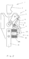
- the coupling element 2 of the shaft-side coupling unit 1 is shown as its main component.
- the coupling element 2 is disengaged from the coupling unit 3.
- Such coupling units are known in principle from DE-PS 43 43 882 C1. What is not known is a coupling unit with an integrated decoupling device.
- the decoupling device 11 consists of a slide housing 13 with a slide 14 which can be moved longitudinally therein and which has a slide surface 14a which can be acted upon by pressure medium and a slide surface 14b opposite the slide surface 14a.
- the slide surface 14a can be acted upon with pressure medium via at least one inlet 13c provided in the slide housing base 13a.
- the free end of the pivot lever 7 of the coupling unit 3 rests on the slide surface 14b with the tensioning force of the tension spring 5.
- Slider housing 13 and slider 14 have a recess 13b and 14c for engagement of the lever arm of pivot lever 7 in the decoupling device 11. These cutouts also serve as lateral guides for the pivot lever 7.
- the decoupling device 11 consists, for example, of the slide housing base 13a and of the actual slide housing 13, in which the slide 14 is received.
- the heald frame coupling with decoupling device works as follows:
- the decoupling device 11 is designed as an electromagnetic drive 12 for the pivot lever 7.
- the free end of the pivot lever 7 is applied the front end face of a magnetic core 12b which is displaceable in a coil 12a which can be excited by means of electrical energy.
- the swiveling lever 7 can be moved into the position shown in broken lines by a lifting movement of the magnetic core 12b, whereby the coupling elements 2 and 4 are uncoupled. In the illustration according to FIG. 2, the magnet coil is not excited.
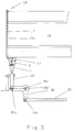
- the coupling unit 3 on the bumper side according to FIGS. 1 and 2 is used as the coupling unit on the shaft side.
- the coupling unit 3 with the decoupling device 11 is connected here by means of screws 29 to the shaft rod 15a of a heald frame 15.
- the supply line 17 leading to the connecting piece 16 is guided through the respective right and / or left side support 15a of the respective heald frame 15.
- the beginning of the supply line is connected to a pressure medium connection 18, which is arranged at the upper free end of the side support 15b; see also Figure 5.
- a further advantage can be that the pressure medium acting on the decoupling device 11 is present externally, ie outside the weaving machine, and is only available for decoupling the heald frames when needed, for example when changing articles.
- connection 18 is in the case of a pneumatically or hydraulically actuated slide unit 13, 14 a pressure medium connection or in the case of training as electromagnetic drive 12 an electrical connection.
- FIG. 5 also shows a coupling unit 1 on the bumper side in the coupled state with a coupling unit 3 on the shaft side.
- the bumper 10 is articulated in a first articulation point 30a of a bell crank 30.
- the pull rod 31 connected to a shaft drive (not shown) is articulated in a second articulation point 30b.
- the bell crank 30 is pivotally mounted in a joint 30c about its central axis 30c '.
- Each of the articulation points 30a, 30b, 30c is formed by an axle, which is the articulation point for a plurality of deflection levers 30, bumpers 10 and tie rods 31; see also Figure 8.
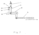
- FIG. 6 shows a large number of coupling units 3 with a decoupling device 11 arranged one behind the other on the bumper.
- Each decoupling device has a connecting piece 16 to which a pressure medium line 17 is connected.
- the pressure medium line 17 leads to a pressure medium storage or distributor 19 which is connected via a check valve 20 and line 21 to a pressure medium source p, not shown.
- each bumper 10 has a provision 22 in the form of a holding element below its coupling unit 1 or 3.
- Each of these precautions interacts with a first or second holding device 23 or 24 provided on a machine-fixed carrier 32.
- the carrier 32 with its holding devices 23, 24 extends within the weaving machine over the multiplicity of the outer left shaft draws arranged one behind the other and formed from the main components 1 or 3, 11 and 10, 30, 31.
- the purpose of the holding device 23 is, in the case of uncoupling or coupling the Heald frames 15 from or with the shaft pulls to lock all actively operating bumpers 10, ie all bumpers to be coupled or to be uncoupled from the heald frames in a coupled position.
- FIG. 8 shows a large number of the passively active bumpers 10, which are locked on the holder 24 via the arrangement 22. Now it may happen that the programmer makes a mistake during the pattern programming, in such a way that, contrary to the pattern program, one or more passively active shaft pulls are activated by the shaft drive. Such an error leads, if there are no appropriate precautions for error detection and start-up of the weaving machine is not prevented, to the destruction or at least considerable damage to functional units of the weaving machine. If corresponding precautions are not taken, a safety device 25 is provided for the passively active bumpers 10, which consists, for example, of an opto-electric barrier known per se, which has a pivoting range of the bumpers 10 between the holding devices 23, 24 and the position of the barrier supervised.
- a safety device 25 is provided for the passively active bumpers 10, which consists, for example, of an opto-electric barrier known per se, which has a pivoting range of the bumpers 10 between the holding devices 23, 24 and the position of the barrier supervised.
- a safety device 25 can be provided, which consists of a mechanical means located in the swiveling range of the bumpers 10, which is effective on a switch 26 connected to the weaving machine drive.
- the mechanical means can run transversely to the bumpers 10 be a rigid or flexible element 27 which triggers a signal stopping the drive of the weaving machine when one of the passively active bumpers 10 is contacted at the switch 26.
Landscapes
- Engineering & Computer Science (AREA)
- Textile Engineering (AREA)
- Looms (AREA)
- Automatic Cycles, And Cycles In General (AREA)
- Preliminary Treatment Of Fibers (AREA)
Applications Claiming Priority (2)
| Application Number | Priority Date | Filing Date | Title |
|---|---|---|---|
| DE19548848 | 1995-12-27 | ||
| DE19548848A DE19548848C1 (de) | 1995-12-27 | 1995-12-27 | Webschaftkupplung mit einer Entkupplungsvorrichtung |
Publications (3)
| Publication Number | Publication Date |
|---|---|
| EP0784111A2 true EP0784111A2 (fr) | 1997-07-16 |
| EP0784111A3 EP0784111A3 (fr) | 1998-02-11 |
| EP0784111B1 EP0784111B1 (fr) | 2002-10-02 |
Family
ID=7781499
Family Applications (1)
| Application Number | Title | Priority Date | Filing Date |
|---|---|---|---|
| EP19960118558 Expired - Lifetime EP0784111B1 (fr) | 1995-12-27 | 1996-11-20 | Elément de couplage de cadre avec dispositif de déverrouillage |
Country Status (5)
| Country | Link |
|---|---|
| US (1) | US5810055A (fr) |
| EP (1) | EP0784111B1 (fr) |
| JP (2) | JP3140386B2 (fr) |
| AT (1) | ATE225419T1 (fr) |
| DE (2) | DE19548848C1 (fr) |
Families Citing this family (15)
| Publication number | Priority date | Publication date | Assignee | Title |
|---|---|---|---|---|
| DE19640370C1 (de) * | 1996-09-30 | 1998-02-12 | Dornier Gmbh Lindauer | Webmaschine mit Vorrichtungen zum Aufnehmen und Führen von Schaftstangen |
| FR2815047B1 (fr) * | 2000-10-06 | 2003-02-07 | Staubli Sa Ets | Dispositif d'accrochage entre un cadre de lisses et un levier et metier a tisser incorporant un tel dispositif |
| DE10111017B4 (de) * | 2001-03-07 | 2006-02-02 | Lindauer Dornier Gmbh | Antrieb für die Webschäfte einer Webmaschine |
| US7131672B2 (en) * | 2002-05-03 | 2006-11-07 | Hartwell Corporation | Latch mechanism |
| JP3994897B2 (ja) * | 2003-03-18 | 2007-10-24 | 株式会社豊田自動織機 | 織機における開口装置 |
| JP2007009606A (ja) * | 2005-07-01 | 2007-01-18 | Muroto Tekkosho:Kk | パワーショベルのアタッチメント取付具の安全装置 |
| US20080053555A1 (en) * | 2006-07-19 | 2008-03-06 | Groz-Beckert Kg | Shaft drive transmission and coupling rod |
| EP1992724B1 (fr) * | 2007-05-14 | 2012-01-25 | Groz-Beckert KG | Corde à lisse pouvant être divisée en deux parties |
| EP2009157B1 (fr) * | 2007-06-26 | 2010-01-06 | Groz-Beckert KG | Dispositif d'accouplement pour un cadre à lisses |
| DE102008035928A1 (de) * | 2008-08-01 | 2010-02-04 | Assa Abloy Sicherheitstechnik Gmbh | Türöffner mit fernansteuerbarem Ventil |
| EP2573240B1 (fr) * | 2011-09-20 | 2015-05-27 | Groz-Beckert KG | Corde à lisse de sécurité à vitesse élevée |
| EP2998421B1 (fr) | 2014-09-16 | 2020-04-08 | Groz-Beckert KG | Accouplement de cadre de lisse et cadre de lisse en étant doté |
| ITUB20155435A1 (it) * | 2015-11-10 | 2016-02-10 | Itema Spa | Sistema di aggancio rapido dei quadri-licci in un telaio di tessitura |
| FR3121152B1 (fr) * | 2021-03-24 | 2024-05-03 | Staubli Sa Ets | Mécanisme de tirage pour la commande de cadres de lisses d’un métier à tisser et métier à tisser comprenant un tel mécanisme |
| EP4545693A1 (fr) * | 2023-10-26 | 2025-04-30 | Groz-Beckert KG | Support latéral, métier à tisser et procédé de couplage d'un support latéral sur un métier à tisser |
Citations (1)
| Publication number | Priority date | Publication date | Assignee | Title |
|---|---|---|---|---|
| DE4343882C1 (de) | 1993-12-22 | 1995-01-19 | Dornier Gmbh Lindauer | Webschaftkupplung und Vorrichtung zum simultanen Öffnen und Schließen einer Vielzahl von Webschaftkupplungen in einer Webmaschine |
Family Cites Families (14)
| Publication number | Priority date | Publication date | Assignee | Title |
|---|---|---|---|---|
| DE2933699C3 (de) * | 1979-08-21 | 1982-02-25 | Lindauer Dornier Gmbh, 8990 Lindau | Anhängevorrichtung des Schaftzuges am Webschaftrahmen |
| CH639706A5 (de) * | 1979-09-28 | 1983-11-30 | Rueti Ag Maschf | Vorrichtung zum kuppeln eines schaftzuges mit einem webschaftrahmen. |
| FR2540898A1 (fr) * | 1983-02-16 | 1984-08-17 | Staubli Sa Ets | Dispositif d'accrochage pour la liaison semi-automatique des cadres de lisses des metiers a tisser avec les leviers destines a leur commande |
| DE3541042C1 (de) * | 1985-11-19 | 1987-01-29 | Grob & Co Ag | Vorrichtung zum Kuppeln eines Webschaftes mit einem Antriebsorgan |
| DE8717891U1 (de) * | 1987-02-21 | 1990-12-06 | Dr.-Ing. Rudolf Hell Gmbh, 2300 Kiel | Einspannvorrichtung für Bildzylinder |
| NO178181C (no) * | 1988-06-27 | 1996-02-07 | Kvaerner Brug As | Tetningsanordning ved fleksibelt strekkstagledd i et strekkstagplattformben |
| CH681374A5 (fr) * | 1989-07-07 | 1993-03-15 | Sulzer Ag | |
| IT1252301B (it) * | 1991-11-15 | 1995-06-08 | Nuovo Pignone Spa | Sistema di controllo automatico per ratiera rotativa elettronica |
| EP0598161A1 (fr) * | 1992-11-13 | 1994-05-25 | Sulzer RàTi Ag | Métier à tisser avec serrures automatiques pour les lames |
| DE59208467D1 (de) * | 1992-11-13 | 1997-06-12 | Rueti Ag Maschf | Vorrichtung zur Aufnahme von Schaftstangen und Webmaschine mit einer solchen Vorrichtung |
| DE59206671D1 (de) * | 1992-11-13 | 1996-08-01 | Rueti Ag Maschf | Vorrichtung zum An- und Abkuppeln von Webschäften und Webmaschine mit einer solchen Vorrichtung |
| EP0598167A1 (fr) * | 1992-11-17 | 1994-05-25 | Sulzer RàTi Ag | Dispositif d'accouplement d'un cadre de tissage et métier à tisser avec dispositif d'accouplement |
| EP0654552A1 (fr) * | 1993-11-24 | 1995-05-24 | Sulzer RàTi Ag | Dispositif pour l'accouplement de cadres pour lisses et métier à tisser avec un tel dispositif |
| JPH0941239A (ja) * | 1995-07-25 | 1997-02-10 | Toyota Autom Loom Works Ltd | 綜絖枠の着脱装置および着脱方法 |
-
1995
- 1995-12-27 DE DE19548848A patent/DE19548848C1/de not_active Expired - Fee Related
-
1996
- 1996-11-20 DE DE59609750T patent/DE59609750D1/de not_active Expired - Lifetime
- 1996-11-20 EP EP19960118558 patent/EP0784111B1/fr not_active Expired - Lifetime
- 1996-11-20 AT AT96118558T patent/ATE225419T1/de not_active IP Right Cessation
- 1996-12-23 US US08/780,056 patent/US5810055A/en not_active Expired - Lifetime
- 1996-12-25 JP JP34609996A patent/JP3140386B2/ja not_active Expired - Fee Related
-
2000
- 2000-10-16 JP JP2000314815A patent/JP3544934B2/ja not_active Expired - Fee Related
Patent Citations (1)
| Publication number | Priority date | Publication date | Assignee | Title |
|---|---|---|---|---|
| DE4343882C1 (de) | 1993-12-22 | 1995-01-19 | Dornier Gmbh Lindauer | Webschaftkupplung und Vorrichtung zum simultanen Öffnen und Schließen einer Vielzahl von Webschaftkupplungen in einer Webmaschine |
Also Published As
| Publication number | Publication date |
|---|---|
| JP3544934B2 (ja) | 2004-07-21 |
| US5810055A (en) | 1998-09-22 |
| JP2001140139A (ja) | 2001-05-22 |
| ATE225419T1 (de) | 2002-10-15 |
| JP3140386B2 (ja) | 2001-03-05 |
| JPH09209242A (ja) | 1997-08-12 |
| DE59609750D1 (de) | 2002-11-07 |
| DE19548848C1 (de) | 1996-09-12 |
| EP0784111B1 (fr) | 2002-10-02 |
| EP0784111A3 (fr) | 1998-02-11 |
Similar Documents
| Publication | Publication Date | Title |
|---|---|---|
| EP0784111A2 (fr) | Elément de couplage de cadre avec dispositif de déverrouillage | |
| DE69400564T2 (de) | Servozylindervorrichtung | |
| CH680522A5 (fr) | ||
| WO2013068984A1 (fr) | Dispositif de transport pour lignes | |
| DE112020002292T5 (de) | Greifer mit Sensor für Industriemanipulatoren und Verfahren zum Erfassen der Anwesenheit eines Werkstücks zwischen den Backen eines Greifers für Industriemanipulatoren | |
| DE2921464A1 (de) | Steuersysteme | |
| AT394118B (de) | Vorrichtung zur gegenseitigen verriegelung der beweglichen teile wenigstens zweier elektromagnetisch gesteuerter elektrischer schaltgeraete und elektrische anlage mit einer solchen vorrichtung | |
| EP0445374B1 (fr) | Dispositif d'enlèvement de bobines et de la mise en place de tubes de bobines dans les métiers à filer ou à retordre | |
| WO2006002995A1 (fr) | Mecanisme de prehension pneumatique | |
| EP2037023A1 (fr) | Pince-fil pour une tête de pince et son procédé de fonctionnement | |
| EP0617744B1 (fr) | Dispositif de commande pour un fil d'une machine textile | |
| WO2024003660A1 (fr) | Appareil de commande électrique d'aiguillage | |
| DE19632181C1 (de) | Spreader mit Twistlocks für Container mit Eckbeschlägen | |
| EP0634512A1 (fr) | Commande et entrainement d'unités de broderie | |
| DE102020131035A1 (de) | Lineares Transportsystem mit Objektübergabe | |
| EP3511459B1 (fr) | Métier à tricoter à chaîne | |
| DE3607530C2 (fr) | ||
| EP3511460B1 (fr) | Métier à tricoter à chaîne et procédé d'assistance à l'utilisateur pour métier à tricoter à chaîne | |
| DE2722895C3 (de) | Automatischer Spulenwechsler für eine Spinnmaschine o.dgl | |
| DE1576075A1 (de) | Hydraulische Betaetigungsvorrichtung | |
| EP0654552A1 (fr) | Dispositif pour l'accouplement de cadres pour lisses et métier à tisser avec un tel dispositif | |
| DE3051184C2 (de) | Einrichtung zur Steuerung oder Überwachung von Maschinen | |
| DE2826317A1 (de) | Bremsvorrichtung fuer eine webmaschine | |
| EP1100986A1 (fr) | Changement rapide de machines de formation de la foule sur metiers a tisser a ratiere, et dispositif de changement rapide | |
| AT407356B (de) | Sicherheitseinrichtung |
Legal Events
| Date | Code | Title | Description |
|---|---|---|---|
| PUAI | Public reference made under article 153(3) epc to a published international application that has entered the european phase |
Free format text: ORIGINAL CODE: 0009012 |
|
| AK | Designated contracting states |
Kind code of ref document: A2 Designated state(s): AT BE CH DE DK ES FI FR GB GR IE IT LI LU MC NL PT SE |
|
| PUAL | Search report despatched |
Free format text: ORIGINAL CODE: 0009013 |
|
| AK | Designated contracting states |
Kind code of ref document: A3 Designated state(s): AT BE CH DE DK ES FI FR GB GR IE IT LI LU MC NL PT SE |
|
| 17P | Request for examination filed |
Effective date: 19980714 |
|
| 17Q | First examination report despatched |
Effective date: 20001219 |
|
| GRAG | Despatch of communication of intention to grant |
Free format text: ORIGINAL CODE: EPIDOS AGRA |
|
| GRAG | Despatch of communication of intention to grant |
Free format text: ORIGINAL CODE: EPIDOS AGRA |
|
| GRAH | Despatch of communication of intention to grant a patent |
Free format text: ORIGINAL CODE: EPIDOS IGRA |
|
| GRAH | Despatch of communication of intention to grant a patent |
Free format text: ORIGINAL CODE: EPIDOS IGRA |
|
| GRAA | (expected) grant |
Free format text: ORIGINAL CODE: 0009210 |
|
| AK | Designated contracting states |
Kind code of ref document: B1 Designated state(s): AT BE CH DE DK ES FI FR GB GR IE IT LI LU MC NL PT SE |
|
| PG25 | Lapsed in a contracting state [announced via postgrant information from national office to epo] |
Ref country code: NL Free format text: LAPSE BECAUSE OF FAILURE TO SUBMIT A TRANSLATION OF THE DESCRIPTION OR TO PAY THE FEE WITHIN THE PRESCRIBED TIME-LIMIT Effective date: 20021002 Ref country code: IE Free format text: LAPSE BECAUSE OF FAILURE TO SUBMIT A TRANSLATION OF THE DESCRIPTION OR TO PAY THE FEE WITHIN THE PRESCRIBED TIME-LIMIT Effective date: 20021002 Ref country code: GR Free format text: LAPSE BECAUSE OF FAILURE TO SUBMIT A TRANSLATION OF THE DESCRIPTION OR TO PAY THE FEE WITHIN THE PRESCRIBED TIME-LIMIT Effective date: 20021002 Ref country code: FI Free format text: LAPSE BECAUSE OF FAILURE TO SUBMIT A TRANSLATION OF THE DESCRIPTION OR TO PAY THE FEE WITHIN THE PRESCRIBED TIME-LIMIT Effective date: 20021002 |
|
| REF | Corresponds to: |
Ref document number: 225419 Country of ref document: AT Date of ref document: 20021015 Kind code of ref document: T |
|
| REG | Reference to a national code |
Ref country code: GB Ref legal event code: FG4D Free format text: NOT ENGLISH |
|
| REG | Reference to a national code |
Ref country code: CH Ref legal event code: EP |
|
| REG | Reference to a national code |
Ref country code: IE Ref legal event code: FG4D Free format text: GERMAN |
|
| REF | Corresponds to: |
Ref document number: 59609750 Country of ref document: DE Date of ref document: 20021107 |
|
| PG25 | Lapsed in a contracting state [announced via postgrant information from national office to epo] |
Ref country code: LU Free format text: LAPSE BECAUSE OF NON-PAYMENT OF DUE FEES Effective date: 20021120 Ref country code: AT Free format text: LAPSE BECAUSE OF NON-PAYMENT OF DUE FEES Effective date: 20021120 |
|
| REG | Reference to a national code |
Ref country code: CH Ref legal event code: NV Representative=s name: R. A. EGLI & CO. PATENTANWAELTE |
|
| PG25 | Lapsed in a contracting state [announced via postgrant information from national office to epo] |
Ref country code: SE Free format text: LAPSE BECAUSE OF FAILURE TO SUBMIT A TRANSLATION OF THE DESCRIPTION OR TO PAY THE FEE WITHIN THE PRESCRIBED TIME-LIMIT Effective date: 20030102 Ref country code: PT Free format text: LAPSE BECAUSE OF FAILURE TO SUBMIT A TRANSLATION OF THE DESCRIPTION OR TO PAY THE FEE WITHIN THE PRESCRIBED TIME-LIMIT Effective date: 20030102 Ref country code: DK Free format text: LAPSE BECAUSE OF FAILURE TO SUBMIT A TRANSLATION OF THE DESCRIPTION OR TO PAY THE FEE WITHIN THE PRESCRIBED TIME-LIMIT Effective date: 20030102 |
|
| GBT | Gb: translation of ep patent filed (gb section 77(6)(a)/1977) |
Effective date: 20030127 |
|
| NLV1 | Nl: lapsed or annulled due to failure to fulfill the requirements of art. 29p and 29m of the patents act | ||
| ET | Fr: translation filed | ||
| PG25 | Lapsed in a contracting state [announced via postgrant information from national office to epo] |
Ref country code: ES Free format text: LAPSE BECAUSE OF FAILURE TO SUBMIT A TRANSLATION OF THE DESCRIPTION OR TO PAY THE FEE WITHIN THE PRESCRIBED TIME-LIMIT Effective date: 20030429 |
|
| PG25 | Lapsed in a contracting state [announced via postgrant information from national office to epo] |
Ref country code: MC Free format text: LAPSE BECAUSE OF NON-PAYMENT OF DUE FEES Effective date: 20030601 |
|
| REG | Reference to a national code |
Ref country code: IE Ref legal event code: FD4D Ref document number: 0784111E Country of ref document: IE |
|
| PLBE | No opposition filed within time limit |
Free format text: ORIGINAL CODE: 0009261 |
|
| STAA | Information on the status of an ep patent application or granted ep patent |
Free format text: STATUS: NO OPPOSITION FILED WITHIN TIME LIMIT |
|
| 26N | No opposition filed |
Effective date: 20030703 |
|
| PGFP | Annual fee paid to national office [announced via postgrant information from national office to epo] |
Ref country code: GB Payment date: 20051028 Year of fee payment: 10 |
|
| GBPC | Gb: european patent ceased through non-payment of renewal fee |
Effective date: 20061120 |
|
| PG25 | Lapsed in a contracting state [announced via postgrant information from national office to epo] |
Ref country code: GB Free format text: LAPSE BECAUSE OF NON-PAYMENT OF DUE FEES Effective date: 20061120 |
|
| PGFP | Annual fee paid to national office [announced via postgrant information from national office to epo] |
Ref country code: CH Payment date: 20141120 Year of fee payment: 19 Ref country code: DE Payment date: 20141120 Year of fee payment: 19 |
|
| PGFP | Annual fee paid to national office [announced via postgrant information from national office to epo] |
Ref country code: FR Payment date: 20141118 Year of fee payment: 19 |
|
| PGFP | Annual fee paid to national office [announced via postgrant information from national office to epo] |
Ref country code: IT Payment date: 20141125 Year of fee payment: 19 |
|
| PGFP | Annual fee paid to national office [announced via postgrant information from national office to epo] |
Ref country code: BE Payment date: 20141125 Year of fee payment: 19 |
|
| REG | Reference to a national code |
Ref country code: DE Ref legal event code: R119 Ref document number: 59609750 Country of ref document: DE |
|
| REG | Reference to a national code |
Ref country code: CH Ref legal event code: PL |
|
| PG25 | Lapsed in a contracting state [announced via postgrant information from national office to epo] |
Ref country code: IT Free format text: LAPSE BECAUSE OF NON-PAYMENT OF DUE FEES Effective date: 20151120 Ref country code: LI Free format text: LAPSE BECAUSE OF NON-PAYMENT OF DUE FEES Effective date: 20151130 Ref country code: CH Free format text: LAPSE BECAUSE OF NON-PAYMENT OF DUE FEES Effective date: 20151130 |
|
| REG | Reference to a national code |
Ref country code: FR Ref legal event code: ST Effective date: 20160729 |
|
| PG25 | Lapsed in a contracting state [announced via postgrant information from national office to epo] |
Ref country code: DE Free format text: LAPSE BECAUSE OF NON-PAYMENT OF DUE FEES Effective date: 20160601 |
|
| PG25 | Lapsed in a contracting state [announced via postgrant information from national office to epo] |
Ref country code: FR Free format text: LAPSE BECAUSE OF NON-PAYMENT OF DUE FEES Effective date: 20151130 |
|
| PG25 | Lapsed in a contracting state [announced via postgrant information from national office to epo] |
Ref country code: BE Free format text: LAPSE BECAUSE OF NON-PAYMENT OF DUE FEES Effective date: 20151130 |