EP0784112A1 - Magasin pour lisses en fil métallique - Google Patents
Magasin pour lisses en fil métallique Download PDFInfo
- Publication number
- EP0784112A1 EP0784112A1 EP97100365A EP97100365A EP0784112A1 EP 0784112 A1 EP0784112 A1 EP 0784112A1 EP 97100365 A EP97100365 A EP 97100365A EP 97100365 A EP97100365 A EP 97100365A EP 0784112 A1 EP0784112 A1 EP 0784112A1
- Authority
- EP
- European Patent Office
- Prior art keywords
- wire
- healdes
- heald
- stocker
- ring
- Prior art date
- Legal status (The legal status is an assumption and is not a legal conclusion. Google has not performed a legal analysis and makes no representation as to the accuracy of the status listed.)
- Withdrawn
Links
- 238000007599 discharging Methods 0.000 claims abstract description 6
- 210000000078 claw Anatomy 0.000 claims description 71
- 238000007664 blowing Methods 0.000 claims description 2
- 230000006835 compression Effects 0.000 description 6
- 238000007906 compression Methods 0.000 description 6
- 238000003780 insertion Methods 0.000 description 6
- 230000037431 insertion Effects 0.000 description 6
- 210000002105 tongue Anatomy 0.000 description 5
- 238000005299 abrasion Methods 0.000 description 3
- 229910000831 Steel Inorganic materials 0.000 description 2
- 230000000694 effects Effects 0.000 description 2
- 238000012986 modification Methods 0.000 description 2
- 230000004048 modification Effects 0.000 description 2
- 230000002093 peripheral effect Effects 0.000 description 2
- 238000000926 separation method Methods 0.000 description 2
- 239000010959 steel Substances 0.000 description 2
- 238000009941 weaving Methods 0.000 description 2
- OKTJSMMVPCPJKN-UHFFFAOYSA-N Carbon Chemical compound [C] OKTJSMMVPCPJKN-UHFFFAOYSA-N 0.000 description 1
- VYZAMTAEIAYCRO-UHFFFAOYSA-N Chromium Chemical compound [Cr] VYZAMTAEIAYCRO-UHFFFAOYSA-N 0.000 description 1
- XEEYBQQBJWHFJM-UHFFFAOYSA-N Iron Chemical group [Fe] XEEYBQQBJWHFJM-UHFFFAOYSA-N 0.000 description 1
- 229910052782 aluminium Inorganic materials 0.000 description 1
- XAGFODPZIPBFFR-UHFFFAOYSA-N aluminium Chemical compound [Al] XAGFODPZIPBFFR-UHFFFAOYSA-N 0.000 description 1
- 229910052799 carbon Inorganic materials 0.000 description 1
- 229910052804 chromium Inorganic materials 0.000 description 1
- 239000011651 chromium Substances 0.000 description 1
- 230000003247 decreasing effect Effects 0.000 description 1
- 238000005516 engineering process Methods 0.000 description 1
- 230000002708 enhancing effect Effects 0.000 description 1
- 230000001788 irregular Effects 0.000 description 1
- 230000009191 jumping Effects 0.000 description 1
- 229910052751 metal Inorganic materials 0.000 description 1
- 239000002184 metal Substances 0.000 description 1
- 238000007747 plating Methods 0.000 description 1
- 230000003252 repetitive effect Effects 0.000 description 1
- 238000004381 surface treatment Methods 0.000 description 1
Images


Classifications
-
- D—TEXTILES; PAPER
- D03—WEAVING
- D03J—AUXILIARY WEAVING APPARATUS; WEAVERS' TOOLS; SHUTTLES
- D03J1/00—Auxiliary apparatus combined with or associated with looms
- D03J1/14—Apparatus for threading warp stop-motion droppers, healds, or reeds
-
- D—TEXTILES; PAPER
- D03—WEAVING
- D03C—SHEDDING MECHANISMS; PATTERN CARDS OR CHAINS; PUNCHING OF CARDS; DESIGNING PATTERNS
- D03C9/00—Healds; Heald frames
- D03C9/02—Healds
- D03C9/024—Eyelets
-
- D—TEXTILES; PAPER
- D03—WEAVING
- D03D—WOVEN FABRICS; METHODS OF WEAVING; LOOMS
- D03D41/00—Looms not otherwise provided for, e.g. for weaving chenille yarn; Details peculiar to these looms
-
- D—TEXTILES; PAPER
- D03—WEAVING
- D03D—WOVEN FABRICS; METHODS OF WEAVING; LOOMS
- D03D49/00—Details or constructional features not specially adapted for looms of a particular type
Definitions
- the present invention relates to a stocker for wire healdes utilized in a warp passing apparatus for passing a warp through a mail of wire heald.
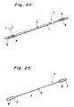
- a flat heald A is integrally made of SUS 420 or the like having a spring property and, as shown in Fig. 22, has a flat, slender rod portion 1 of a rectangular cross section, a mail 2 is formed at the middle of this rod portion 1, ring portions 3 are provided at the both ends of this rod portion 1, and a guide hole 4 of an elongate hole shape is formed in each ring portion 3. Further, this flat heald A bends easily in the direction of an arrow, has characteristics of being strong against torsion and being resistant to deformation, and is excellent in durability.
- the wire healdes B are made of hard drawn steel wire (60 carbon) and, as shown in Fig. 23, a wire heald has a slender rod portion 5, a mail 6 is formed at the middle of this rod portion 5, ring portions 7 are provided at the both ends of this rod portion 5, and a guide hole 8 is formed in an elongate hole shape in each ring portion 7.
- this wire heald B has characteristics of being very light in weight, easy to handle, and cheap.
- the wire healdes B are very easy to bend, and this ease to bend causes them to become tangled with each other, resulting in a drawback of being hard to handle.
- the wire healdes B are kept in a suspended state, and then the ease to bend does harm to the wire healdes B so as to cause a mutually tangled state. Accordingly, the wire healdes B are arranged in correct order near the ring portions 7 in which the magazine bars are inserted, whereas they are tangled with each other near the mails 6 to be arranged in irregular order. As a result, it is a present status that the wire healdes B cannot be drawn out as being separated one by one from the tip of the magazine bars because of entanglement among the wire healdes B and because they are thin wires.
- the conventional stocker for flat healdes employs the magazine bars extending horizontally with one end being fixed to the platelike fixed member and with the other end being a free end. Therefore, for refilling flat healdes A into the stocker, the refilling operation of flat healdes A is not easy as it is hindered by a chuck mechanism for drive of healdes disposed in front of the free ends of the magazine bars. Namely, at the magazine bars extending horizontally, the end for refilling of flat healdes A results in coinciding with the end for drawing-out of flat healdes A, which makes the refilling operation of flat healdes A difficult. For employing such an arrangement as to perform the refilling of flat healdes A with every magazine bars, a new arrangement for mounting and dismounting the magazine bars becomes necessary, which would be disadvantageous in terms of cost and structure.
- the present invention has been accomplished in order to solve the above problems, and a specific object of the present invention is to provide a stocker for wire healdes which insures stable stocking of wire healdes and which also facilitates the refilling operation.
- a stocker for wire healdes is a stocker for wire healdes, which, in order to selectively discharge an arbitrary wire heald out of a lot of wire healdes juxtaposed, is arranged to stock a lot of the wire healdes, wherein the wire healdes kept in a horizontal state are stacked vertically in a housing, a heald refilling aperture is provided at a top portion of the housing, and a heald drawing opening for discharging the lowermost of the wire healdes stacked is provided at a lower front end in the housing.
- the wire healdes are stacked vertically in the housing as being maintained in a horizontal state, whereby the heald refilling aperture can be provided at the top portion of the housing and the heald drawing opening can be provided at the lower front end of the housing.
- the aperture for refilling the wire healdes and the opening for discharging the wire healdes from the housing can be provided separately in the housing, which, upon the refilling operation of wire healdes, permits the refilling operation to be performed from above the housing as utilizing the self-weight of healdes or the like, thereby facilitating the filling operation of wire healdes.
- provision of the heald refilling aperture at the top portion of the housing permits one to perform the refilling operation as looking into this aperture from the top.
- provision of the heald drawing opening at the lower front end of the housing permits the guide hole of the lowermost wire heald to be hooked on a pin or the like, whereby the wire heald can be drawn horizontally as being maintained horizontal.
- a pair of front and rear floating rods inserted through either guide hole of a pair of ring portions formed at the both ends of the wire healdes and extending vertically, are disposed in the housing, lower end faces of the floating rods are disposed in contact with a heald receiving bottom surface of the housing, and the floating rods are arranged to travel vertically in the housing, whereby entanglement of wire healdes can be prevented in the stocker.
- a tapered ring lead-in portion for leading the ring portion into between the lower end face of the floating rod and the heald receiving bottom surface is formed at a rear part in the lower end face of the floating rod.
- a horizontally cut ring lead-in portion is formed at a rear and a front parts in the lower end face of the floating rod in order to pull the ring portion to between the lower end face of the floating rod and the heald receiving bottom surface.
- the housing is provided with a heald front end separating portion having a pair of right and left push claws disposed below the front-side floating rod and arranged to engage with the ring portion of the wire heald in which the front-side floating rod is inserted and with the lower end face of the front-side floating rod to push the front-side ring portion and the front-side floating rod up from the bottom.
- each push claw comprises a claw portion extending horizontally to engage with the lower end face of the floating rod and with the ring portion, and a support portion for supporting this claw portion and wherein tip portions of the claw portions located right and left are spaced from each other.
- a taper surface is formed at the tip of the claw portion, a claw engaging recess for the tip portion of the claw portion to be inserted therein is formed in the lower end face of the floating rod, and a taper surface fitting with the taper surface of the claw portion is formed in an upper surface of the claw engaging recess.
- the heald front end separating portion has a base portion for keeping the push claws standing and a spring disposed between the base portion and a base of the housing and arranged to urge the base portion in a direction to depart from the base and wherein the base portion is moved vertically by driving means.
- the housing is provided with a heald rear end separating portion having a lift member disposed below the rear-side floating rod and arranged to engage with the ring portion of the wire heald in which the rear-side floating rod is inserted and with the lower end face of the rear-side floating rod to push the rear-side ring portion and rear-side floating rod up from the bottom.
- the heald rear end separating portion has a base portion for keeping the lift member standing and a spring disposed between the base portion and a base of the housing and arranged to urge the base portion in a direction to depart from the base and wherein the base portion is moved vertically by driving means.
- ring receiving portions for receiving the floating rods are provided at the both ends of the housing.
- an air blow-off port for blowing off compressed air toward the floating rod obliquely from thereabove is provided in an upper part of the ring receiving portion and an air catch recess opposed to the air blow-off port to catch the compressed air from the air blow-off port is formed in an upper part of the floating rod.
- an air suction portion for sucking the ring portions of the wire healdes mounted on the floating rod backward is provided in a lower part of the ring receiving portion located in a rear part of the housing.
- the housing is provided with a rod receiving slit for receiving rod portions of the wire healdes.
- a ring guide hole for enabling horizontal drawing of the ring portion of the lowermost wire heald is formed at a lower end of the rod receiving slit by expanding the rod receiving slit horizontally.
- the housing has a mail receiving space portion for receiving mails of the wire healdes at a position where the rod receiving slit is separated into front and rear slits and wherein a heald escape recess is formed in the heald receiving bottom surface to expand a lower part of the mail receiving space portion.
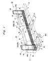
- Fig. 1 is a perspective view to show a horizontal placement type stocker for wire healdes according to the present embodiment.
- the wire heald stocker 10 shown in the same figure has a housing 11 for keeping the wire healdes B horizontal and layered in a vertical stack.
- This housing 11 is formed to be so slender as to match with the slender shape of wire healdes B and comprises a flat base 12, a frame body 13 fixed as standing on this base 12, and a heald drawing opening 9 cut at the lower front end so as to be horizontally slender.
- This frame body 13 has ring receiving portions 14 located at the both ends thereof for receiving the ring portions 7 of wire healdes B, and a rod receiving portion 15 located between these ring receiving portions 14, 14, for receiving the rod portions of wire healdes B.
- a bar-shaped floating rod 16 extending vertically is inserted in each ring receiving portion 14.
- the outer peripheral shape of each floating rod 16 is nearly identical to the inner peripheral shape of ring portion 7, thereby enabling stable stacking of wire healdes B.
- the floating rod 16 is light in weight, and the surface thereof is mirror-finished to facilitate sliding of wire healdes B and is processed by an anti-abrasion surface treatment to be resistant to scratches by the wire heald B.
- the floating rod 16 is made by subjecting a surface of metal (steel, aluminum, or the like) processed in a predetermined shape to hard chromium plating.
- lower end faces 16a of the front and rear floating rods 16 are in contact with a heald receiving bottom surface 12a formed in the surface of base 12, and are urged against the heald receiving bottom surface 12a by the self-weight of floating rod 16. Namely, this floating rod 16 is simply stuck into the ring receiving portion 14 from the top, so that it is vertically free relative to the base 12. Accordingly, the floating rod 16 can travel vertically (in directions of arrows) in the ring receiving portion 14 of housing 11.
- this floating rod 16 includes such effects that the wire healdes B can be vertically arranged in correct order by the self-weight of wire healdes B stacked, that, at the same time, this state can be always maintained, and that entanglement between wire healdes B can be decreased to be very rare. Further, since the floating rod 16 can maintain the ring portions 7 horizontal, it makes horizontal drawing of wire heald B extremely easier.
- the floating rod 16 is kept in a simply contact state with the heald receiving bottom surface 12a of the base 12 by the self-weight thereof.
- the ring portion 7 of wire heald B intrudes into a tapered ring lead-in portion 16c (see Fig. 8) of the floating rod 16 as detailed hereinafter, whereby the lower end face 16a of floating rod 16 can be pushed up readily.
- the ring portions 7 of wire healdes B except for that under the draw operation can be maintained in such a condition that the floating rod 16 is inserted therein, and the wire heald B under draw is drawn out forward as pushing the floating rod 16 up away.
- a ring receiving space 14a extending vertically is formed in the ring receiving portion 14 in order to receive the ring portions 7 in a stacked state.
- the upper part of this ring receiving space 14a is open for insertion of the floating rod 16 therein, and one side portion of the ring receiving space 14a is open as being cut off, in order to permit insertion of the rod portions 5 of wire healdes B.
- the ring receiving space 14a is formed so as to surround the floating rod 16, whereby the ring portions 7 can be received surely in the ring receiving portion 14 with the floating rod 16 being supported by the ring receiving portion 14 through the ring portions 7 of wire healdes B.
- a slender rod receiving slit 17 for receiving the rod portions 5 is formed in the longitudinal direction and at the center of the housing 11.
- This rod receiving slit 17 is formed on a straight line connecting the ring receiving spaces 14a at the both ends.
- the rod receiving slit 17 is formed throughout the entire length of the rod receiving portion 15 and in parts of the ring receiving portions 14.
- Formed at the lower end of the rod receiving slit 17 is a ring guide hole 18 for surely guiding a slide of the ring portion 7 of the lowermost wire heald B along the heald receiving bottom surface 12a.
- This ring guide hole 18 is formed by horizontally expanding the lower end of the rod receiving slit 17 immediately above the heald receiving bottom surface 12a, is slightly greater than the width of the ring portion 7, and has such a height as to permit only the lowermost ring portion 7 to pass. Further, the ring guide hole 18 is formed throughout the entire length of the rod receiving slit 17, whereby the wide ring portion 7 can be prevented from being caught in the housing 11. In addition, even if a slightly old wire heald B with the ring portion 7 a little twisted relative to the rod portion 5 is drawn out horizontally, the wire heald B can be drawn out stably in the horizontal direction, regardless of the twist of the ring portion 7. Further, when the lowermost wire heald B is drawn out, the rear ring portion 7 of the lowermost wire heald B is prevented from breaking into the rod portions 5 stacked in the rod receiving slit 17.
- the rod receiving portion 15 of the housing 11 is divided into two front and rear parts, which are comprised of first rod receiving portion 15A and second rod receiving portion 15B.
- the rod receiving portion 15 is fixed on the base 12 so that the first rod receiving portion 15A and second rod receiving portion 15B are spaced from each other, whereby this space region can be utilized as a mail receiving space portion 19.
- the heald receiving bottom surface 12a is provided with a heald escape recess 20 for expanding the lower part of the mail receiving space portion 19. Namely, the heald escape recess 20 opens the part below the lowermost mail 5, thereby further enhancing the freedom of the lowermost mail 5.
- a heald refilling aperture 21 extending horizontally is provided at the top portion of the frame body 13 of housing 11 and this heald refilling aperture 21 is provided at a position different from that of a heald drawing opening 9 for drawing the wire heald B horizontally. Accordingly, upon refilling operation of wire healdes B, the refilling operation can be performed as utilizing compressed air from the upper part of the housing 11, the self-weight of healdes B, and so on, thus facilitating the refilling operation of wire healdes B. Further, it permits one to perform the refilling operation as looking into this aperture 21 from the top. Also, the upper part of the rod receiving slit 17 provided in the rod receiving portion 15 of the frame body 13 is expanded in a funnel shape, which facilitates insertion of the wire healdes B into the rode receiving slit 17.
- an air blow-off port 22 for supplying compressed air from the outside into the ring receiving space 14a is provided in each upper part of the front and rear ring receiving portions 14, and each air blow-off port 22 blows off the compressed air obliquely from above toward the front and rear floating rods 16.
- an air catch recess 23 cut in an L-shaped cross section is formed in the upper part of the floating rod 16, and this air catch recess 23 is provided at a position where it faces the air blow-off port 22.
- an air suction portion 24 for forcibly discharging the air in the ring receiving space 14a to the outside is provided in the lower part of the rear ring receiving portion 14, and this air suction portion 24 sucks the lower ring portions 7 mounted on the rear floating rod 16 backward.
- This backward suction by the air suction portion 24 is designed to cover several wire healdes B stacked from the bottom, and a suction port 24a of the air suction portion 24 is expanded in a funnel shape toward the inside.
- use of the air suction portion 24 permits the air in the ring receiving space 14a to be evacuated continuously, whereby the several ring portions 7 from the bottom can continuously be drawn backward. Therefore, when the lowermost wire heald B is forcibly drawn out, the wire heald B under draw is prevented from taking the wire heald B immediately above it together, which enables sure and smooth drawing of wire heald B.
- a heald drawing mechanism 30 for example as shown in Fig. 6 and Fig. 7, is provided as a means for drawing the flat healdes A stacked in the stocker 10 one by one from the lowermost.
- This heald drawing mechanism 30 comprises a magnetic head 31 for draw of heald arranged to move up and down and comprised of an iron core forming a part of an electromagnet, a drawing pin 32 comprised of a non-magnetic member provided at the top part of this magnetic head 31, a piston mechanism (not shown) for moving the magnetic head 31 up and down, and a transnational stage (not shown) for moving the magnetic head 31 horizontally.
- the drawing pin 32 is located immediately below the guide hole 8 in the ring portion 7, and is inserted properly into the guide hole 8 by moving the magnetic head 31 up by the piston mechanism (see Fig. 6). At this time, the coil wound around the magnetic head 31 is energized to make the ring portion 7 magnetically attached to the magnetic head 31, thereby getting ready for drawing of wire heald B. Then, as shown in Fig. 7, the transnational stage (not shown) draws the magnetic head 31 horizontally with hooking the lowermost ring portion 7 on the drawing pin 32, thereby achieving horizontal drawing of wire heald B.
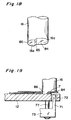
- a notch portion 16b for the drawing pin 32 to be inserted therein from the bottom is provided in the front portion of the lower end face 16a of the front floating rod 16 in order to properly insert the drawing pin 32 in the guide hole 8 of the lowermost ring portion 7.
- a tapered ring lead-in portion 16c is formed in the rear part of the lower end face 16a of the floating rod 16, and by this ring lead-in portion 16c, the ring portion 7 under draw can be led easily into between the lower end face 16a of the floating rod 16 and the heald receiving bottom surface 12a.
- a floating rod 16 without a notch portion 16b for drawing pin may be employed as the rear floating rod 16.
- the height ⁇ of the heald drawing opening 9 is determined so as to permit only the lowermost wire heald B hooked on the drawing pin 32 to pass. Therefore, even if the second and higher wire healdes B from the bottom are taken by friction together with horizontal drawing of the lowermost wire heald B while hooking the lowermost ring portion 7 on the drawing pin 32, the front ends of the ring portions 7 of the second and higher wire healdes B from the bottom will come to collide with the front wall of the front ring receiving portion 14, so that only the lowermost wire heald B can be drawn out of the heald drawing opening 9.
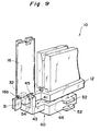
- the wire heald stocker 10 is provided with a heald front end separating portion 40 forming a heald pusher as a lift head in order to assure more certain drawing of the lowermost wire heald B.
- This heald front end separating portion 40 has push claws 41 located below the front floating rod 16, as shown in Fig. 10 and Fig. 11.
- the push claws 41 are formed in an L-shape and are paired right and left.
- Each push claw 41 comprises a claw portion 42 extending horizontally and arranged to engage with the lowermost ring portion 7 mounted on the front floating rod 16 and kept at that position, and a support portion 43 extending downward from the base end of the claw portion 42 in order to support this claw portion 42.
- a gap 44 is formed between the claw portions 42, 42 by spacing the tip portions (free end portions) of the right and left claw portions 42, 42 from each other, and this gap 44 is formed a little larger than the diameter of the rod portion 5 of wire heald B.
- a taper surface 42a inclined obliquely downward toward the tip is formed at the tip portion of each claw portion 42. Since upon ascent of the push claws 41 the tip end portions of the claw portions 42 come to be inserted into claw engaging recesses 45 formed in the lower end face 16a of the front floating rod 16, a taper face 45a to match with the taper face 42a of the claw portion 42 is formed in the top surface of each claw engaging recess 45 (see Fig. 8).
- claw receiving recesses 54 are formed in the front-end-side top surface of the base 12, as shown in Fig. 9.
- the rear floating rod 16 does not always have to be provided with the foregoing claw engaging recesses 45.
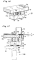
- the heald front end separating portion 40 has a base portion 46 for fixing each L-shaped push claw 41 in a standing state, and this base portion 46 is located below the base 12.
- a recessed portion 47 for a spring to be seated therein is formed in a top surface 46a of this base portion 46, and pin inserting holes 48 vertically piercing the base portion 46 are formed on either side of the recessed portion 47 (see Fig. 10).
- the top surface 46a of the base portion 46 and the bottom surface 12b of the base 12 are connected through a compression spring 50 seated in the recessed portion 47, and this compression spring 50 urges the base portion 46 in the direction to depart from the base 12.
- a driver 60 moves the base portion 46 up and down, as shown in Fig. 6.
- This driver 60 comprises an air cylinder 62 fixed to a support stage 61 for supporting the base 12 of the housing 11, a cylinder rod 63 arranged to reciprocate vertically in a predetermined stroke relative to this air cylinder 62 and prevented from rotating, and an actuator member 64 fixed to the tip end of this cylinder rod 63 and engaged with the tongues 52 of the base portion 46 at the tip end thereof. Accordingly, the base portion 46 can be moved up and down by a predetermined amount in accordance with the stroke amount of the cylinder rod 63. Since the actuator member 64 is given a play between the tongues 52 when the tip end of the actuator member 64 is inserted between the tongues 52, the stroke amount of the cylinder rod 63 is not equal to an ascent amount of the base portion 46.
- the drawing pin 32 is inserted into the notch portion 16b of the front floating rod 16 and at the same time as it, the ring portion 7 of the lowermost wire heald B is made to be magnetically attached to the magnetic head 31. Since the claw portions 42 of the push claws 41 are completely buried in the claw receiving recesses 54 at this time, they will never impede drawing of the ring portion 7. After that, the ring portion 7 is drawn a little by the drawing pin 32 so as to locate the rod portion 5 between the tips of the claw portions 42, thereby becoming ready for separation of wire heald B (see Fig. 11).
- the magnetic head 31 is moved horizontally until the drawing pin 32 comes to below a drop preventing plate 66 standing by in front of the heald drawing opening 9, whereby cooperation of the drop preventing plate 66 with the magnetic head 31 prevents the ring portion 7 of the lowermost wire heald B from slipping out.
- the air cylinder 62 is driven to move the actuator member 64 up as shown in Fig. 14 and Fig. 15, so that the tip of the actuator member 64 pushes the upper tongue 52 up to lift the base portion 46 by a predetermined amount against spring force of the compression spring 50. Since at this time the rod portion 5 of the lowermost wire heald B passes through the gap 44 between the claw portions 42 with ascent of the push claws 41, the lowermost wire heald B continuously keeps its position without being affected by ascent of the push claws 41. Then the tip portions of the claw portions 42 are inserted into the claw engaging recesses 45 of the front floating rod 16 to make the taper faces 42a and 45a fitting with each other and then to lift the front floating rod 16.
- the ring portions 7 of the stacked wire healdes B are also lifted utilizing the top faces 42b of the claw portions 42. This results in lifting the ring portions 7 in the stacked state as mounted on the floating rod 16 and kept at the position thereof together with the floating rod 16, whereby only the lowermost wire heald B can be separated from the other wire healdes B at the place of the front floating rod 16. Then cooperation of the drop preventing plate 66 with the magnetic head 31 achieves smooth drawing of the lowermost wire heald B with surely hooking the lowermost ring portion 7 on the drawing pin 32. After the lowermost wire heald B is drawn out completely, the air cylinder 62 is driven to move the actuator member 64 down, so as to return the base portion 46 to the position of Fig. 13 by the spring force of the compression spring 50, thus preparing for the next drawing operation.
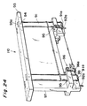
- the easy insertion of the wire healds into the stocker can be realized by using a cartridge 110 as shown in Fig. 24.
- a cruciate groove 98 is formed on a top of the floating rod 16 and a hole 92b is formed on a top of the ring receiving portion 14. They are utilized for positioning the cartridge to the stocker in the mounting operation.
- the cartridge 110 has a top support plate 93, storing rod 91 and a side support plate 97.
- the storing rod 91 is inserted into a hole 93a provided on the top support plate 93 and is supported by a pin 94.
- the side support plate 97 has a projection portion 99 and the projection portion 99 has a through hole 95 through which the storing rod 91 passes.
- An opening of the through hole 95 is slightly larger than a figure of the ring portion 7 of the wire heald in which the storing rods 91 fill and therefore, although the storing rod 91 can slightly moves in the through hole 95.
- the storing rod 91 is positioned so that a longitudinal direction of the storing rod 91 is kept to be along a vertical direction because the space between the storing rod 91 and an inner surface of the through hole 95 can be filled with the wire heald stored in the cartridge 110.
- the projection portion 99 has a spring hinge 96 for an arm 96a for supporting the wire heald stored in the cartridge 110 therein.
- the arm 96a is positioned as shown in a solid line of Fig. 24 normally and at the position, the arm 96a supports the wire heald therein.
- the arm 96a is moved to a position as shown in chain double-dashed lines of Fig. 24 by an actuator (not shown). At this position, the supporting of the arm 96a is released and therefore the stored wire healds fall down into the stocker 11.
- the storing rod 91 has a cruciate projection 91a in the bottom thereof and the cruciate projection 91a matches with the cruciate grooves 98 of the floating rod 16 in mounting of the cartridge to the stocker.
- the side supporting plate 97 has a pin 92a extending downwardly from the bottom thereof and the pin 92a is inserted into the hole 92b of the ring receiving portion 14 in the mounting of the cartridge 110 to the stocker 11.
- Fig. 25 shows the combination state under which the cartridge 110 is mounted on the stocker 11.
- the wire healds is inserted around the storing rod 91 from downside thereof, passing through the space 95 and stored therein.
- the arm 96a is positioned as shown in the solid lines of Fig. 24 to support the stored wire healds around the storing rod 91.
- the cartridge 110 is mounted on the stocker 11 so that the cartridge 110 is positioned on the stocker 11 by engaging the pin 92a with the holes 92b and engaging the cruciate projections 91a with the cruciate grooves 98.
- the arm 96a is moved by the actuator (not shown) to the position shown in the chain double-dashed lines of Fig. 24 so that the stored wire healds fall down into the stocker 11.
- the floating rod 16 is moved up by a predetermined distance and the predetermined distance should be smaller than the clearances ⁇ 1 and ⁇ 2 in Fig. 25.
- the stocker for wire healdes according to the present invention is by no means limited to the above-stated embodiment.
- the wire heald stocker 10 is provided with a heald rear end separating portion 70 forming a heald pusher as a lift head in order to assure more certain drawing of the lowermost wire heald B.
- This heald rear end separating portion 70 has a block-shaped lift member 71 located below the rear floating rod 16 and extending vertically. Below the rear floating rod 16, this lift member 71 is inserted into a rectangular aperture 72 formed in the base 12 from the bottom and stands on a base portion 73 located below the base 12.
- a recess 74 for a spring to be seated is formed in a top surface 73a of this base portion 73, and pin inserting holes 75 vertically piercing the base portion 73 are formed on either side of the recess 74. Also, the top surface 73a of the base portion 73 and the bottom surface 12b of the base 12 are connected through a compression spring 76 seated in the recess 74, and this compression spring 76 urges the base portion 73 in the direction to depart from the base 12.
- pins 77 are provided so as to project from the bottom surface 12a of the base 12, the pins 77 are inserted in the pin inserting holes 75 of the base portion 73, and stopper portions 77a comprised of snap rings or the like are provided at the lower ends of the pins 77, whereby the base portion 73 can be moved vertically in the extending direction of the pins 77 under elasticity of the spring 76.
- the base portion 73 is moved vertically by a driver 80 and this driver 80 is located immediately below the base portion 73.
- This driver 80 comprises an air cylinder 81 fixed through a bracket or the like to a portion of a support stage 61 for supporting the base 12 of the housing 11, and a cylinder rod 82 arranged to vertically reciprocate in a predetermined stroke relative to this air cylinder 81.
- the tip of this cylinder rod 82 is inserted from the bottom into an aperture 83 formed in the support stage 61 below the base portion 73, so as to face the bottom surface of the base portion 73.
- the cylinder rod 82 is made to project from the aperture 83, so that the tip of the cylinder rod 82 pushes the base portion 73 up, thereby lifting the base portion 73 and lift member 71. Then the cylinder rod 82 is moved down to bury the cylinder rod 82 in the aperture 83, whereby the base portion 73 and lift member 71 are moved down by the urging force of the spring 76.
- a ring lead-in portion 84 cut horizontally is formed at the rear part in the lower end face 16a of the rear floating rod 16, and this ring lead-in portion 84 has a cut depth P a little larger than the height H of one ring portion 7.
- a protrusion 86 projecting in the direction of the axis is formed at the front part in the lower end face 16a of the rear floating rod 16, and the lower end face 16a on the side of this protrusion 86 is connected through a taper face 85 with the lower end face 16a on the side of the ring lead-in portion 84.
- the cut depth P is made to be smaller than the height 2H of two ring portions 7.
- the drawing pin 32 is inserted into the notch portion 16b of the front floating rod 16 and at the same time as it, the front ring portion 7 of the lowermost wire heald B is made to be magnetically attached to the magnetic head 31. Since the claw portions 42 of the push claws 41 are buried completely in the claw receiving recesses 54 at this time, they will never impede drawing of the front ring portion 7. After that, the front ring portion 7 is drawn out a little by the drawing pin 32 (see Fig. 11). At this time, as shown in Fig. 19 and Fig.
- the rear end of the rear ring portion 7 in the lowermost is led into the ring lead-in portion 84 of the rear floating rod 16 as passing above the aperture 72 of the base 12, and thus, the ring portion 7 does not collide with the floating rod 16, thereby preventing the floating rod 16 from moving up. Further, the protrusion 86 of the rear floating rod 16 is located still in the lowermost ring portion 7.
- the air cylinder 81 is actuated to push the base portion 73 up by the tip of the cylinder rod 82, whereby the base portion 73 moves up while the lift member 71 also moves up as following it.
- the protrusion 86 inserted in the lowermost ring portion 7 is also lifted. Accordingly, the protrusion 86 is spaced away from the base 12, which completely releases engagement between the lowermost ring portion 7 and the floating rod 16.
- the drawing pin 32 is further advanced, so that the lowermost wire heald B is drawn out smoothly without collision between the rear floating rod 16 and the lowermost ring portion 7.
- the cylinder rod 82 is moved down to make the tip of the cylinder rod 82 buried in the aperture 83, thereby moving the base portion 73 and lift member 71 down by the urging force of the spring 76.
- the stocker for wire healdes according to the present invention can attain the following effects because it is arranged as described above.
- the wire healdes kept in a horizontal state are stacked vertically in the housing, in which the heald refilling aperture is provided at the top portion of the housing, and in which the heald drawing opening for discharging the lowermost of the stacked wire healdes in the horizontal direction is provided at the lower front end in the housing, stable stocking of wire healdes in the housing can be insured.
- the refilling operation can be performed from the top of the housing as utilizing the self-weight of healdes or the like, and thus the refilling operation of wire healdes becomes easy.
- the refilling operation can also be carried out as looking into the heald refilling aperture from the top.
- the wire heald can be drawn horizontally as maintained in the horizontal state, with hooking the guide hole of the lowermost wire heald on the pin or the like. Also, employment of the floating rods can prevent entanglement of wire healdes in the housing.
- provision of the heald front end separating portion in the stocker can decrease such a tendency that upon drawing of the lowermost wire heald the wire heald above it is also drawn together therewith by the drawing force of the lowermost wire heald, and can prevent the rear ring portion of the lowermost wire heald from vertically moving the front floating rod.
- the total weight of the stacked wire healdes and the weight of the floating rods is considerably greater than the drawing force of wire heald.
- the taper faces are formed at the tips of the claw portions, in which the claw engaging recesses for the tip portions of the claw portions to be inserted therein are formed in the lower end faces of the floating rod, and in which the taper faces arranged to match with the taper faces of the claw portions are formed in the top surface of the claw engaging recesses, even if the floating rod is set in such a state with a play as to move vertically and horizontally in the housing, engagement between the taper faces of the claw portions and the taper faces of the claw engaging recesses can assure certain lift of the floating rod as being positioned to the claw portions.
- the rod portion touches the claw portion upon ascent of the push claws because the position of the rod portion is shifted from the center of the lower end face of the floating rod to the edge, the rod portion can be moved along the taper face of the claw portion, whereby the rod portion can be surely introduced into the gap between the claw portions.
- the heald rear end separating portion in the stocker can decrease such a tendency that upon drawing of wire heald the drawing force of the lowermost wire heald pulls the wire heald above it together therewith.
- the ring lead-in portion cut horizontally is provided the lower end face of the floating rod, the floating rod can be kept from colliding with the lowermost ring portion upon drawing of the lowermost wire heald, which can suppress abrasion and deformation of the floating rod and wire heald.
Landscapes
- Engineering & Computer Science (AREA)
- Textile Engineering (AREA)
- Auxiliary Weaving Apparatuses, Weavers' Tools, And Shuttles (AREA)
- Coiling Of Filamentary Materials In General (AREA)
Applications Claiming Priority (2)
| Application Number | Priority Date | Filing Date | Title |
|---|---|---|---|
| JP4297/96 | 1996-01-12 | ||
| JP8004297A JPH09195149A (ja) | 1996-01-12 | 1996-01-12 | ワイヤヘルド用ストッカ |
Publications (1)
| Publication Number | Publication Date |
|---|---|
| EP0784112A1 true EP0784112A1 (fr) | 1997-07-16 |
Family
ID=11580590
Family Applications (1)
| Application Number | Title | Priority Date | Filing Date |
|---|---|---|---|
| EP97100365A Withdrawn EP0784112A1 (fr) | 1996-01-12 | 1997-01-10 | Magasin pour lisses en fil métallique |
Country Status (4)
| Country | Link |
|---|---|
| US (1) | US5829109A (fr) |
| EP (1) | EP0784112A1 (fr) |
| JP (1) | JPH09195149A (fr) |
| KR (1) | KR970059336A (fr) |
Citations (2)
| Publication number | Priority date | Publication date | Assignee | Title |
|---|---|---|---|---|
| FR544585A (fr) * | 1920-12-16 | 1922-09-25 | Machine à introduire les lisses du métier à tisser | |
| EP0298696A1 (fr) * | 1987-07-10 | 1989-01-11 | TEIJIN SEIKI CO. Ltd. | Dispositif de transfert pour lices à tisser |
Family Cites Families (4)
| Publication number | Priority date | Publication date | Assignee | Title |
|---|---|---|---|---|
| JPH0449189A (ja) * | 1990-06-19 | 1992-02-18 | Toshiba Corp | エレベータのコンペンセータ装置 |
| CH682576A5 (de) * | 1990-08-20 | 1993-10-15 | Zellweger Uster Ag | Vorrichtung zum Vereinzeln von Lamellen in Kettfadeneinziehmaschinen. |
| CH687027A5 (de) * | 1992-03-11 | 1996-08-30 | Staeubli Ag Zweigwerk Sargans | Lamellensepariervorrichtung fuer Kettfadeneinziehmaschinen. |
| CH687881A5 (de) * | 1993-09-13 | 1997-03-14 | Staeubli Ag Zweigwerk Sargans | Litzensepariervorrichtung fuer Kettfadeneinziehmaschinen. |
-
1996
- 1996-01-12 JP JP8004297A patent/JPH09195149A/ja active Pending
-
1997
- 1997-01-10 KR KR1019970000399A patent/KR970059336A/ko not_active Withdrawn
- 1997-01-10 EP EP97100365A patent/EP0784112A1/fr not_active Withdrawn
- 1997-01-10 US US08/782,890 patent/US5829109A/en not_active Expired - Fee Related
Patent Citations (2)
| Publication number | Priority date | Publication date | Assignee | Title |
|---|---|---|---|---|
| FR544585A (fr) * | 1920-12-16 | 1922-09-25 | Machine à introduire les lisses du métier à tisser | |
| EP0298696A1 (fr) * | 1987-07-10 | 1989-01-11 | TEIJIN SEIKI CO. Ltd. | Dispositif de transfert pour lices à tisser |
Also Published As
| Publication number | Publication date |
|---|---|
| JPH09195149A (ja) | 1997-07-29 |
| US5829109A (en) | 1998-11-03 |
| KR970059336A (ko) | 1997-08-12 |
Similar Documents
| Publication | Publication Date | Title |
|---|---|---|
| US6499642B1 (en) | Magazine mechanism for nailing machine | |
| US5829109A (en) | Stocker for wire healds | |
| EP0780501B1 (fr) | Magasin pour lisses plates | |
| US5839606A (en) | Method/apparatus for separating wire healds | |
| US5090607A (en) | Feed belt for rivets | |
| CN115108210B (zh) | 进仓装置、入库设备以及带式仓储系统 | |
| JPH05507327A (ja) | 織物機械用の杼口形成装置 | |
| US5826315A (en) | Flat heald/dropper-drawing/separating method and apparatus | |
| US5060784A (en) | Torsion spring conveying and separating system | |
| JPS58186639A (ja) | 織機のよこ糸引張り装置 | |
| JPH09217252A (ja) | ワイヤヘルド分離方法及びワイヤヘルド分離機構 | |
| EP0777005A2 (fr) | Procédé et dispositif pour passer des fils de chaîne | |
| JPH09296339A (ja) | ワイヤヘルドの引出し方法及び引出し装置 | |
| JPH09296337A (ja) | ワイヤヘルドの引出し方法及び引出し装置 | |
| JPH09296341A (ja) | ワイヤヘルドの引出し方法及び引出し装置 | |
| JPH09291443A (ja) | ワイヤヘルド分離方法及びワイヤヘルド分離装置 | |
| CN219709011U (zh) | 一种装卸平台 | |
| JPH09296338A (ja) | フラットヘルドの引出し方法及び引出し装置 | |
| JP2789324B2 (ja) | ジャカード機の経糸選択制御装置 | |
| JPH09250058A (ja) | ドロッパ用ストッカ | |
| CN220318055U (zh) | 一种加弹机筒子纱支架机构 | |
| JPH09296342A (ja) | ドロッパ分離方法及びドロッパ分離機構 | |
| US5765356A (en) | Spinning machine tube transport and removal system | |
| JPH0859089A (ja) | ボビン搬送用トレイ | |
| KR20000075412A (ko) | 자수기의 셔틀 교환 방법 및 장치 |
Legal Events
| Date | Code | Title | Description |
|---|---|---|---|
| PUAI | Public reference made under article 153(3) epc to a published international application that has entered the european phase |
Free format text: ORIGINAL CODE: 0009012 |
|
| AK | Designated contracting states |
Kind code of ref document: A1 Designated state(s): CH DE FR IT LI |
|
| STAA | Information on the status of an ep patent application or granted ep patent |
Free format text: STATUS: THE APPLICATION IS DEEMED TO BE WITHDRAWN |
|
| 18D | Application deemed to be withdrawn |
Effective date: 19980117 |