EP0796665A2 - Système et procédé d'alimentation en peinture d'une installation de revetment - Google Patents
Système et procédé d'alimentation en peinture d'une installation de revetment Download PDFInfo
- Publication number
- EP0796665A2 EP0796665A2 EP97104631A EP97104631A EP0796665A2 EP 0796665 A2 EP0796665 A2 EP 0796665A2 EP 97104631 A EP97104631 A EP 97104631A EP 97104631 A EP97104631 A EP 97104631A EP 0796665 A2 EP0796665 A2 EP 0796665A2
- Authority
- EP
- European Patent Office
- Prior art keywords
- containers
- container
- coating
- transport device
- filling
- Prior art date
- Legal status (The legal status is an assumption and is not a legal conclusion. Google has not performed a legal analysis and makes no representation as to the accuracy of the status listed.)
- Granted
Links
Images


Classifications
-
- B—PERFORMING OPERATIONS; TRANSPORTING
- B05—SPRAYING OR ATOMISING IN GENERAL; APPLYING FLUENT MATERIALS TO SURFACES, IN GENERAL
- B05B—SPRAYING APPARATUS; ATOMISING APPARATUS; NOZZLES
- B05B5/00—Electrostatic spraying apparatus; Spraying apparatus with means for charging the spray electrically; Apparatus for spraying liquids or other fluent materials by other electric means
- B05B5/16—Arrangements for supplying liquids or other fluent material
- B05B5/1608—Arrangements for supplying liquids or other fluent material the liquid or other fluent material being electrically conductive
- B05B5/1616—Arrangements for supplying liquids or other fluent material the liquid or other fluent material being electrically conductive and the arrangement comprising means for insulating a grounded material source from high voltage applied to the material
- B05B5/1625—Arrangements for supplying liquids or other fluent material the liquid or other fluent material being electrically conductive and the arrangement comprising means for insulating a grounded material source from high voltage applied to the material the insulating means comprising an intermediate container alternately connected to the grounded material source for filling, and then disconnected and electrically insulated therefrom
-
- B—PERFORMING OPERATIONS; TRANSPORTING
- B05—SPRAYING OR ATOMISING IN GENERAL; APPLYING FLUENT MATERIALS TO SURFACES, IN GENERAL
- B05B—SPRAYING APPARATUS; ATOMISING APPARATUS; NOZZLES
- B05B12/00—Arrangements for controlling delivery; Arrangements for controlling the spray area
- B05B12/14—Arrangements for controlling delivery; Arrangements for controlling the spray area for supplying a selected one of a plurality of liquids or other fluent materials or several in selected proportions to a spray apparatus, e.g. to a single spray outlet
- B05B12/1463—Arrangements for controlling delivery; Arrangements for controlling the spray area for supplying a selected one of a plurality of liquids or other fluent materials or several in selected proportions to a spray apparatus, e.g. to a single spray outlet separate containers for different materials to be sprayed being moved from a first location, e.g. a filling station, where they are fluidically disconnected from the spraying apparatus, to a second location, generally close to the spraying apparatus, where they are fluidically connected to the latter
-
- B—PERFORMING OPERATIONS; TRANSPORTING
- B05—SPRAYING OR ATOMISING IN GENERAL; APPLYING FLUENT MATERIALS TO SURFACES, IN GENERAL
- B05B—SPRAYING APPARATUS; ATOMISING APPARATUS; NOZZLES
- B05B13/00—Machines or plants for applying liquids or other fluent materials to surfaces of objects or other work by spraying, not covered by groups B05B1/00 - B05B11/00
- B05B13/02—Means for supporting work; Arrangement or mounting of spray heads; Adaptation or arrangement of means for feeding work
- B05B13/04—Means for supporting work; Arrangement or mounting of spray heads; Adaptation or arrangement of means for feeding work the spray heads being moved during spraying operation
- B05B13/0431—Means for supporting work; Arrangement or mounting of spray heads; Adaptation or arrangement of means for feeding work the spray heads being moved during spraying operation with spray heads moved by robots or articulated arms, e.g. for applying liquid or other fluent material to three-dimensional [3D] surfaces
- B05B13/0433—Means for supporting work; Arrangement or mounting of spray heads; Adaptation or arrangement of means for feeding work the spray heads being moved during spraying operation with spray heads moved by robots or articulated arms, e.g. for applying liquid or other fluent material to three-dimensional [3D] surfaces the work being vehicle components, e.g. vehicle bodies
Definitions
- the invention relates to a method and a system for supplying paint to a coating system for the serial coating of workpieces, in particular vehicle bodies.
- interchangeable containers are filled at tapping points located in the spray booth in the movement area of the robot and connected to paint supply lines, from where the painting robot fetches them itself as required .
- the interchangeable containers can be coupled to one of the numerous lines at different points, while in another embodiment only two containers are provided, one of which is mounted on the robot, while the other is filled on a color changer connected to the connecting lines.
- Such a system avoids long hoses between the spray device and the supply lines and enables electrostatic coating with electrically conductive coating material without problems of a conductive connection between the spray device and the supply lines.
- the known system requires a relatively high level of control if each paint supply line is assigned its own interchangeable container, since the robot has to move to a different tap each time the color is changed. In addition, the robot must wait for the container to be filled when it starts up at the tap. If, on the other hand, there are only two containers to be alternately filled and used, they have to be rinsed each time the color is changed, which leads to a loss of time for the coating operation and to the loss of the material remaining in the container for reserve reasons. In any case, the robot must carry out complex controlled movements to couple the containers to the tapping points.
- the aim of the invention is a method or system suitable for serial coating, in particular of motor vehicle bodies, with the greatest possible flexibility with regard to the paints, spraying devices and coating machines to be used, which, when filling the exchangeable containers, enables low color change losses and largely delay-free coating operation, and preferably also in this case gets along with low tax expenditure, especially for the control of necessary movements.
- the containers can be filled with material of the same color and are only rinsed if it is determined by a preferably automatic control and monitoring system that the container is not used for coating for a predetermined period of time or is incompletely emptied during coating or has not been refilled after emptying, which occurs only rarely, or if a container has to be filled with a different color, because exceptionally there is no container with a suitable color available for an upcoming coating process. As a result, the color loss caused by regular rinsing is avoided.
- the respective fill quantities are also not critical in this regard. Per se It may be expedient to fill the container only with a predetermined amount of material that is required for a predetermined coating process, for example for coating a body, but a sufficient reserve amount is normally required. Excess paint can remain in the container and will be sprayed the next time the container is used.
- the system also works with the least possible loss of time, which, if the containers are appropriately pre-positioned on the transport device, is limited to the time required for coupling the containers to the spraying device and decoupling them can be. These losses of time can also be avoided for the coating if at least two alternating coating devices are provided during operation.
- the system is suitable for the paint supply of largely any coating systems, e.g. for electrostatic systems for conventional paints or electrically conductive water-based paints, or also for air atomizers, and not just for robots like the known systems mentioned above, but for any mechanical or manual coating devices.
- electrically conductive coating materials the required potential separation between the atomizers at high voltage potential and the supply or supply systems at earth potential results due to the container transport. Only simple movements need to be controlled, which in turn can significantly reduce the control effort for robots and other coating devices.
- the arms carrying the spraying device can be pivoted into a vertical position on the side of the machine facing the transport device for taking over the containers from or back to the transport device, which is also easy to control.
- the coating machine for taking over and transferring the containers is moved to the transfer point parallel to the direction of conveyance of the workpieces to be coated.
- the container is preferably inserted through an opening of the arm in its interior, where it can be very easily coupled on the one hand to control valves of the flushing device and on the other hand to an electromechanical drive for the metered emptying of the container, as in DE patent application 196 10 588.9 dated March 18. 1996 is described.
- the invention enables coating with practically any color tones without any problems, since not only are the colors available in the supply lines which have been customary hitherto available, but also all possible mixtures of these and / or other colors.
- the mixing can take place in the container by filling in different colors or even before filling the container in question, automatically by combining at least two different colors, for example from the connected supply lines or manually.
- any color can be made available in a fully automatic manner, which is carried out by an electronic control system in accordance with the respective requirements.
- the transport device can also be equipped with containers filled externally without connection to the supply lines of the filling point of the system described here.
- a device is to be provided which automatically couples the container to a device fed by at least one supply line.
- the arrangement of the colors on the transport device can be carried out at any position depending on the expediency, since the automatic devices for feeding and removing or filling the containers provided at the transfer point and at the filling point have free access to all positions on the transport device.
- the filling point or at least the transfer point could be located within the spray booth in which the coating is usually carried out.
- the spray booth should contain as few components of the overall system as possible, especially in the actual spray area, among other things because of the risk of contamination from the sprayed coating material and because of impaired freedom of movement of the coating machines.
- the transport device should therefore preferably be located completely outside the spray booth, for example in the maintenance area of the system, and be separated from the spray device by a wall, the containers being fed to the spray device through an opening in the wall and brought back to the transport device will.
- the transport device of the system described here can be of any type per se, for example a belt conveyor or a chain conveyor.
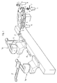
- a magazine 1 which can be rotated in one or both directions, is used as the transport device and can be provided with devices for receiving and holding cartridge-like containers 2 in a plurality of uniformly distributed positions, as is the case with tool magazines is known and common in connection with tool changing devices.
- the magazine expediently serves for the simultaneous storage of a multiplicity of containers which is at least equal to the number or preferably equal to twice the number of selectable colors.
- the arrow 4 indicates a filling point in which the containers 2 inserted into the magazine 1 are automatically filled with the different colors desired in each case. You can stay in the magazine when filling, if a correspondingly movable filling device on the container to be filled is coupled, as assumed in the case shown. In other cases, the containers for filling can be removed from the magazine by a suitable device and then also automatically coupled to the filling device.
- the filling device assumed to be movable here contains, as the most important component, a color changer 6 or at least one movable device connected to a color changer, the color changer in turn being connected to a multiplicity of ring lines, generally designated 7, in which available coating materials of different colors circulate.
- individual containers for example with individually mixed special colors, can be inserted manually at the filling point.
- a filled container 2 ' is gripped by a linear movement device 12, which for example has a piston-cylinder drive unit and can be mounted on the magazine 1, removed from the magazine and one along the linear path 13 shown supplied with the spraying device (not shown) provided coating machine.
- a linear movement device 12 which for example has a piston-cylinder drive unit and can be mounted on the magazine 1, removed from the magazine and one along the linear path 13 shown supplied with the spraying device (not shown) provided coating machine.
- the coating machine is a painting robot 14, which can be moved parallel to the conveying direction of the workpieces (not shown) fed to it with a conventional conveyor, as the arrow 15 shows.
- the robot 14 is moved back and forth along this direction between a working position 14a and a container change position 14b, in which the full container 2 'is transferred to it and an empty container can be removed.
- the container 2 ' is preferably to be inserted through an opening into the interior of the arm 16 of the robot 14 and to be coupled there to a control valve construction of the spray device.
- the robot arm 16 is pivoted into the vertical position shown, in which the aforementioned opening of the arm 16 faces the transfer device 12 of the magazine 1, that is to say lies in a vertical plane intersecting the horizontal path 13 approximately at right angles.
- the necessary pivoting movement of the robot arm 16 is made possible by the illustrated one-sided mounting of this arm on the robot.
- the robot In order to get into the container change position 14b and to get a filled container and to deliver an empty container, the robot only has to carry out a few uncomplicated movements.
- the linear movement device 12 which is only shown schematically, can be designed in such a way that it is able to hold at least two containers at the same time and to hold the full container ready while it is removing the empty container. 2 schematically shows that the device 12 also executes a transverse movement perpendicular to the horizontal path 13, which can also be a rotational movement. After inserting the new container 2 ', the robot returns to its working position 14a.
- the same device 12 which removes the containers 2 from the transport device and feeds them to the spraying device, also brings the containers back to the transport device.
- two devices are provided at the transfer point, one of which feeds the containers to the spraying device, while the other device brings another container back to the transport device.
- the robot 14 works in the usual way within a spray booth.
- the transport device here the magazine 1, completely outside the cabin and separating it from the robot by a wall (not shown).
- the containers 2 ' can be easily fed to the spraying device through an opening in this wall and returned to the magazine 1.
- a second painting robot can work on the opposite side of the bodies to be coated, which robot receives its exchangeable containers from a further supply system of the type described here provided there.
- at least two parallel magazines or transport devices of the type described can also be provided on the same cabin side.
- the containers 2 are filled at the filling point 4 and how the colors required during operation are provided in the conveying device.
- a device similar to the linear movement device 12 described or another handling device could be used;
- the containers according to FIG. 1 remain in the magazine 1 during filling, as has already been mentioned, while a movable control valve connected to the color changer 6, for example from below, is in one End wall of the container 2 provided valve openings is coupled, as shown in more detail in Fig. 3.
- the cartridges or containers 2 are designed as cylindrical dosing containers which contain a piston 20 which can be displaced in the container and whose position in the container defines the volume to be filled and thus the amount of lacquer to be sprayed.
- the position of the piston 20 can be adjusted via a piston rod 23 before the filling of an electric motor 22, for example a stepper motor, which in turn is controlled by the electrical control system of the filling station in accordance with the amount of paint required in each case.
- the container is emptied in that a mechanical drive mechanism located in the robot 14 moves the piston 20 against the bottom of the container.
- the container valves 25 and 26 provided for filling and emptying are located in the opposite end.
- the valve 25 serves for filling in the filling station and for removing the coating material during coating, that is to say coupled to the spraying device in the robot 14.
- the valve 26 serves, if necessary, for emptying the container 2 in the filling station, in which the containers can also be rinsed.
- a handle 21 for the above-mentioned handling device for inserting the container into the robot and for returning it into the magazine 1 can be attached to the side wall of the container 2.
- At the front end of the container there are centering means for aligning the valves 25, 26 with those of the color changer.
- the color changer 6 is coupled to the container 2 by the control valve unit 28 connected to it.
- a line 30 is connected to the container valve 25, which in turn is in a conventional manner in the color changer 6 via corresponding Valves F1 to Fn have access to a number of ring lines or other supply lines for different colors.
- the color changer also contains valves V for a flushing agent or solvent and further valves PL for compressed air used for emptying and flushing the container 2.
- Return valves are designated by RF, which are connected to a line 33, on the one hand, connectable to the drain valve 26 of the container 2 and, on the other hand, leading into a collecting container 32.
- the containers 2 can be provided with preferably machine-readable characteristic data, for example about the color, quantity of paint, container number, container size, marking of the coating process to be carried out, etc., so that optimum monitoring and control of the operation is always possible.
- the container can be assigned to a specific workpiece to be coated by the electronic control system.
- the identification data on the container can be fixed or overwritable.
- FIG. A belt or chain conveyor 40 which rotates around horizontal axes and in which the containers 42 are held horizontally by a chain or a belt 41 serves as the transport device here.
- a color changer 46 connected via lines 47 to ring lines or preferably a movable flushable filling coupling 51 fed by it is coupled to the containers 42 to be filled by an automatically controlled displacement device.
- further supply lines 48 are connected to the color changer 46, at least some of which lead to pressure vessels 49 or other storage containers for special colors or other coating materials which cannot be removed from the lines 47. For example, different colors could be mixed in the kettles 49.
- Lines 47, 48 each include control air lines for valve actuation.
- a linear movement device 50 or other positioning device for example driven by a piston-cylinder unit, is provided for removing and reinserting the containers 42.
- the conveyor 40 is positioned by a drive 52 controlled by the electronic control system in such a way that the required containers can be removed or filled at the transfer and filling points at the right time.
- a flow meter 54 can expediently be arranged on the line leading from the color changer 46 into the container 42. Dosed filling can thus be monitored or the filling quantity can also be controlled by appropriate control of the existing valves. The piston control during filling described in the embodiment according to FIG. 3 is therefore not absolutely necessary.
- the spatial distance of the filling point from the transfer point or from the spray device is at least as large as the distance required for electrical insulation. Regardless of the type of spraying devices, the filling point should be outside the spray booth for the reasons already mentioned.
- FIG. 5 schematically shows a paint supply system according to another exemplary embodiment of the invention.
- the coating device 50 is located at the transfer point 10, to which the full containers 2 are transported from the filling point 4 in non-stationary magazines 52.
- the transport of these magazines 52, which serve as movable transport devices, from the filling point 4 to the transfer point 10 can be carried out, depending on the expediency, with various means or conveyors 54, for example with a rail-bound conveyor or a conveyor controlled by an induction loop or a chain conveyor etc. or in special cases also manually, if applicable, on the wagon shown.
- the containers 2 or, in the example shown, their magazines 52 can either be fed directly from the filling point 4 from the individual coating devices, or instead the magazines can approach the various coating devices in sequence, where a full container in each case removed and / or an empty container from the coating device is returned to the magazine.
- a mixing bench 55 can also be provided at the filling point, from which various coating materials of different colors get into the containers that previously or in the containers achieve a desired one Color can be mixed.
- the containers can be rinsed at the filling point.
- the containers can be subjected to a quantity test and a pressure test, they can be shaken to move their contents, and they can be automatically positioned with respect to the magazines 52 and with respect to existing filling devices .
- Both the filling and, if necessary, the emptying and rinsing of the containers at the filling point 4 as well as the loading of the conveyors 54 symbolized by a trolley can be carried out manually or automatically.
- the containers 2 are provided with machine-readable or possibly also visually readable characteristic data for identifying their contents, including the type of paint, filling date, etc. If a plurality of magazines 54 are used, these too are provided with their own identifications or identification data for identifying containers contained in them.
- the magazines 52 with the containers 2 to be filled can be taken from a magazine supply in a store 56 and from there e.g. can be brought into the positions required for filling, emptying or flushing by means of an automatic handling device 58 or another conveying device or also manually.
- the memory 56 can be located directly at the filling point 4 in a paint mixing room or at a remote location.
- the memory can contain magazines 52 and / or individual containers 2. These can be fully or partially full, empty, used or flushed.
- a store for magazines with already filled containers could also be provided.
- the containers 2 removed from the coating device at the transfer point 10 after use can first be transported into the storage 56 before they are used further at the filling point.
- the magazines 2 used for the transport into the store can be transported on similar conveyors 54 'as on the way to the coating device 50.
- the entire operating sequence is expediently monitored and controlled by a computing and control system symbolized at 60.
- This system provides, in particular, with the help of the mentioned characteristics, among others. to ensure that all existing coating devices are supplied with the coating material required as quickly as possible and with the least possible material loss.
- the containers used according to the invention have numerous advantageous properties per se. They are suitable for metering, can be airtight and designed as pressure vessels, offer protection against aging of the coating material, serve as transport containers, ink storage and for decoupling the coating devices from ring lines or other ink supply systems, are location-independent, flushable and reusable and can be easily identified will. Furthermore, they are easy to grip and easy to center and lock when coupling.
Landscapes
- Engineering & Computer Science (AREA)
- Robotics (AREA)
- Spray Control Apparatus (AREA)
- Electrostatic Spraying Apparatus (AREA)
- Nozzles (AREA)
Applications Claiming Priority (2)
| Application Number | Priority Date | Filing Date | Title |
|---|---|---|---|
| DE19610589 | 1996-03-18 | ||
| DE19610589A DE19610589A1 (de) | 1996-03-18 | 1996-03-18 | Verfahren und System zur Farbversorgung einer Beschichtungsanlage |
Publications (3)
| Publication Number | Publication Date |
|---|---|
| EP0796665A2 true EP0796665A2 (fr) | 1997-09-24 |
| EP0796665A3 EP0796665A3 (fr) | 1998-04-08 |
| EP0796665B1 EP0796665B1 (fr) | 2000-07-12 |
Family
ID=7788630
Family Applications (1)
| Application Number | Title | Priority Date | Filing Date |
|---|---|---|---|
| EP97104631A Expired - Lifetime EP0796665B1 (fr) | 1996-03-18 | 1997-03-18 | Système et procédé d'alimentation en peinture d'une installation de revêtement |
Country Status (3)
| Country | Link |
|---|---|
| EP (1) | EP0796665B1 (fr) |
| DE (2) | DE19610589A1 (fr) |
| ES (1) | ES2148864T3 (fr) |
Cited By (20)
| Publication number | Priority date | Publication date | Assignee | Title |
|---|---|---|---|---|
| WO1998006503A1 (fr) * | 1996-08-10 | 1998-02-19 | Herberts Gesellschaft mit beschränkter Haftung | Procede et dispositif de mise en peinture |
| WO1999052644A1 (fr) * | 1998-04-15 | 1999-10-21 | Sames S.A. | Procede et installation de projection de produit de revetement au moyen d'un automate equipe d'un reservoir |
| DE19838805A1 (de) * | 1998-08-26 | 2000-03-09 | Duerr Systems Gmbh | Verfahren und System zur Farbversorgung einer Beschichtungsanlage |
| FR2794384A1 (fr) * | 1999-06-04 | 2000-12-08 | Sames Sa | Procede d'alimentation de produits de revetement pour l'application manuelle de tels produits sur des objets deplaces sur un convoyeur, installation et equipement correspondants |
| WO2001014067A1 (fr) * | 1999-08-26 | 2001-03-01 | Abb Patent Gmbh | Procede et dispositif servant a l'acheminement de peinture electriquement conductrice |
| WO2002032585A1 (fr) | 2000-10-19 | 2002-04-25 | Sames Technologies | Dispositif et procede d'alimentation de projecteurs et installation de projection equipee d'un tel dispositif |
| WO2002032586A1 (fr) | 2000-10-19 | 2002-04-25 | Sames Technologies | Dispositif et procede d'alimentation de projecteurs et installation de projection equipee d'un tel dispositif |
| EP1252935A2 (fr) | 2001-04-25 | 2002-10-30 | Dürr Systems GmbH | Procédé de commande du fonctionnement d'une installation de revêtement |
| EP1010469A3 (fr) * | 1998-12-17 | 2003-02-05 | Dürr Systems GmbH | Système et procédé d'alimentation en peinture d'une installation de revêtement électrostatique |
| EP1293260A2 (fr) | 2001-09-13 | 2003-03-19 | Dürr Systems GmbH | Procédé de revêtement de pièces en séries |
| EP1634651A1 (fr) | 2004-09-13 | 2006-03-15 | Dürr Systems GmbH | Méthode et dispositif de revêtement de pièces en série et pulvérisateur rotatif |
| US7908994B2 (en) | 2005-10-21 | 2011-03-22 | Duerr Systems, Inc. | Automatically steered coating machine also a container for the coating material |
| DE102004059870B4 (de) * | 2004-12-13 | 2011-06-22 | EISENMANN Anlagenbau GmbH & Co. KG, 71032 | Verfahren und Anlage zur Beschichtung von Gegenständen |
| US8201585B2 (en) | 2005-06-09 | 2012-06-19 | Trinity Industrial Corporation | Method and apparatus for filling coating material |
| US8418647B2 (en) | 2005-10-21 | 2013-04-16 | Dürr Systems Inc. | Procedure and piston type metering devices for the metered material supply for a coating device |
| CN104998786A (zh) * | 2014-12-31 | 2015-10-28 | 陈煜达 | 大型工件喷涂系统 |
| CN110180709A (zh) * | 2019-05-22 | 2019-08-30 | 昆山缘瑞塑胶科技有限公司 | 一种口红管外壳喷涂生产线 |
| CN114515661A (zh) * | 2021-12-28 | 2022-05-20 | 刘晓玲 | 一种用于浸渍非连续纤维的液体树脂喷涂装置 |
| WO2023020819A1 (fr) | 2021-08-19 | 2023-02-23 | Dürr Systems Ag | Procédé pour faire fonctionner un pulvérisateur et installation de peinture correspondante |
| CN119212219A (zh) * | 2024-09-09 | 2024-12-27 | 奥士康科技股份有限公司 | 一种监控任意层间对准度的电路板印刷方法 |
Families Citing this family (5)
| Publication number | Priority date | Publication date | Assignee | Title |
|---|---|---|---|---|
| DE19830029A1 (de) * | 1998-07-04 | 2000-01-05 | Audi Ag | Anlage zum Beschichten von Gegenständen, insbesondere von Fahrzeug-Karosserien |
| DE19940542A1 (de) * | 1999-08-26 | 2001-03-01 | Abb Patent Gmbh | Verfahren und Anordnung zum Transport von elektrisch leitfähigem Lack |
| DE102004053819A1 (de) * | 2004-11-04 | 2006-05-11 | Tecnobless Gmbh | Sprühanlage mit auswechselbaren Sprühmittelbehältern |
| JP4917354B2 (ja) * | 2006-05-30 | 2012-04-18 | トリニティ工業株式会社 | 塗装システム |
| MX2019014165A (es) | 2018-11-28 | 2020-08-03 | Prec Valve And Automation Inc | Robot multiple de cuarto eje. |
Family Cites Families (29)
| Publication number | Priority date | Publication date | Assignee | Title |
|---|---|---|---|---|
| DE1208692B (de) * | 1962-12-19 | 1966-01-05 | Standard Elektrik Lorenz Ag | Speichereinrichtung fuer Rohrpostbuechsen, insbesondere Grossrohrpostbehaelter |
| GB1232893A (fr) * | 1969-05-02 | 1971-05-19 | ||
| BE755696A (fr) * | 1969-09-03 | 1971-03-03 | Carrier Engineering Co Ltd | Appareil destine a commande le fonctionnement d'un pistolet de pulverisation |
| GB1559796A (en) * | 1975-09-13 | 1980-01-30 | Molins Ltd | Apparatus for handling packets |
| DE2819302C3 (de) * | 1978-05-02 | 1988-07-28 | Ransburg Gmbh, 6056 Heusenstamm | Lackmengen-Steuersystem |
| IL67722A0 (en) * | 1982-02-05 | 1983-05-15 | Plessey Overseas | Container with memory |
| AU548810B2 (en) * | 1982-04-27 | 1986-01-02 | Daiwa Can Company Limited | Method and apparatus for handling metal containers |
| DE3228161C1 (de) * | 1982-07-28 | 1984-01-19 | Karl 7298 Loßburg Hehl | Beschickungseinrichtung zum Zufuehren von Kunststoffgranulat in eine Spritzgiesseinheit |
| JPS59186807A (ja) * | 1983-04-06 | 1984-10-23 | Fuji Photo Film Co Ltd | マイクロフイルムカ−トリツジの収納・取出機構 |
| US4588341A (en) * | 1983-07-08 | 1986-05-13 | Motoda Denshi Kogyo Kabushiki Kaisha | Article delivery apparatus |
| DE3340614C1 (de) * | 1983-11-10 | 1985-02-21 | Daimler-Benz Ag, 7000 Stuttgart | Einrichtung zum Lackieren von Serienteilen mit wechselnder Farbe |
| JPS60122073A (ja) * | 1983-12-05 | 1985-06-29 | Tokico Ltd | 塗装用ロボットの色替装置 |
| DE3416169A1 (de) * | 1984-05-02 | 1985-11-07 | W. Fechter GmbH Ingenieurunternehmen, 8500 Nürnberg | Vorrichtung zum aufbringen von beschichtungsstoffen und/oder farbueberzuegen |
| FR2609252B1 (fr) * | 1987-01-02 | 1989-04-21 | Sames Sa | Installation de projection de produit de revetement tel que par exemple une peinture et notamment installation de projection electrostatique de peinture a base d'eau |
| US4932589A (en) * | 1988-09-30 | 1990-06-12 | Binks Manufacturing Company | Method of and apparatus for electrical isolation of electrostatic sprayers |
| DE8906341U1 (de) * | 1989-05-23 | 1989-08-24 | Sata - Farbspritztechnik GmbH & Co, 7140 Ludwigsburg | Lackierroboter |
| DE4013942A1 (de) * | 1990-04-30 | 1991-10-31 | Behr Industrieanlagen | Anlage zum serienweisen beschichten von werkstuecken mit leitfaehigem beschichtungsmaterial |
| DE4013941A1 (de) * | 1990-04-30 | 1991-10-31 | Behr Industrieanlagen | Anlage zum serienweisen beschichten von werkstuecken mit leitfaehigem beschichtungsmaterial |
| DE4117613A1 (de) * | 1991-05-29 | 1992-12-03 | Ransburg Gmbh | Spruehbeschichtungsvorrichtung |
| FR2677611A1 (fr) * | 1991-06-11 | 1992-12-18 | Sames Sa | Reservoir a capacite ajustable, pour produit liquide. |
| US5238029A (en) * | 1991-10-04 | 1993-08-24 | Fanuc Robotics North America, Inc. | Method and system for fluid transfer and non-contact sensor for use therein |
| DE4208500C2 (de) * | 1992-03-17 | 1994-05-11 | Kleinmichel Klaus Gmbh | Spritzvorrichtung zum Aufbringen eines flüssigen Mediums wie Farbe |
| FR2695327B1 (fr) * | 1992-09-09 | 1995-07-07 | Sames Sa | Dispositif de projection électrostatique de produit de revêtement électriquement conducteur, muni d'un réservoir isolé adapté à contenir un tel produit. |
| DE4339302C2 (de) * | 1993-11-18 | 1999-12-30 | Abb Patent Gmbh | Farbwechselblock mit Leckageindikatoren |
| DE4342128A1 (de) * | 1993-12-10 | 1995-06-14 | Abb Patent Gmbh | Farbauftragvorrichtung |
| DE4423643A1 (de) * | 1994-07-06 | 1996-01-11 | Ind Lackieranlagen Schmidt Gmb | Einrichtung zum Lackieren von Gegenständen mit verschiedenen Farben |
| FR2722432B1 (fr) * | 1994-07-13 | 1996-10-25 | Sames Sa | Dispositif de projection comprenant un reservoir de produit de revetement et procede de nettoyage et de remplissage d'un tel reservoir |
| US5549755A (en) * | 1994-12-08 | 1996-08-27 | Nordson Corporation | Apparatus for supplying conductive coating materials including transfer units having a combined shuttle and pumping device |
| JP3245040B2 (ja) * | 1996-02-29 | 2002-01-07 | トリニティ工業株式会社 | 静電塗装機 |
-
1996
- 1996-03-18 DE DE19610589A patent/DE19610589A1/de not_active Withdrawn
-
1997
- 1997-03-18 DE DE59701990T patent/DE59701990D1/de not_active Expired - Lifetime
- 1997-03-18 EP EP97104631A patent/EP0796665B1/fr not_active Expired - Lifetime
- 1997-03-18 ES ES97104631T patent/ES2148864T3/es not_active Expired - Lifetime
Cited By (27)
| Publication number | Priority date | Publication date | Assignee | Title |
|---|---|---|---|---|
| WO1998006503A1 (fr) * | 1996-08-10 | 1998-02-19 | Herberts Gesellschaft mit beschränkter Haftung | Procede et dispositif de mise en peinture |
| WO1999052644A1 (fr) * | 1998-04-15 | 1999-10-21 | Sames S.A. | Procede et installation de projection de produit de revetement au moyen d'un automate equipe d'un reservoir |
| FR2777482A1 (fr) * | 1998-04-15 | 1999-10-22 | Sames Sa | Procede et installation de projection de produit de revetement au moyen d'un automate equipe d'un reservoir |
| DE19838805A1 (de) * | 1998-08-26 | 2000-03-09 | Duerr Systems Gmbh | Verfahren und System zur Farbversorgung einer Beschichtungsanlage |
| EP0983798A3 (fr) * | 1998-08-26 | 2003-03-05 | Dürr Systems GmbH | Système et procédé d'alimentation en peinture d'une installation de revêtment |
| EP1010469A3 (fr) * | 1998-12-17 | 2003-02-05 | Dürr Systems GmbH | Système et procédé d'alimentation en peinture d'une installation de revêtement électrostatique |
| FR2794384A1 (fr) * | 1999-06-04 | 2000-12-08 | Sames Sa | Procede d'alimentation de produits de revetement pour l'application manuelle de tels produits sur des objets deplaces sur un convoyeur, installation et equipement correspondants |
| DE19940541A1 (de) * | 1999-08-26 | 2001-03-01 | Abb Patent Gmbh | Verfahren und Anordnung zum Transport von elektrisch leitfähigem Lack |
| WO2001014067A1 (fr) * | 1999-08-26 | 2001-03-01 | Abb Patent Gmbh | Procede et dispositif servant a l'acheminement de peinture electriquement conductrice |
| FR2815554A1 (fr) | 2000-10-19 | 2002-04-26 | Sames Technologies | Dispositif et procede d'alimentation de projecteurs et installation de projection equipee d'un tel dispositif |
| FR2815555A1 (fr) | 2000-10-19 | 2002-04-26 | Sames Technologies | Dispositif et procede d'alimentation de projecteurs et installation de projection equipee d'un tel dispositif |
| WO2002032585A1 (fr) | 2000-10-19 | 2002-04-25 | Sames Technologies | Dispositif et procede d'alimentation de projecteurs et installation de projection equipee d'un tel dispositif |
| WO2002032586A1 (fr) | 2000-10-19 | 2002-04-25 | Sames Technologies | Dispositif et procede d'alimentation de projecteurs et installation de projection equipee d'un tel dispositif |
| EP1252935A2 (fr) | 2001-04-25 | 2002-10-30 | Dürr Systems GmbH | Procédé de commande du fonctionnement d'une installation de revêtement |
| EP1293260A2 (fr) | 2001-09-13 | 2003-03-19 | Dürr Systems GmbH | Procédé de revêtement de pièces en séries |
| EP1634651A1 (fr) | 2004-09-13 | 2006-03-15 | Dürr Systems GmbH | Méthode et dispositif de revêtement de pièces en série et pulvérisateur rotatif |
| DE102004059870B4 (de) * | 2004-12-13 | 2011-06-22 | EISENMANN Anlagenbau GmbH & Co. KG, 71032 | Verfahren und Anlage zur Beschichtung von Gegenständen |
| US8201585B2 (en) | 2005-06-09 | 2012-06-19 | Trinity Industrial Corporation | Method and apparatus for filling coating material |
| US7908994B2 (en) | 2005-10-21 | 2011-03-22 | Duerr Systems, Inc. | Automatically steered coating machine also a container for the coating material |
| US8418647B2 (en) | 2005-10-21 | 2013-04-16 | Dürr Systems Inc. | Procedure and piston type metering devices for the metered material supply for a coating device |
| CN104998786A (zh) * | 2014-12-31 | 2015-10-28 | 陈煜达 | 大型工件喷涂系统 |
| CN104998786B (zh) * | 2014-12-31 | 2017-09-29 | 陈煜达 | 大型工件喷涂系统 |
| CN110180709A (zh) * | 2019-05-22 | 2019-08-30 | 昆山缘瑞塑胶科技有限公司 | 一种口红管外壳喷涂生产线 |
| WO2023020819A1 (fr) | 2021-08-19 | 2023-02-23 | Dürr Systems Ag | Procédé pour faire fonctionner un pulvérisateur et installation de peinture correspondante |
| DE102021121553A1 (de) | 2021-08-19 | 2023-02-23 | Dürr Systems Ag | Betriebsverfahren für einen Zerstäuber und entsprechende Lackieranlage |
| CN114515661A (zh) * | 2021-12-28 | 2022-05-20 | 刘晓玲 | 一种用于浸渍非连续纤维的液体树脂喷涂装置 |
| CN119212219A (zh) * | 2024-09-09 | 2024-12-27 | 奥士康科技股份有限公司 | 一种监控任意层间对准度的电路板印刷方法 |
Also Published As
| Publication number | Publication date |
|---|---|
| DE59701990D1 (de) | 2000-08-17 |
| EP0796665A3 (fr) | 1998-04-08 |
| EP0796665B1 (fr) | 2000-07-12 |
| ES2148864T3 (es) | 2000-10-16 |
| DE19610589A1 (de) | 1997-09-25 |
Similar Documents
| Publication | Publication Date | Title |
|---|---|---|
| EP0796665B1 (fr) | Système et procédé d'alimentation en peinture d'une installation de revêtement | |
| EP2976160B1 (fr) | Système de pulvérisation, installation de revêtement et procédé de revêtement | |
| DE69835380T2 (de) | Mehrfarben-spritzlackiersystem für kleine mengen | |
| EP1142649B1 (fr) | Procédé et appareil de revêtement | |
| EP0796664B1 (fr) | Installation de revêtement à réservoir interchangeable | |
| DE60133478T2 (de) | Verfahren und vorrichtung zur versorgung von spritzeinrichtungen und spritzanlage mit einer solchen vorrichtung | |
| EP1245296B1 (fr) | Installation de revêtement avec une station de changer la tête de pulvérisation | |
| AT410189B (de) | Vorrichtung zum wechseln von spannrahmen in einer bearbeitungsstation | |
| DE3927880C2 (de) | Verfahren und Anlage zum Beschichten von Gegenständen mit häufig wechselndem Farbmaterial | |
| EP0915741B1 (fr) | Procede et dispositif de mise en peinture | |
| DE69831227T2 (de) | Einrichtung zum zuführen von farbe zu einer vorrichtung zur sprühbeschichtung | |
| DE102011006038A1 (de) | Schälautomat für langgestrecktes Schälgut | |
| EP0895485B1 (fr) | Installation de revetement pour recouvrir des objets d'un materiau colorant, a changement frequent de materiaux colorants | |
| EP1369183B1 (fr) | Méthode et système d'alimentation de peinture pour une installation de revêtement électrostatique | |
| EP0983798B1 (fr) | Système et procédé d'alimentation en peinture d'une installation de revêtment | |
| DE19704573C2 (de) | Vorrichtung zur Lackierung von Kraftfahrzeugkarossen | |
| EP1010469B1 (fr) | Système et procédé d'alimentation en peinture d'une installation de revêtement électrostatique | |
| DE102020133898A1 (de) | Barrieresystem für Pharmazeutika | |
| DE102004059870B4 (de) | Verfahren und Anlage zur Beschichtung von Gegenständen | |
| DE19940542A1 (de) | Verfahren und Anordnung zum Transport von elektrisch leitfähigem Lack | |
| DE19940541A1 (de) | Verfahren und Anordnung zum Transport von elektrisch leitfähigem Lack | |
| DE19632325A1 (de) | Vorrichtung zur Lackierung von Kraftfahrzeugkarossen | |
| DE102005038189A1 (de) | Mobiler Bolzen-Schweisskopf | |
| EP4255641A1 (fr) | Installation de revêtement et procédé de fonctionnement associé présentant une simulation de la quantité d'agent de revêtement nécessaire | |
| EP1502656A2 (fr) | Méthode et système d'alimentation de peinture pour une installation de revêtement électrostatique et système de liaison pour cela |
Legal Events
| Date | Code | Title | Description |
|---|---|---|---|
| PUAI | Public reference made under article 153(3) epc to a published international application that has entered the european phase |
Free format text: ORIGINAL CODE: 0009012 |
|
| AK | Designated contracting states |
Kind code of ref document: A2 Designated state(s): BE DE ES FR GB IT NL SE |
|
| K1C1 | Correction of patent application (title page) published |
Effective date: 19970924 |
|
| PUAL | Search report despatched |
Free format text: ORIGINAL CODE: 0009013 |
|
| AK | Designated contracting states |
Kind code of ref document: A3 Designated state(s): AT BE CH DE DK ES FI FR GB GR IE IT LI LU MC NL PT SE |
|
| RHK1 | Main classification (correction) |
Ipc: B05B 12/14 |
|
| 17P | Request for examination filed |
Effective date: 19980325 |
|
| 17Q | First examination report despatched |
Effective date: 19980519 |
|
| GRAG | Despatch of communication of intention to grant |
Free format text: ORIGINAL CODE: EPIDOS AGRA |
|
| RBV | Designated contracting states (corrected) |
Designated state(s): BE DE ES FR GB IT NL SE |
|
| GRAG | Despatch of communication of intention to grant |
Free format text: ORIGINAL CODE: EPIDOS AGRA |
|
| GRAH | Despatch of communication of intention to grant a patent |
Free format text: ORIGINAL CODE: EPIDOS IGRA |
|
| GRAH | Despatch of communication of intention to grant a patent |
Free format text: ORIGINAL CODE: EPIDOS IGRA |
|
| GRAH | Despatch of communication of intention to grant a patent |
Free format text: ORIGINAL CODE: EPIDOS IGRA |
|
| GRAH | Despatch of communication of intention to grant a patent |
Free format text: ORIGINAL CODE: EPIDOS IGRA |
|
| GRAA | (expected) grant |
Free format text: ORIGINAL CODE: 0009210 |
|
| AK | Designated contracting states |
Kind code of ref document: B1 Designated state(s): BE DE ES FR GB IT NL SE |
|
| ITF | It: translation for a ep patent filed | ||
| GBT | Gb: translation of ep patent filed (gb section 77(6)(a)/1977) |
Effective date: 20000712 |
|
| REF | Corresponds to: |
Ref document number: 59701990 Country of ref document: DE Date of ref document: 20000817 |
|
| ET | Fr: translation filed | ||
| REG | Reference to a national code |
Ref country code: ES Ref legal event code: FG2A Ref document number: 2148864 Country of ref document: ES Kind code of ref document: T3 |
|
| PLBE | No opposition filed within time limit |
Free format text: ORIGINAL CODE: 0009261 |
|
| STAA | Information on the status of an ep patent application or granted ep patent |
Free format text: STATUS: NO OPPOSITION FILED WITHIN TIME LIMIT |
|
| 26N | No opposition filed | ||
| REG | Reference to a national code |
Ref country code: GB Ref legal event code: IF02 |
|
| PGFP | Annual fee paid to national office [announced via postgrant information from national office to epo] |
Ref country code: DE Payment date: 20140319 Year of fee payment: 18 |
|
| REG | Reference to a national code |
Ref country code: DE Ref legal event code: R042 Ref document number: 59701990 Country of ref document: DE Effective date: 20140311 |
|
| PG25 | Lapsed in a contracting state [announced via postgrant information from national office to epo] |
Ref country code: DE Free format text: THE PATENT HAS BEEN ANNULLED BY A DECISION OF A NATIONAL AUTHORITY Effective date: 20140311 |
|
| REG | Reference to a national code |
Ref country code: FR Ref legal event code: PLFP Year of fee payment: 19 |
|
| PGFP | Annual fee paid to national office [announced via postgrant information from national office to epo] |
Ref country code: NL Payment date: 20150319 Year of fee payment: 19 Ref country code: IT Payment date: 20150326 Year of fee payment: 19 Ref country code: ES Payment date: 20150326 Year of fee payment: 19 |
|
| PGFP | Annual fee paid to national office [announced via postgrant information from national office to epo] |
Ref country code: FR Payment date: 20150319 Year of fee payment: 19 Ref country code: SE Payment date: 20150319 Year of fee payment: 19 Ref country code: GB Payment date: 20150319 Year of fee payment: 19 |
|
| PGFP | Annual fee paid to national office [announced via postgrant information from national office to epo] |
Ref country code: BE Payment date: 20150319 Year of fee payment: 19 |
|
| PG25 | Lapsed in a contracting state [announced via postgrant information from national office to epo] |
Ref country code: BE Free format text: LAPSE BECAUSE OF NON-PAYMENT OF DUE FEES Effective date: 20160331 |
|
| REG | Reference to a national code |
Ref country code: SE Ref legal event code: EUG |
|
| REG | Reference to a national code |
Ref country code: NL Ref legal event code: MM Effective date: 20160401 |
|
| GBPC | Gb: european patent ceased through non-payment of renewal fee |
Effective date: 20160318 |
|
| PG25 | Lapsed in a contracting state [announced via postgrant information from national office to epo] |
Ref country code: SE Free format text: LAPSE BECAUSE OF NON-PAYMENT OF DUE FEES Effective date: 20160319 |
|
| REG | Reference to a national code |
Ref country code: FR Ref legal event code: ST Effective date: 20161130 |
|
| PG25 | Lapsed in a contracting state [announced via postgrant information from national office to epo] |
Ref country code: FR Free format text: LAPSE BECAUSE OF NON-PAYMENT OF DUE FEES Effective date: 20160331 Ref country code: GB Free format text: LAPSE BECAUSE OF NON-PAYMENT OF DUE FEES Effective date: 20160318 Ref country code: NL Free format text: LAPSE BECAUSE OF NON-PAYMENT OF DUE FEES Effective date: 20160401 |
|
| PG25 | Lapsed in a contracting state [announced via postgrant information from national office to epo] |
Ref country code: IT Free format text: LAPSE BECAUSE OF NON-PAYMENT OF DUE FEES Effective date: 20160318 |
|
| REG | Reference to a national code |
Ref country code: ES Ref legal event code: FD2A Effective date: 20180507 |
|
| PG25 | Lapsed in a contracting state [announced via postgrant information from national office to epo] |
Ref country code: ES Free format text: LAPSE BECAUSE OF NON-PAYMENT OF DUE FEES Effective date: 20160319 |