EP0799646A2 - Dispositif de dosage pour une substance apte à s'écouler comme une dispersion air-poudre - Google Patents
Dispositif de dosage pour une substance apte à s'écouler comme une dispersion air-poudre Download PDFInfo
- Publication number
- EP0799646A2 EP0799646A2 EP97105075A EP97105075A EP0799646A2 EP 0799646 A2 EP0799646 A2 EP 0799646A2 EP 97105075 A EP97105075 A EP 97105075A EP 97105075 A EP97105075 A EP 97105075A EP 0799646 A2 EP0799646 A2 EP 0799646A2
- Authority
- EP
- European Patent Office
- Prior art keywords
- valve body
- dosing device
- powder
- closure
- discharge channel
- Prior art date
- Legal status (The legal status is an assumption and is not a legal conclusion. Google has not performed a legal analysis and makes no representation as to the accuracy of the status listed.)
- Granted
Links
Images


Classifications
-
- B—PERFORMING OPERATIONS; TRANSPORTING
- B05—SPRAYING OR ATOMISING IN GENERAL; APPLYING FLUENT MATERIALS TO SURFACES, IN GENERAL
- B05B—SPRAYING APPARATUS; ATOMISING APPARATUS; NOZZLES
- B05B11/00—Single-unit hand-held apparatus in which flow of contents is produced by the muscular force of the operator at the moment of use
- B05B11/01—Single-unit hand-held apparatus in which flow of contents is produced by the muscular force of the operator at the moment of use characterised by the means producing the flow
- B05B11/06—Gas or vapour producing the flow, e.g. from a compressible bulb or air pump
- B05B11/062—Gas or vapour producing the flow, e.g. from a compressible bulb or air pump designed for spraying particulate material
-
- A—HUMAN NECESSITIES
- A61—MEDICAL OR VETERINARY SCIENCE; HYGIENE
- A61M—DEVICES FOR INTRODUCING MEDIA INTO, OR ONTO, THE BODY; DEVICES FOR TRANSDUCING BODY MEDIA OR FOR TAKING MEDIA FROM THE BODY; DEVICES FOR PRODUCING OR ENDING SLEEP OR STUPOR
- A61M15/00—Inhalators
- A61M15/0065—Inhalators with dosage or measuring devices
-
- B—PERFORMING OPERATIONS; TRANSPORTING
- B05—SPRAYING OR ATOMISING IN GENERAL; APPLYING FLUENT MATERIALS TO SURFACES, IN GENERAL
- B05B—SPRAYING APPARATUS; ATOMISING APPARATUS; NOZZLES
- B05B11/00—Single-unit hand-held apparatus in which flow of contents is produced by the muscular force of the operator at the moment of use
- B05B11/0005—Components or details
- B05B11/0037—Containers
- B05B11/0039—Containers associated with means for compensating the pressure difference between the ambient pressure and the pressure inside the container, e.g. pressure relief means
- B05B11/0044—Containers associated with means for compensating the pressure difference between the ambient pressure and the pressure inside the container, e.g. pressure relief means compensating underpressure by ingress of atmospheric air into the container, i.e. with venting means
- B05B11/00444—Containers associated with means for compensating the pressure difference between the ambient pressure and the pressure inside the container, e.g. pressure relief means compensating underpressure by ingress of atmospheric air into the container, i.e. with venting means with provision for filtering or cleaning the air flow drawn into the container
-
- A—HUMAN NECESSITIES
- A61—MEDICAL OR VETERINARY SCIENCE; HYGIENE
- A61M—DEVICES FOR INTRODUCING MEDIA INTO, OR ONTO, THE BODY; DEVICES FOR TRANSDUCING BODY MEDIA OR FOR TAKING MEDIA FROM THE BODY; DEVICES FOR PRODUCING OR ENDING SLEEP OR STUPOR
- A61M2202/00—Special media to be introduced, removed or treated
- A61M2202/06—Solids
- A61M2202/064—Powder
Definitions
- the invention relates to a metering device for flowable media, in particular in discharge devices for pharmaceutical or cosmetic products, such as powder / air dispersions, the medium flowing through a discharge channel which has a closure.
- Dosage is always a major problem when administering pharmaceuticals.
- the effect of a product often depends on it or is at least improved if it is administered in the form of aerosols, ie atomized in the case of liquid products or in the case of solid products in the form of a solid aerosol or a corresponding dispersion of a powder in air.
- Such dispersions or aerosols can be produced by dispensing with pumps, it being possible for liquid products to introduce the liquid directly into the ambient air in a finely atomized form, ie the air not as an atomizing agent to use. This is more difficult with powders. Dosage is also particularly problematic here.
- Powder atomization devices have already become known (DE 41 28 295 A) in which the powder supply is in the form of small capsules which are "blown empty” by an air stream in order to achieve a metering of a quantity of powder.
- these devices are complicated and require complex packaging of the individual powder capsules. It is also difficult to empty the capsules evenly during use, so that the amount dispensed there also varies within wide limits.
- the object of the invention is to provide a metering device of the type mentioned at the outset with which metering is possible with simple means and as independently as possible of the type of production or preparation of the medium to be dispensed.
- the closure can preferably have a closure body which cooperates with a valve seat and can, for example, have the shape of a ball. This can be movable over a distance causing the time delay.
- the force acting on it, which causes the movement, can be, for example, the flow resistance of the flowing medium acting on the ball.
- the closure body can be arranged in a discharge channel which is widened in relation to it. It is also possible that, in its starting position, it brings about a rest closure for the discharge channel by sitting on a second valve seat.
- Gravity can also play a role in the invention. This is the easiest way to create the force that works against the effects created by the flow.
- the reversal of gravity, the lift force of the valve body could also be used if the conditions are right.
- springs or other forces, for example magnetic force could also be used as forces opposing the flow effect.
- the action of the flow sets the valve body in motion, preferably with a force effect that is dependent on the speed of the flow. This leads to the fact that the metering takes place quite uniformly even at different flow rates, ie at lower flow rates it will take longer for the closure to end the metering, while at higher flow rates the metering is ended earlier. In any case, it is effectively avoided that an uncontrolled amount that could lead to a significant overdose is dispensed.
- the closure characteristics can be changed by various factors.
- the shape and absolute weight as well as the specific weight of the closure body can influence the characteristics as well as their relationship to the channel in which they run. For example, a change in diameter over the length of the movement path can lead to the achievement of a desired dosing characteristic.
- shut-off valve With a relatively high force (large weight or additional load) until a pressure suitable for generating a sufficient flow is built up, then to provide a relatively large flow cross-section of the valve body in order to provide a sufficient delay time reach and then reduce this flow cross-section again, on the one hand to ensure the transfer into the closed position under all circumstances and on the other hand to bring about a certain throttling before the dosing, so that the dosing does not take place too suddenly.
- the metering device is used in an inhaler in which the flow is through oral suction through a mouthpiece.
- the powder to be dispensed can be present in a container and suck itself up from the surface during suction and accumulate in the air in sufficient quantities.
- the container must have ventilation so that air can flow in.
- a ventilation opening leading into the container can be directed into or onto the powder supply in the container.
- the air sucked in as a result of the discharge can whirl up the powder, i.e. the production of this dispersion. So you only need a tube from the ventilation channel to the powder surface or under it, so that the sucked air creates a targeted whirl.
- the effect that the flow exerts on the closure body can also be generated in other ways, for example by a negative pressure generated by the flow in a side channel, as a result of which a closure body located therein is sucked into the closure position.
- the design in which the closure body acts on a second valve seat, which closes the container in the rest position, ensures that the mostly hydrophilic powder is largely sealed off from the atmosphere.
- This can also be improved in that, for example, a cap is placed over the discharge device, which closes the ventilation opening as well as the discharge channel and the holds the closure body in the rest closed position with a pen.
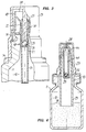
- FIG. 1 and 2 show a metering device 17, which is attached to a container 11 by means of a crimp closure 15, which overlaps a flange 19 of the housing 20 of the metering device, in the interior 12 of which a supply of a powder 16 is contained.
- the container can be a normal bottle with a neck 13 and an opening 14, but other container shapes are also possible.
- the metering device 17 then has on the flange 19 a mouthpiece 18 which is adapted to a body opening exerting a suction effect, for example a nostril or the mouth. It has an opening 28 at its upper end, at which a discharge channel 22 ends. This is provided in an insert 21 which is pressed into the housing 20.
- the housing forms a valve seat 25 of a closure 24.
- the discharge channel has a diameter over a larger distance that is many times longer than a valve body 27 arranged in the form of a ball, which is larger than this ball, so that a flow cross-section 45 surrounding the valve body is formed.
- a further valve seat 26 is provided, on which the valve body 27 rests in its rest position and seals the discharge channel. From this valve seat in the A suction tube 23 extends into the container, which, as indicated by dashed lines, either extends into the powder to near the bottom of the container or, for example in the form of a funnel, has a suction opening 34 in the region of the powder surface 33.
- a cap 19 which is screwed onto a thread of the mouthpiece and closes both the mouth 28 and a ventilation channel 31 opening into the flange 19 between the atmosphere and the container.
- the ventilation duct can be provided as a simple opening in the flange, but it is also possible to connect a pipe 35 there.
- This ventilation tube 35 shown in dash-dotted lines leads below the powder surface and has its mouth there.
- Fig. 3 shows on an enlarged scale an embodiment in which a centrally downwardly projecting pin 30 is attached to the cap 29, which protrudes through the opening of the valve seat 25 and most of the enlarged discharge channel 22 and is dimensioned in this way that in the screwed-on state the lower end face of the pin 30 fixes the valve body 27 on the lower rest valve seat 26.
- the cap 29 is connected to the container 11 by a tamper-evident device 36. It contains a ring which is connected to the cap via predetermined breaking points which are torn open when it is operated for the first time.
- a child lock 37 of a known type is provided which only unscrews the cap 29 from the housing 20 of the metering device 17 after a specific one has been carried out Sequence of operations, for example pressing down the cap and then screwing, allowed.
- the discharge channel 22 is not substantially wider than the valve body diameter in the rest position 50, but then widens conically. This enables safe acceleration of the valve body and a slow start to discharge. A different design of the discharge channel can also be provided to achieve other operating requirements.
- the mouthpiece 18 is not provided here, as in FIGS. 1 and 2, as a nose adapter, but rather as a mouthpiece to be taken into the mouth through which suction can take place. Otherwise, the design is essentially identical to that of FIGS. 1 and 2.
- closure 24a is also provided here at the upper end of the mouthpiece 18 designed as a nose adapter, in the form of a valve seat 25.
- the closure body 27 designed as a ball is provided at the end of a closure body channel 40 which projects centrally in the housing 20, however is not intended to be flowed through by the medium, at least not by the bulk.
- the closure body lies at the end of this closure body channel 40 and is largely adapted to its diameter, so that it can be moved in a manner similar to a piston.
- connection opening 41 is provided which, in the example shown, projects through the suction pipe 23, which in this case has a very large diameter, into an annular gap 43 which extends the ventilation duct 31 and to the Inner circumference of the bottle neck 23 adjoins.
- slots 44 are provided in its otherwise closed outer wall, through which the medium flowing in the annular gap 45 between the inner wall of the housing 20 and the closure body channel 40 flows to the mouth 28 using the upper part of the closure body channel.
- the cap 29 is unscrewed and removed for use.
- the discharge channel 22 is cleared via the mouth 28.
- the metering device can now be attached to a body opening, for example inserted into a nostril with the mouthpiece 18.
- a ventilation tube 35 is used, the air flowing through the ventilation channel 31 into the container and replacing the extracted air flows directly under the surface of the powder and ensures its uniform distribution in the air in the manner of a whirling.
- valve body 27 After the start of the suction, a force acts on the valve body 27 which is generated by pressure differences above and below the valve body. This pressure difference is in turn dependent on the throttling in the flow cross-section and thus on the flow speed. The valve body thus moves upwards in the discharge channel. When he has crossed his movement distance between the two valve seats 25, 26, he lies down in the now reached closed position 51 (FIG. 2) on the upper valve seat 25 of the closure 24 and thus closes off the discharge channel for the suction.
- the user can therefore only suck in as much of the medium (air / solid dispersion) as flows past it through the discharge channel during the time in which the valve body is moving upwards. Since the speed of the valve body is determined by the flow speed, the metered quantity remains relatively constant, even if the suction is different. With a higher suction speed, the quantity per unit of time is larger, but the dosing time is shorter. So there is a certain automatic dosage quantity.
- the function in the embodiment according to FIG. 3 is corresponding. To remove the cap, it is first necessary to break the tamper-evident lock and then to release the child lock.
- the pin 30 gives until then in the Start position blocked, the valve body 26 directly closing the valve body freely. In this case, suction takes place via the mouth, for which purpose the mouthpiece has an appropriate shape.
- the medium flows around the closure body channel 40 and flows through the slots 44 into the closure body channel and through the opening in the valve seat 25.
- a negative pressure is generated in the closure body channel 40, which sucks the valve body 27 upward therein.
- air flows in through the opening 42 from the annular gap 43 and penetrates from the ventilation channel 31.
- the time delay causing the metering is thus determined in the examples shown by the time it takes the valve body to travel the delay distance between its rest position (in FIGS. 1 and 2 on the rest valve seat and in FIG. 3 on the bottom of the closure body channel) Closure valve seat 25 to run.
- this time could also be determined differently, equalized or further delayed, for example by mechanical or other means.
- Other drive means for the valve body 25 are possible.
- valve body itself is preferably a ball, as it is the simplest and least problematic to manufacture and use, a different valve body shape could also be used, for example a valve body with a central pin and two conical or spherical ends, which protrudes through an opening and the ends of which cooperate with valve seats located on both sides of the opening. The length of the pin determines the deceleration distance.
- the dosing device described is particularly advantageous for use in powder / air dispersions, and is preferred there for devices that work with suction from the outside. Dosing is a particular problem with these devices because there is no delivery device for the medium, such as a pump, provided in the metering device itself. However, it is possible to use the metering device in other devices, for example downstream of a liquid atomizer. This can be important, for example, for a device that works with a compressed gas container.
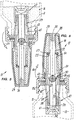
- the basic structure of the metering device according to FIGS. 5 to 8 corresponds to that according to FIGS. 1 and 2.
- the housing 20 of the metering device 17 is screwed onto the container 11 by means of a union nut 15a.
- the housing 20 is shaped into a mouthpiece 18, in the interior of which a discharge channel 22 leads to an opening 28.
- valve body 27 is in the form of a steel ball arranged longitudinally movable. Its two end positions are determined by the valve seats 25 and 26.
- valve seat 25 is located on a valve seat ring 57, which consists of a plastic material with magnetic properties.
- a valve seat ring 57 which consists of a plastic material with magnetic properties.
- known plastics with embedded magnetic particles can be used.
- a suction tube 23 protrudes from the housing 20 into the container, which connects on one side to the valve seat 26 and has an opening 34 on its underside, which is surrounded by a conical tube section 58.
- the annular channel 59 formed between the suction pipe 23 and the pipe section 58 narrows conically towards the mouth 34 and is directed onto a bowl-shaped bottom 60 of a medium template 61, on which the powdered medium 16 collects before being atomized or carried along by the air.
- the tube section 58 is provided in its upper part in FIG. 6 with openings 62 through which the ring channel 59 is connected to the interior 12 of the container.
- the screw cap 15a and the housing 20 have a plurality of ventilation channels 31 on the circumference, which connect the interior of the container 12 to the outside air, but with the interposition of a fine filter 63, which lies like a ring around the outer mouths of the ventilation openings and contamination of the medium by penetration of Prevents germs from outside.
- the cap 29 has a central pin-shaped projection 30 which extends through the entire discharge channel 22 to close to the valve seat 26.
- the dosing device 17 shown is intended for actuation by suction via a patient's mouth or nose.
- the metering device In the idle state, the metering device assumes the position shown in FIG. 6.
- the cap 29 is fitted and the pin 30 holds the valve ball 27 on the valve seat 26, i.e. in the starting position 50.
- the metering device 17 is rotated by tilting through 180 ° (see arrow 64) into the overhead position shown in FIG. 5.
- the medium 16 falls into the neck of the container and fills the collecting chamber 65 which forms in the upper part of the annular channel 59 and adjoins the openings 62.
- the filling of the collecting chamber is limited by the normal pouring cone of the medium (powder).
- the valve ball 27 on the valve seat 26 prevents any medium 16 still present in the antechamber 67 from falling out.
- the metering device is then turned back into the upright position (FIG. 6) (arrow 66).
- the medium 16 falls back into the container, except for the part that falls from the collecting chamber 65 into the conical annular channel 59 and from there into the prechamber 67, the bowl-shaped bottom 60 of which forms the medium template 61.
- the lower valve ie the valve ball 27
- the valve ball opens under the suction that is created lifts off the valve seat 26 and, due to the resistance of the flowing medium / air mixture, the ball moves upwards against the force of gravity in the section 56 of the discharge channel 22.
- a holding means is thus formed in the exemplary embodiment, which could also consist of mechanical or other holders, for example plastic tabs or the like protruding into the flow channel.
- FIGS. 5 to 8 thus permits particularly reliable and uniform atomization with pre-metering and secures the metering device against inadvertent double actuation. It also enables sterile storage of the powder between individual operations.
Landscapes
- Health & Medical Sciences (AREA)
- Engineering & Computer Science (AREA)
- Life Sciences & Earth Sciences (AREA)
- Heart & Thoracic Surgery (AREA)
- Animal Behavior & Ethology (AREA)
- Pulmonology (AREA)
- Anesthesiology (AREA)
- Biomedical Technology (AREA)
- Biophysics (AREA)
- Hematology (AREA)
- Bioinformatics & Cheminformatics (AREA)
- General Health & Medical Sciences (AREA)
- Public Health (AREA)
- Veterinary Medicine (AREA)
- Containers And Packaging Bodies Having A Special Means To Remove Contents (AREA)
- Medical Preparation Storing Or Oral Administration Devices (AREA)
- Nozzles (AREA)
- Auxiliary Methods And Devices For Loading And Unloading (AREA)
- Basic Packing Technique (AREA)
Applications Claiming Priority (2)
| Application Number | Priority Date | Filing Date | Title |
|---|---|---|---|
| DE19613185A DE19613185A1 (de) | 1996-04-02 | 1996-04-02 | Dosiereinrichtung für strömungsfähige Medien wie Pulver/Luft-Dispersionen |
| DE19613185 | 1996-04-02 |
Publications (3)
| Publication Number | Publication Date |
|---|---|
| EP0799646A2 true EP0799646A2 (fr) | 1997-10-08 |
| EP0799646A3 EP0799646A3 (fr) | 1998-09-30 |
| EP0799646B1 EP0799646B1 (fr) | 2002-09-18 |
Family
ID=7790278
Family Applications (1)
| Application Number | Title | Priority Date | Filing Date |
|---|---|---|---|
| EP97105075A Expired - Lifetime EP0799646B1 (fr) | 1996-04-02 | 1997-03-26 | Dispositif de dosage pour une substance apte à s'écouler comme une dispersion air-poudre |
Country Status (6)
| Country | Link |
|---|---|
| US (1) | US6055979A (fr) |
| EP (1) | EP0799646B1 (fr) |
| JP (1) | JPH1028736A (fr) |
| AT (1) | ATE224237T1 (fr) |
| DE (2) | DE19613185A1 (fr) |
| ES (1) | ES2183033T3 (fr) |
Cited By (6)
| Publication number | Priority date | Publication date | Assignee | Title |
|---|---|---|---|---|
| WO1999046055A1 (fr) * | 1998-03-10 | 1999-09-16 | Valois S.A. | Reservoir, procede de remplissage du reservoir et dispositif de distribution du produit fluide contenu dans le reservoir |
| FR2775963A1 (fr) * | 1998-03-10 | 1999-09-17 | Valois Sa | Dispositif pour distribuer unitairement une dose de produit a l'aide d'un ecoulement de gaz sous pression |
| EP2210674A3 (fr) * | 2009-01-23 | 2011-05-18 | Ing. Erich Pfeiffer GmbH | Dispositif de sortie |
| CN103008145A (zh) * | 2012-12-05 | 2013-04-03 | 中山市君禾机电设备有限公司 | 集成粉泵 |
| EP3075405A3 (fr) * | 2013-10-10 | 2017-02-08 | Aptar Radolfzell GmbH | Dispositif de sortie |
| WO2021167967A1 (fr) * | 2020-02-18 | 2021-08-26 | Building Materials Investment Corporation | Système et procédé de revêtement de toit à deux composants assisté par matrice |
Families Citing this family (29)
| Publication number | Priority date | Publication date | Assignee | Title |
|---|---|---|---|---|
| US20060213505A1 (en) * | 1997-11-14 | 2006-09-28 | Astrazeneca Ab | Inhalation device |
| SE9704185D0 (sv) * | 1997-11-14 | 1997-11-14 | Astra Pharma Prod | Inhalation device |
| US7967011B2 (en) * | 1997-11-14 | 2011-06-28 | Astrazeneca Ab | Inhalation device |
| OA11529A (en) | 1998-03-16 | 2004-05-07 | Inhale Therapeutic Syst | Aerosolized active agent delivery. |
| US6260549B1 (en) * | 1998-06-18 | 2001-07-17 | Clavius Devices, Inc. | Breath-activated metered-dose inhaler |
| UA73924C2 (en) * | 1998-10-09 | 2005-10-17 | Nektar Therapeutics | Device for delivering active agent formulation to lungs of human patient |
| US6328033B1 (en) * | 1999-06-04 | 2001-12-11 | Zohar Avrahami | Powder inhaler |
| US6606992B1 (en) * | 1999-06-30 | 2003-08-19 | Nektar Therapeutics | Systems and methods for aerosolizing pharmaceutical formulations |
| US20040115133A1 (en) * | 2000-05-10 | 2004-06-17 | Wermeling Daniel P. | Intranasal opioid compositions |
| SE517225C2 (sv) * | 2000-09-21 | 2002-05-14 | Microdrug Ag | Optimering av en elektrostatiskt doserad inhalator för torrt pulver |
| ZA200306564B (en) * | 2001-02-26 | 2004-10-15 | Optinose As | Nasal devices. |
| JP4371660B2 (ja) * | 2001-04-26 | 2009-11-25 | ニユー・イングランド・フアーマシユーテイカルズ・インコーポレイテツド | 液体状および粉末状薬剤のための定量投与デバイス |
| FR2830240B1 (fr) * | 2001-10-01 | 2004-08-20 | Oreal | Dispositif de conditionnement d'un produit, notamment un produit cosmetique et/ou de soins |
| ATE453421T1 (de) * | 2002-05-09 | 2010-01-15 | Glaxo Group Ltd | Flüssigkeit abgebende vorrichtung |
| US20040040985A1 (en) * | 2002-06-10 | 2004-03-04 | Gatton Brian Michael | Medicament dispensing container closure assembly |
| US7185651B2 (en) * | 2002-06-18 | 2007-03-06 | Nektar Therapeutics | Flow regulator for aerosol drug delivery and methods |
| GB0305583D0 (en) * | 2003-03-11 | 2003-04-16 | Glaxo Group Ltd | A fluid dispensing device |
| US7140522B2 (en) * | 2003-06-26 | 2006-11-28 | Spencer Forrest, Inc. | Applicator for hair building solids |
| US20060021673A1 (en) * | 2004-07-27 | 2006-02-02 | Stephan Rodewald | Self-sealing apparatus for chemical reaction vessel |
| US20060039869A1 (en) * | 2004-08-17 | 2006-02-23 | Daniel Wermeling | Intranasal delivery of antipsychotic drugs |
| JP5047589B2 (ja) * | 2006-10-31 | 2012-10-10 | 株式会社吉野工業所 | 点鼻薬用投薬器 |
| EP2534957B1 (fr) | 2007-12-14 | 2015-05-27 | AeroDesigns, Inc | Administration de produits sous forme d'aérosols |
| DE102008036976A1 (de) * | 2008-08-08 | 2010-02-11 | Behr Gmbh & Co. Kg | Pumpeinrichtung sowie Verfahren zum Betreiben einer Pumpeinrichtung |
| US10463815B2 (en) * | 2012-02-21 | 2019-11-05 | Respira Therapeutics, Inc. | Inhaler to deliver substances for prophylaxis or prevention of disease or injury caused by the inhalation of biological or chemical agents |
| DE102013202933B3 (de) * | 2013-02-22 | 2013-11-14 | Aptar Radolfzell Gmbh | Kindergesicherte Austragvorrichtung |
| FR3066921B1 (fr) * | 2017-06-06 | 2022-06-03 | Aptar France Sas | Dispositif de distribution de produit fluide ou pulverulent. |
| EP3713626A4 (fr) | 2017-11-21 | 2021-08-18 | Impel Neuropharma Inc. | Dispositif intra-nasale avec interface d'entrée |
| FR3075650B1 (fr) * | 2017-12-22 | 2020-01-03 | Aptar France Sas | Dispositif de distribution de produit fluide. |
| DE102021104813A1 (de) * | 2021-03-01 | 2022-09-01 | F+K Innovationen Gmbh & Co. Kg | Dosiereinheit für ein Flüssigkeitsbehältnis |
Family Cites Families (39)
| Publication number | Priority date | Publication date | Assignee | Title |
|---|---|---|---|---|
| DE558018C (de) * | 1932-08-31 | Otto Vieli | Selbsttaetig sich schliessendes Ventil mit mechanisch von dem Ventilsitz abhebbarem Ventilkoerper, insbesondere fuer Spuelanlagen | |
| AT35055B (de) * | 1904-07-04 | 1908-11-10 | Graaff & Cie Ges Mit Beschr Ha | Farbenzerstäuber. |
| US1873260A (en) * | 1929-12-19 | 1932-08-23 | John O Barce | Valve |
| US2122234A (en) * | 1936-10-01 | 1938-06-28 | Manning Lab | Applicator |
| US2202079A (en) * | 1939-03-13 | 1940-05-28 | Ayres Waldemar | Dispenser |
| US2358329A (en) * | 1941-08-21 | 1944-09-19 | Double Duty Products Inc | Dispensing closure structure |
| US2501047A (en) * | 1945-10-20 | 1950-03-21 | Binks Mfg Co | Dry powder sprayer |
| BE483136A (fr) * | 1947-09-04 | 1942-06-30 | ||
| US2570774A (en) * | 1947-10-21 | 1951-10-09 | Frank P C Davis | Insufflator |
| US2642063A (en) * | 1948-07-31 | 1953-06-16 | Frederick M Turnbull | Inhaler |
| US2641255A (en) * | 1949-03-31 | 1953-06-09 | Abbott Lab | Inhaler |
| US2549303A (en) * | 1949-04-20 | 1951-04-17 | Bristol Lab Inc | Inhaler for crystalline pencilllin or the like |
| GB674355A (en) * | 1949-06-01 | 1952-06-25 | Squeez Easy Dispenser And Cont | Collapsible dispensing container |
| US2579280A (en) * | 1949-06-25 | 1951-12-18 | Macgregor Instr Company | Inhaler |
| DE1033147B (de) * | 1955-11-21 | 1958-06-26 | Wilhelm Waldherr | Dosierventil mit Spruehkopf fuer Spruehdosen oder Flaschen |
| FR1219745A (fr) * | 1958-04-09 | 1960-05-19 | Perfectionnements aux distributeurs de fluide sous pression | |
| DE1147668B (de) * | 1959-12-11 | 1963-04-25 | Siemens Ag | Einrichtung zum Anhalten der Arbeitsspindel einer Maschine in einer bestimmten Winkelstellung |
| DE1500167A1 (de) * | 1965-12-14 | 1969-04-24 | Karl Meier | Absperrorgan,insbesondere Wasserhahn |
| US3840184A (en) * | 1973-11-01 | 1974-10-08 | A Spivey | Spray gun |
| US4007858A (en) * | 1976-02-17 | 1977-02-15 | Summit Packaging Systems, Inc. | Squeeze-bottle-type powder dispenser |
| DE7800713U1 (de) * | 1978-01-11 | 1978-05-24 | Schnabel, Ernst, Dr., 6250 Limburg | Metallrohr mit einer kunststoffauskleidung und einer halterung fuer ein loses bauteil |
| US4286735A (en) * | 1979-08-14 | 1981-09-01 | Sneider Vincent R | Squeeze dispenser with flexible conduit with attached, weighted and grooved end |
| US4261488A (en) * | 1979-09-10 | 1981-04-14 | Bennett Robert A | Powder entraining squeeze container |
| US4657007A (en) * | 1982-06-28 | 1987-04-14 | Whittaker General Medical Corporation | Nebulizer |
| DE3244836C2 (de) * | 1982-12-03 | 1984-09-27 | Bosch-Siemens Hausgeräte GmbH, 7000 Stuttgart | Inhaliervorrichtung mit einer Dosiereinrichtung für Inhalate |
| FR2547737B1 (fr) * | 1983-06-24 | 1988-04-08 | Valois Sa | Embout-poussoir pour pulverisateur medical |
| DE3517558A1 (de) * | 1985-05-15 | 1986-11-20 | Ing. Erich Pfeiffer GmbH & Co KG, 7760 Radolfzell | Handbetaetigte ausgabeeinrichtung fuer medien |
| DE3520748C1 (de) * | 1985-06-10 | 1986-07-31 | Feodor Burgmann Dichtungswerke Gmbh & Co, 8190 Wolfratshausen | Fluessigkeits-Mengenmesser bzw. Durchflussmesser |
| US4815414A (en) * | 1987-04-20 | 1989-03-28 | Nylok Fastener Corporation | Powder spray apparatus |
| DE8707725U1 (de) * | 1987-05-29 | 1987-07-30 | Otto, Roland, 8752 Kleinostheim | Druckluftpistole |
| DE3901110A1 (de) * | 1989-01-16 | 1990-07-19 | Krupp Polysius Ag | Pneumatischer senkrechtfoerderer |
| DE4004904A1 (de) * | 1990-02-16 | 1990-09-13 | Gerhard Brendel | Trommel-applikator |
| DE4027749A1 (de) * | 1990-09-01 | 1992-03-05 | Pfeiffer Erich Gmbh & Co Kg | Austragvorrichtung fuer medien |
| DE4128295A1 (de) * | 1991-08-27 | 1993-03-04 | Pfeiffer Erich Gmbh & Co Kg | Austragvorrichtung fuer fliessfaehige medien |
| US5341801A (en) * | 1991-12-03 | 1994-08-30 | Sandoz Ltd. | Inhaler |
| DE4201665C2 (de) * | 1992-01-22 | 1993-10-28 | Wagner International Ag Altsta | Pulver-Injektor |
| DE9312772U1 (de) * | 1993-08-26 | 1993-10-14 | Gustav Wahler Gmbh U. Co, 73730 Esslingen | Rückschlagventil |
| IT1266794B1 (it) * | 1993-11-09 | 1997-01-21 | Faustino Ballini | Dispositivo a doccia micronizzata per il lavaggio delle cavita' nasali e limitrofe |
| DE4415462C1 (de) * | 1994-05-03 | 1995-08-31 | Transcoject Marketing Gmbh | Inhalator |
-
1996
- 1996-04-02 DE DE19613185A patent/DE19613185A1/de not_active Withdrawn
-
1997
- 1997-03-26 AT AT97105075T patent/ATE224237T1/de not_active IP Right Cessation
- 1997-03-26 ES ES97105075T patent/ES2183033T3/es not_active Expired - Lifetime
- 1997-03-26 DE DE59708223T patent/DE59708223D1/de not_active Expired - Lifetime
- 1997-03-26 EP EP97105075A patent/EP0799646B1/fr not_active Expired - Lifetime
- 1997-04-01 JP JP9096385A patent/JPH1028736A/ja active Pending
- 1997-04-01 US US08/831,100 patent/US6055979A/en not_active Expired - Fee Related
Cited By (10)
| Publication number | Priority date | Publication date | Assignee | Title |
|---|---|---|---|---|
| WO1999046055A1 (fr) * | 1998-03-10 | 1999-09-16 | Valois S.A. | Reservoir, procede de remplissage du reservoir et dispositif de distribution du produit fluide contenu dans le reservoir |
| FR2775963A1 (fr) * | 1998-03-10 | 1999-09-17 | Valois Sa | Dispositif pour distribuer unitairement une dose de produit a l'aide d'un ecoulement de gaz sous pression |
| US6398074B1 (en) | 1998-03-10 | 2002-06-04 | Valois S.A. | Reservoir, reservoir filling method and device for dispensing fluid contained in the reservoir |
| CN1106888C (zh) * | 1998-03-10 | 2003-04-30 | 瓦卢瓦股份有限公司 | 容器、容器的灌注方法及容器中流体制品的分配装置 |
| EP2210674A3 (fr) * | 2009-01-23 | 2011-05-18 | Ing. Erich Pfeiffer GmbH | Dispositif de sortie |
| US8292129B2 (en) | 2009-01-23 | 2012-10-23 | Ing. Erich Pfeiffer Gmbh | Dispensing device |
| CN103008145A (zh) * | 2012-12-05 | 2013-04-03 | 中山市君禾机电设备有限公司 | 集成粉泵 |
| EP3075405A3 (fr) * | 2013-10-10 | 2017-02-08 | Aptar Radolfzell GmbH | Dispositif de sortie |
| US10835692B2 (en) | 2013-10-10 | 2020-11-17 | Aptar Radolfzell Gmbh | Childproof discharging device |
| WO2021167967A1 (fr) * | 2020-02-18 | 2021-08-26 | Building Materials Investment Corporation | Système et procédé de revêtement de toit à deux composants assisté par matrice |
Also Published As
| Publication number | Publication date |
|---|---|
| JPH1028736A (ja) | 1998-02-03 |
| EP0799646B1 (fr) | 2002-09-18 |
| ES2183033T3 (es) | 2003-03-16 |
| DE59708223D1 (de) | 2002-10-24 |
| ATE224237T1 (de) | 2002-10-15 |
| EP0799646A3 (fr) | 1998-09-30 |
| DE19613185A1 (de) | 1997-10-09 |
| US6055979A (en) | 2000-05-02 |
Similar Documents
| Publication | Publication Date | Title |
|---|---|---|
| EP0799646B1 (fr) | Dispositif de dosage pour une substance apte à s'écouler comme une dispersion air-poudre | |
| EP0473965B1 (fr) | Distributeur pour substances | |
| EP1523365B1 (fr) | Inhalateur à actionnement manuel pour substances pulvérulentes | |
| EP1027165B1 (fr) | Procede permettant de distribuer au moins deux produits differents et distributeur a cet effet | |
| EP1220700B1 (fr) | Inhalateur de respiration controlée pour poudre | |
| EP0667793B1 (fr) | Procede et dispositif permettant de produire un aerosol a partir d'une substance pulverulente | |
| DE69723202T2 (de) | Inhalatoren | |
| DE69102928T2 (de) | Einrichtung zur Verabreichung pulverisierter medizinischer Substanzen. | |
| DE60115689T2 (de) | Trockenpulverinhalator | |
| DE69918325T2 (de) | Atmungsbetätigte aerosolspender | |
| DE2106794A1 (de) | Vorrichtung zum Apphzieren einer abgemessenen Pulvermenge unter Druck | |
| DE1625197A1 (de) | Verteiler | |
| CH656311A5 (de) | Durch atemluft betaetigte vorrichtung zum oralen inhalieren eines medikamentes in pulverform. | |
| DE7340215U (de) | Inhalator fuer fluessige medikamente mit einer zerstaeubungskammer und dafuer bestimmte fuellphiole | |
| EP0844007A2 (fr) | Distributeur de produit | |
| DE2600862A1 (de) | Inhalationseinrichtung | |
| DE2600855A1 (de) | Inhaliervorrichtung | |
| DE102005010965B3 (de) | Inhalator mit einem Mischkanal zum Erzeugen eines zu inhalierenden Aerosols | |
| WO2009149727A1 (fr) | Dispositif de dosage et procédé d’utilisation de ce dispositif de dosage | |
| DE60208535T2 (de) | Abfüllkopf | |
| DE69824327T2 (de) | Inhalationsgerät | |
| WO2009059894A1 (fr) | Appareil manuel d'ihhalation de substances | |
| DE2434421A1 (de) | Vorrichtung zum verabreichen von pulvern | |
| DE3751272T2 (de) | Inhalationsvorrichtung und Methode. | |
| DE2215348C2 (de) | Sprüheinsatz |
Legal Events
| Date | Code | Title | Description |
|---|---|---|---|
| PUAI | Public reference made under article 153(3) epc to a published international application that has entered the european phase |
Free format text: ORIGINAL CODE: 0009012 |
|
| AK | Designated contracting states |
Kind code of ref document: A2 Designated state(s): AT CH DE ES FR GB IE IT LI SE |
|
| PUAL | Search report despatched |
Free format text: ORIGINAL CODE: 0009013 |
|
| AK | Designated contracting states |
Kind code of ref document: A3 Designated state(s): AT CH DE ES FR GB IE IT LI SE |
|
| 17P | Request for examination filed |
Effective date: 19981212 |
|
| 17Q | First examination report despatched |
Effective date: 19990708 |
|
| GRAG | Despatch of communication of intention to grant |
Free format text: ORIGINAL CODE: EPIDOS AGRA |
|
| GRAG | Despatch of communication of intention to grant |
Free format text: ORIGINAL CODE: EPIDOS AGRA |
|
| GRAH | Despatch of communication of intention to grant a patent |
Free format text: ORIGINAL CODE: EPIDOS IGRA |
|
| GRAH | Despatch of communication of intention to grant a patent |
Free format text: ORIGINAL CODE: EPIDOS IGRA |
|
| GRAA | (expected) grant |
Free format text: ORIGINAL CODE: 0009210 |
|
| AK | Designated contracting states |
Kind code of ref document: B1 Designated state(s): AT CH DE ES FR GB IE IT LI SE |
|
| PG25 | Lapsed in a contracting state [announced via postgrant information from national office to epo] |
Ref country code: IE Free format text: LAPSE BECAUSE OF FAILURE TO SUBMIT A TRANSLATION OF THE DESCRIPTION OR TO PAY THE FEE WITHIN THE PRESCRIBED TIME-LIMIT Effective date: 20020918 |
|
| REF | Corresponds to: |
Ref document number: 224237 Country of ref document: AT Date of ref document: 20021015 Kind code of ref document: T |
|
| REG | Reference to a national code |
Ref country code: GB Ref legal event code: FG4D Free format text: NOT ENGLISH |
|
| REG | Reference to a national code |
Ref country code: CH Ref legal event code: EP |
|
| GBT | Gb: translation of ep patent filed (gb section 77(6)(a)/1977) |
Effective date: 20020918 |
|
| REG | Reference to a national code |
Ref country code: IE Ref legal event code: FG4D Free format text: GERMAN |
|
| REF | Corresponds to: |
Ref document number: 59708223 Country of ref document: DE Date of ref document: 20021024 |
|
| REG | Reference to a national code |
Ref country code: CH Ref legal event code: NV Representative=s name: ZIMMERLI, WAGNER & PARTNER AG |
|
| REG | Reference to a national code |
Ref country code: ES Ref legal event code: FG2A Ref document number: 2183033 Country of ref document: ES Kind code of ref document: T3 |
|
| PG25 | Lapsed in a contracting state [announced via postgrant information from national office to epo] |
Ref country code: AT Free format text: LAPSE BECAUSE OF NON-PAYMENT OF DUE FEES Effective date: 20030326 |
|
| ET | Fr: translation filed | ||
| REG | Reference to a national code |
Ref country code: IE Ref legal event code: FD4D Ref document number: 0799646E Country of ref document: IE |
|
| PLBE | No opposition filed within time limit |
Free format text: ORIGINAL CODE: 0009261 |
|
| STAA | Information on the status of an ep patent application or granted ep patent |
Free format text: STATUS: NO OPPOSITION FILED WITHIN TIME LIMIT |
|
| 26N | No opposition filed |
Effective date: 20030619 |
|
| PGFP | Annual fee paid to national office [announced via postgrant information from national office to epo] |
Ref country code: ES Payment date: 20060320 Year of fee payment: 10 |
|
| PGFP | Annual fee paid to national office [announced via postgrant information from national office to epo] |
Ref country code: SE Payment date: 20080320 Year of fee payment: 12 |
|
| REG | Reference to a national code |
Ref country code: ES Ref legal event code: FD2A Effective date: 20070327 |
|
| PG25 | Lapsed in a contracting state [announced via postgrant information from national office to epo] |
Ref country code: ES Free format text: LAPSE BECAUSE OF NON-PAYMENT OF DUE FEES Effective date: 20070327 |
|
| REG | Reference to a national code |
Ref country code: CH Ref legal event code: PFA Owner name: ING. ERICH PFEIFFER GMBH Free format text: ING. ERICH PFEIFFER GMBH#OESCHLESTRASSE 124-126#78315 RADOLFZELL (DE) -TRANSFER TO- ING. ERICH PFEIFFER GMBH#OESCHLESTRASSE 124-126#78315 RADOLFZELL (DE) |
|
| EUG | Se: european patent has lapsed | ||
| PG25 | Lapsed in a contracting state [announced via postgrant information from national office to epo] |
Ref country code: SE Free format text: LAPSE BECAUSE OF NON-PAYMENT OF DUE FEES Effective date: 20090327 |
|
| PGFP | Annual fee paid to national office [announced via postgrant information from national office to epo] |
Ref country code: CH Payment date: 20110328 Year of fee payment: 15 Ref country code: FR Payment date: 20110401 Year of fee payment: 15 |
|
| PGFP | Annual fee paid to national office [announced via postgrant information from national office to epo] |
Ref country code: GB Payment date: 20110324 Year of fee payment: 15 Ref country code: DE Payment date: 20110322 Year of fee payment: 15 |
|
| PGFP | Annual fee paid to national office [announced via postgrant information from national office to epo] |
Ref country code: IT Payment date: 20110329 Year of fee payment: 15 |
|
| REG | Reference to a national code |
Ref country code: CH Ref legal event code: PL |
|
| GBPC | Gb: european patent ceased through non-payment of renewal fee |
Effective date: 20120326 |
|
| REG | Reference to a national code |
Ref country code: FR Ref legal event code: ST Effective date: 20121130 |
|
| REG | Reference to a national code |
Ref country code: DE Ref legal event code: R119 Ref document number: 59708223 Country of ref document: DE Effective date: 20121002 |
|
| PG25 | Lapsed in a contracting state [announced via postgrant information from national office to epo] |
Ref country code: GB Free format text: LAPSE BECAUSE OF NON-PAYMENT OF DUE FEES Effective date: 20120326 Ref country code: FR Free format text: LAPSE BECAUSE OF NON-PAYMENT OF DUE FEES Effective date: 20120402 Ref country code: CH Free format text: LAPSE BECAUSE OF NON-PAYMENT OF DUE FEES Effective date: 20120331 Ref country code: LI Free format text: LAPSE BECAUSE OF NON-PAYMENT OF DUE FEES Effective date: 20120331 |
|
| PG25 | Lapsed in a contracting state [announced via postgrant information from national office to epo] |
Ref country code: IT Free format text: LAPSE BECAUSE OF NON-PAYMENT OF DUE FEES Effective date: 20120326 |
|
| PG25 | Lapsed in a contracting state [announced via postgrant information from national office to epo] |
Ref country code: DE Free format text: LAPSE BECAUSE OF NON-PAYMENT OF DUE FEES Effective date: 20121002 |