EP0800959A2 - Airbagvorrichtung - Google Patents
Airbagvorrichtung Download PDFInfo
- Publication number
- EP0800959A2 EP0800959A2 EP97302360A EP97302360A EP0800959A2 EP 0800959 A2 EP0800959 A2 EP 0800959A2 EP 97302360 A EP97302360 A EP 97302360A EP 97302360 A EP97302360 A EP 97302360A EP 0800959 A2 EP0800959 A2 EP 0800959A2
- Authority
- EP
- European Patent Office
- Prior art keywords
- air bag
- panel
- inflatable air
- peripheral seam
- cover
- Prior art date
- Legal status (The legal status is an assumption and is not a legal conclusion. Google has not performed a legal analysis and makes no representation as to the accuracy of the status listed.)
- Ceased
Links
- 230000002093 peripheral effect Effects 0.000 claims abstract description 40
- 239000002356 single layer Substances 0.000 claims abstract description 4
- 239000000853 adhesive Substances 0.000 claims description 7
- 230000001070 adhesive effect Effects 0.000 claims description 7
- 239000012530 fluid Substances 0.000 claims description 3
- 230000000149 penetrating effect Effects 0.000 claims description 2
- 238000009958 sewing Methods 0.000 description 4
- 238000000034 method Methods 0.000 description 3
- 230000000717 retained effect Effects 0.000 description 3
- 239000004831 Hot glue Substances 0.000 description 2
- 239000004744 fabric Substances 0.000 description 2
- 238000005096 rolling process Methods 0.000 description 2
- 229920001169 thermoplastic Polymers 0.000 description 2
- 229920001187 thermosetting polymer Polymers 0.000 description 2
- 239000004416 thermosoftening plastic Substances 0.000 description 2
- 238000007599 discharging Methods 0.000 description 1
- 238000012986 modification Methods 0.000 description 1
- 230000004048 modification Effects 0.000 description 1
- 239000011347 resin Substances 0.000 description 1
- 229920005989 resin Polymers 0.000 description 1
Images



Classifications
-
- B—PERFORMING OPERATIONS; TRANSPORTING
- B60—VEHICLES IN GENERAL
- B60R—VEHICLES, VEHICLE FITTINGS, OR VEHICLE PARTS, NOT OTHERWISE PROVIDED FOR
- B60R21/00—Arrangements or fittings on vehicles for protecting or preventing injuries to occupants or pedestrians in case of accidents or other traffic risks
- B60R21/02—Occupant safety arrangements or fittings, e.g. crash pads
- B60R21/16—Inflatable occupant restraints or confinements designed to inflate upon impact or impending impact, e.g. air bags
- B60R21/23—Inflatable members
- B60R21/231—Inflatable members characterised by their shape, construction or spatial configuration
- B60R21/2334—Expansion control features
- B60R21/2338—Tethers
-
- B—PERFORMING OPERATIONS; TRANSPORTING
- B60—VEHICLES IN GENERAL
- B60R—VEHICLES, VEHICLE FITTINGS, OR VEHICLE PARTS, NOT OTHERWISE PROVIDED FOR
- B60R21/00—Arrangements or fittings on vehicles for protecting or preventing injuries to occupants or pedestrians in case of accidents or other traffic risks
- B60R21/02—Occupant safety arrangements or fittings, e.g. crash pads
- B60R21/16—Inflatable occupant restraints or confinements designed to inflate upon impact or impending impact, e.g. air bags
- B60R21/23—Inflatable members
- B60R21/231—Inflatable members characterised by their shape, construction or spatial configuration
- B60R21/2334—Expansion control features
- B60R21/2342—Tear seams
-
- B—PERFORMING OPERATIONS; TRANSPORTING
- B60—VEHICLES IN GENERAL
- B60R—VEHICLES, VEHICLE FITTINGS, OR VEHICLE PARTS, NOT OTHERWISE PROVIDED FOR
- B60R21/00—Arrangements or fittings on vehicles for protecting or preventing injuries to occupants or pedestrians in case of accidents or other traffic risks
- B60R21/02—Occupant safety arrangements or fittings, e.g. crash pads
- B60R21/16—Inflatable occupant restraints or confinements designed to inflate upon impact or impending impact, e.g. air bags
- B60R21/23—Inflatable members
- B60R21/239—Inflatable members characterised by their venting means
-
- B—PERFORMING OPERATIONS; TRANSPORTING
- B60—VEHICLES IN GENERAL
- B60R—VEHICLES, VEHICLE FITTINGS, OR VEHICLE PARTS, NOT OTHERWISE PROVIDED FOR
- B60R21/00—Arrangements or fittings on vehicles for protecting or preventing injuries to occupants or pedestrians in case of accidents or other traffic risks
- B60R21/02—Occupant safety arrangements or fittings, e.g. crash pads
- B60R21/16—Inflatable occupant restraints or confinements designed to inflate upon impact or impending impact, e.g. air bags
- B60R21/23—Inflatable members
- B60R21/231—Inflatable members characterised by their shape, construction or spatial configuration
- B60R21/2334—Expansion control features
- B60R21/2338—Tethers
- B60R2021/23382—Internal tether means
Definitions
- the present invention relates to an air bag device, and particularly to an air bag to be installed on the driver's side of a vehicle.
- An air bag device includes an inflatable air bag that is normally folded, and an igniter for inflating the air bag.
- an inflatable air bag is secured to a mounting positioned in the middle of a steering wheel, and is retained within a cover.
- gas is generated by the igniter, expanding the air bag.
- Expansion of the air bag ruptures and spreads the cover, allowing the air bag to be unfurled between the steering wheel and the occupants in the vehicle. It is desirable in the field of air bag devices to modulate the rate at which the air bag expands toward the occupant when the igniter is actuated, rather than allowing unrestrained expansion toward the occupant.
- Fig. 12 is a perspective view showing an inflated state of a known air bag for the driver's seat
- Fig. 13 is a cross sectional view showing tethers, as described above, used in the known air bag device.
- the air bag 10 shown in Fig. 12 has a first panel 11 and a second panel 12, each consisting of a circular cloth.
- the panels 11,12 are sewed together at a peripheral seam 15.
- the second panel 12 has an opening 14 formed in a middle portion thereof, through which an igniter 34 (Fig. 13) extends.
- the second panel 12 further has a vent hole 18 adapted to release the gas generated by the igniter and stored in the air bag 10.
- the inflatable air bag 10 is secured by bolts, pins or rivets 31 to the mounting 30, and is retained within a cover 32.
- the first panel 11 and the second panel 12 are connected to each other, by tethers 22 that are shortened by folding to create tether folds 26.
- the tether folds 26 are stitched together with sewing threads 24.
- the air bag 10 is unfurled at a relatively low rate, since the peripheral seam 15 at the maximum diameter of the air bag 10 pushes open the cover 32 while being pressed against the inside wall of the cover 32 until the peripheral seam 15 reaches the opening 33 of the cover 32. Then, the air bag 10 is rapidly unfurled once the peripheral seam 15 of the air bag 10 is ejected out of the opening 33 in the cover 32 since the friction between the peripheral seam 15 and the inside wall of the cover 32 has been eliminated. Thus, the whole air bag 10 is deployed outside the cover 32, as shown in Fig. 13. At this point in time, the air bag 10 is prevented from being pushed toward the occupant (i.e., upward in Fig.
- the peripheral seam 15 having the maximum diameter is pressed against the inside of the cover 32 with the resulting friction between the air bag 10 and the inner wall of the cover 32 slowing the rate at which the air bag 10 is unfurled.
- the peripheral seam 15 is ejected outside of the cover 32, however, the resistance to unfurling due to the above-described friction is eliminated, and the remainder of expansion by the air bag 10 is unrestrained, exerting strong tensile forces on local parts of the air bag. Therefore, the panels 11,12 of the air bag 10 are required to have a thickness large enough to resist the localized tensile force.
- the second panel of the air bag is provided with means for modulating the unfurling action of the air bag so that the air bag is unfurled at a relatively low rate, even after the peripheral seam of the air bag is outside the normal cover for the inflatable air bag. More specifically, the second panel is formed with stitched or bonded portions, or tethers are provided between the peripheral seam of the air bag and the mounting. Further, only a single layer of the first panel of the air bag is disposed between the igniter and the vehicle occupant.
- the peripheral seam of the air bag when located within the cover, pushes open the cover while sliding along the inner side wall of the cover against the friction therebetween, so that the first panel is slowly unfurled outward through an opening in the cover.
- the above-indicated means associated with the second panel modulates the unfurling action of the air bag in the lateral direction and toward the vehicle occupant, so that the air bag can be unfurled at a lower rate, thus maintaining a uniform tensile force in the air bag during the unfurling action.
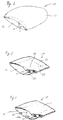
- Fig. 1 through Fig. 3 illustrate a process of fabricating an inflatable air bag 10 constructed according to one embodiment of the present invention in which frangible stitching links folds of a second panel 12.
- the inflatable air bag 10 includes the second panel 12 and a first panel 11, having a front surface 21, a back surface 22 and an edge 23 connecting the front and back surfaces 21,22.
- the second panel 12 is secured to the back surface 22, such as by sewing, to form a peripheral seam 15 proximate to the edge 23 of the first panel 11.
- the peripheral seam 15 delimits the interior space between the first and second panels 11,12 of the inflatable air bag 10.
- the peripheral seam 15 securing the first and second panels 11,12 may be located in the interior space within the inflatable air bag 10, as in the embodiment of Fig. 1, or located outside the interior space within the inflatable air bag 10, as shown in Fig. 13. With the peripheral seam 15 located outside the interior space, the second panel 12 confronts the back surface 22.
- the peripheral seam 15 can be located inside the interior space by inverting (i.e. turn inside-out) the inflatable air bag 10 such that the second panel 12 confronts the front surface 21.
- an arcuate part of the inflatable air bag 10 is folded inward, as indicated by an arrow in Fig. 1.
- the second panel 12 may also be folded inward at a plurality of additional locations.
- Fig. 2 shows a total of four folds, thereby providing an inflatable air bag 10 having a generally square shape when viewed from above.
- the broken lines of Fig. 2 indicate the peripheries of the second panel 12 that are folded inside.
- Fig. 3 the folds of the second panel 12 that are superposed on each other are sewed together with frangible threads 13a to thus form a stitched portion 13. While the present embodiment has only one stitched portion 13, as shown in Fig. 3, similar stitched portions 13 may be provided in additional folds of the second panel 12.
- the second panel 12 and rest of the inflatable air bag 10 shown in Fig. 3 may be folded one or more addition times.
- inflatable air bag 10 may be further folded into a compact size to be accommodated in a cover 32.
- the peripheral seam 15 of the inflatable air bag 10 may be folded up in various manners, such as by rolling (Fig. 5A), rolling and folding in a zigzag (Fig. 5B), or folding in a zigzag fashion (Fig. 5C), so that the inflatable air bag 10 is accommodated in the cover 32.
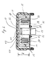
- FIG. 6 is a cross sectional view showing the first embodiment of the present invention.
- the inflatable air bag 10 is formed by sewing the first panel 11 and the second panel 12 to form the peripheral seam 15 outside the interior space of the inflatable air bag 10.
- the second panel 12 includes superposed folds that are sewed together with frangible threads 13a to form stitched portions 13.
- Igniter 34 having gas outlet holes 35 is mounted along with the second panel 12 on mounting 30.
- the cover 32 is also fixed at its perimeter to the mounting 30.
- the cover 32 is formed to create an opening 33 in the middle thereof.
- the inflatable air bag 10 is accommodated or retained in a space 40 defined by the igniter 34, mounting 30 and the cover 32.
- the igniter 34 extends into the space 40 slightly less than the distance "d" between the mounting 30 and the cover 32.
- a single layer of the first panel 11 is present in a gap 42 defined between the end of the igniter 34 and the cover 32. This arrangement makes it possible to smoothly unfurl the first panel 11 as described later.
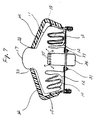
- Fig. 7 shows an expanding state of the air bag device in which the igniter 34 starts discharging a gaseous fluid through the gas outlet holes 35, as indicated by the arrows.
- the gas discharge from the igniter 34 causes cover 32 to rupture creating opening 33 in the cover 32, and a middle portion 17 of the first panel 11 starts unfurling or projecting through opening 33, such that the projected part of the first panel 11 assumes an elliptic shape in cross section.
- the peripheral seam 15 of the first and second panels 11,12 is pressed against the inside wall of the cover 32 due to the gas pressure within the air bag 10, while proceeding toward the opening 33 of the cover 32.
- Fig. 8 shows a more advanced operating state of the air bag device in which the peripheral seam 15 of the air bag 10 is ejected from the opening 33 of the cover 32.
- the frsangible stitches 13a formed in the second panel 12 restrain the entire first and second panels 11,12 from popping out or immediately projecting outward.
- the frangible threads 13a of the stitched portions 13 are then successively broken as the gas pressure created by the inflater 34 increases, whereby the first and second panels 11,12 are progressively unfurled to project outside the cover 32.
- the unfurling action of the air bag 10 is completed when all the frangible threads 13a are broken.
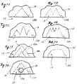
- the pattern of stitches formed with the frangible threads 13a at the stitched portions 13 of the folded second panel 12 may be selected from various patterns, such as a mountain-like pattern (Fig. 9A), a two-mountain-like pattern (Fig. 9B), a three-mountain-like pattern (Fig. 9C), a four-mountain-like pattern (Fig. 9D), a double-mountain-like pattern (Fig. 9E), or a semicircular pattern (Fig. 9F).
- vent hole 18 penetrating the second panel 12 is provided outside the stitched portion 13 in the embodiment of Fig. 3, the vent hole 18 may be circumscribed by the frangible threads 13a as shown in Fig. 9G. In this arrangement, gas is prevented from being discharged through the vent hole 18 while the first panel 11 is unfurled, thus efficiently making use of the gas generated by the igniter 34.
- the stitched portions 13 are provided in the second panel 12 so as to reduce the rate or speed at which the second panel 12 is unfurled out of the cover 32.
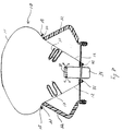
- These stitched portions may be replaced by tethers 51 as shown in Fig. 10.
- the tethers 51 are attached at one end to the peripheral seam 15 of the first and second panels 11,12, and at the other end to the mounting 30, and each of the tethers 51 includes a stitched portion 52 formed in the middle thereof with frangible threads.
- the tethers 51 may be mounted outside the interior space of inflatable air bag 10, or inside the interior space of air bag 10 as shown in Fig. 10.
- a plurality of tethers 51 are attached at equally spaced-apart around the peripheral seam 15 of the first and second panels 11,12.
- the other structure of the inflatable air bag 10 of this embodiment is identical with that of the embodiment of Figs. 6-8. It is to be understood that the manner of folding the air bag 10 is not limited to that as described above referring to Fig. 1 through Fig. 5.
- Fig. 10 shows an operating state of the air bag device in which the first panel 11 is pushed out of the cover 32 under the pressure of the gas discharged from the gas outlet holes 35 of the igniter 34, and the peripheral seam 15 of the air bag device having the maximum diameter reaches the outside of the cover 32 through opening 33.
- the stitched portions 52 of the tethers 51 restrain the first panel 11 and the second panel 12 from popping out or immediately projecting outward.
- the frangible threads forming the stitched portions 52 are successively broken, whereby the first and second panels 11,12 are progressively unfurled to project outside the cover 32.
- the unfurling action of the air bag 10 is completed when all the frangible threads are broken.
- Fig. 11 shows another embodiment of the present invention in which folds of the second panel 12 that are superposed on each other are bonded together to provide bonded portions 61.
- an adhesive used for forming the bonded portions 61 may be selected from known thermoplastic adhesives, such as a hot melt adhesive, which are fused by heat of high-temperature gas discharged from the igniter 34, and known thermosetting resin adhesives that are dissolved and degraded by application of heat.
- Fig. 11 shows another embodiment of the present invention in which folds of the second panel 12 that are superposed on each other are bonded together to provide bonded portions 61.
- an adhesive used for forming the bonded portions 61 may be selected from known thermoplastic adhesives, such as a hot melt adhesive, which are fused by heat of high-temperature gas discharged from the igniter 34, and known thermosetting resin adhesives that are dissolved and degraded by application of heat.
- the bonded portions 61 prevent the first panel 11 and the second panel 12 from immediately projecting outward.
- the pressure within the air bag increases with an increase in the amount of gas discharged from the gas outlet holes 35 of the igniter 34, the bonded portions 61 gradually separate due to the heat of the gas, whereby the first and second panels 11,12 are progressively unfurled to project outside the cover 32.
- the unfurling action of the air bag 10 is completed when the entirety of the bonded portions 61 are separated.
- the bonded portions 61 may be provided in the same patterns as indicated in Figs. 9A-9F in which the stitched portions 13 are provided in the first embodiment.
- stitched portions 52 of the tethers 51 used in the embodiment of Fig. 10 may be replaced by bonded portions formed as described above.
- the second panel of the air bag is provided with means for modulating the unfurling action of the second panel.
- the stitched portions or bonded portions restrain the air bag from abruptly projecting or expanding in the lateral direction after the peripheral seam having the maximum diameter comes out of the cover.
- the air bag can be slowly unfolded in the lateral direction and toward the vehicle occupants, without applying strong tensile forces to local parts of the air bag.
- This allows the air bag to be formed from a cloth having a reduced thickness, leading to reduction in the size and weight of the air bag. Accordingly, the present air bag device can be manufactured at a reduced cost.
Landscapes
- Engineering & Computer Science (AREA)
- Mechanical Engineering (AREA)
- Air Bags (AREA)
Applications Claiming Priority (2)
| Application Number | Priority Date | Filing Date | Title |
|---|---|---|---|
| US1501596P | 1996-04-08 | 1996-04-08 | |
| US15015 | 1996-04-08 |
Publications (2)
| Publication Number | Publication Date |
|---|---|
| EP0800959A2 true EP0800959A2 (de) | 1997-10-15 |
| EP0800959A3 EP0800959A3 (de) | 1998-09-16 |
Family
ID=21769091
Family Applications (1)
| Application Number | Title | Priority Date | Filing Date |
|---|---|---|---|
| EP97302360A Ceased EP0800959A3 (de) | 1996-04-08 | 1997-04-07 | Airbagvorrichtung |
Country Status (3)
| Country | Link |
|---|---|
| US (1) | US5979937A (de) |
| EP (1) | EP0800959A3 (de) |
| JP (1) | JP3769831B2 (de) |
Cited By (4)
| Publication number | Priority date | Publication date | Assignee | Title |
|---|---|---|---|---|
| WO1999056941A1 (en) * | 1998-05-05 | 1999-11-11 | The Procter & Gamble Company | Discontinuously expandable web materials |
| EP1391352A3 (de) * | 2002-08-22 | 2005-03-09 | Nihon Plast Co., Ltd. | Airbag für Kraftfahrzeug |
| DE102005015700A1 (de) * | 2005-04-05 | 2006-10-12 | Acts Advanced Car Technology Systems Gmbh & Co.Kg | Mehrstufiger Airbag |
| WO2008061888A1 (de) * | 2006-11-22 | 2008-05-29 | Takata-Petri Ag | Gassack für ein kraftfahrzeug |
Families Citing this family (30)
| Publication number | Priority date | Publication date | Assignee | Title |
|---|---|---|---|---|
| JP4052611B2 (ja) * | 1998-08-24 | 2008-02-27 | オートリブ エー・エス・ピー・インク | エアバッグ装置のエアバッグ本体 |
| US6179322B1 (en) | 1998-12-15 | 2001-01-30 | Trw Vehicle Safety Systems Inc. | Vehicle occupant protection apparatus |
| JP2001039253A (ja) | 1999-07-28 | 2001-02-13 | Takata Corp | エアバッグ及びエアバッグ装置 |
| US7287147B1 (en) * | 2000-12-29 | 2007-10-23 | Mips Technologies, Inc. | Configurable co-processor interface |
| US6428042B1 (en) * | 2001-01-08 | 2002-08-06 | Trw Vehicle Safety Systems Inc. | Dual volume air bag with vent |
| JP2002370598A (ja) * | 2001-06-14 | 2002-12-24 | Takata Corp | エアバッグ装置 |
| KR20030061233A (ko) * | 2002-01-11 | 2003-07-18 | 한국델파이주식회사 | 운전석용 에어백 쿠션 폴딩 방법 |
| US20040169360A1 (en) * | 2003-02-28 | 2004-09-02 | Chavez Spencer William | Single panel airbag |
| JP4449452B2 (ja) * | 2003-05-30 | 2010-04-14 | タカタ株式会社 | 乗員脚部保護装置 |
| JP3914221B2 (ja) * | 2003-12-16 | 2007-05-16 | 本田技研工業株式会社 | エアバッグ装置 |
| JP4457822B2 (ja) * | 2004-02-02 | 2010-04-28 | 豊田合成株式会社 | 助手席用エアバッグ装置 |
| US7441804B2 (en) * | 2005-04-27 | 2008-10-28 | Autoliv Asp, Inc. | Airbag cushion folding method |
| US7942442B2 (en) * | 2005-04-27 | 2011-05-17 | Autoliv Asp, Inc. | Airbag cushion folding methods |
| US7845682B2 (en) * | 2005-04-27 | 2010-12-07 | Autoliv Asp, Inc. | Airbag cushion folding methods |
| US7441805B2 (en) * | 2006-01-03 | 2008-10-28 | Autoliv Asp, Inc. | Cushion break stitch pattern |
| JP4818845B2 (ja) * | 2006-08-09 | 2011-11-16 | 本田技研工業株式会社 | エアバッグ装置 |
| US8544883B2 (en) * | 2007-06-21 | 2013-10-01 | Trw Vehicle Safety Systems Inc. | Tear stitching for inflatable vehicle occupant protection devices |
| US8262130B2 (en) * | 2007-07-30 | 2012-09-11 | Trw Vehicle Safety Systems Inc. | Air bag with improved tear stitch |
| US7926844B2 (en) | 2008-04-10 | 2011-04-19 | Autoliv Asp, Inc. | Airbag assembly and method of packing |
| DE102008018857B3 (de) * | 2008-04-15 | 2009-07-16 | Autoliv Development Ab | Gassack |
| US8226118B2 (en) | 2009-08-05 | 2012-07-24 | Autoliv Asp, Inc. | Safety venting with passively closeable vents |
| US8407968B2 (en) | 2009-10-16 | 2013-04-02 | Autoliv Asp, Inc. | Method of packaging an inflatable airbag cushion including a wrapper and deployment flap |
| JP5387479B2 (ja) * | 2010-03-30 | 2014-01-15 | 豊田合成株式会社 | エアバッグ |
| JP5629554B2 (ja) | 2010-11-04 | 2014-11-19 | タカタ株式会社 | エアバッグ及びエアバッグ装置 |
| US8540276B2 (en) | 2011-11-07 | 2013-09-24 | Autoliv Asp, Inc. | Inflatable knee airbag assemblies with cushion fold pattern |
| WO2016172533A1 (en) * | 2015-04-24 | 2016-10-27 | Kraco Enterprises, Llc. | Adjustable vehicle cover |
| JP6617872B2 (ja) * | 2015-10-28 | 2019-12-11 | 三菱自動車工業株式会社 | 車両のサイドエアバッグ装置 |
| US10493941B2 (en) * | 2016-12-14 | 2019-12-03 | Ford Global Technologies, Llc | Door mounted airbag assembly with concave surface |
| DE102018102869A1 (de) * | 2018-02-08 | 2019-08-08 | Dalphi Metal Espana, S.A. | Airbagmodul und Verfahren zur Herstellung eines Airbagmoduls |
| KR102533286B1 (ko) * | 2018-04-04 | 2023-05-17 | 현대모비스 주식회사 | 운전석용 에어백 장치 |
Citations (1)
| Publication number | Priority date | Publication date | Assignee | Title |
|---|---|---|---|---|
| EP0686527A1 (de) * | 1994-06-09 | 1995-12-13 | Toyota Jidosha Kabushiki Kaisha | Sack für ein Luftsacksystem und sein Herstellungsverfahren |
Family Cites Families (17)
| Publication number | Priority date | Publication date | Assignee | Title |
|---|---|---|---|---|
| DE2030863A1 (de) * | 1970-06-23 | 1971-12-30 | Klippan GmbH, 2000 Hamburg-Norderstedt | Mit einer Gaspatrone aufblasbares Luftkissen, insbesondere für Kraftfahrzeuge |
| US3797855A (en) * | 1972-04-10 | 1974-03-19 | Allied Chem | Bag deployment |
| DE3818185C1 (de) * | 1988-05-28 | 1989-08-17 | Daimler-Benz Aktiengesellschaft, 7000 Stuttgart, De | |
| JPH0367748A (ja) * | 1989-08-08 | 1991-03-22 | Toyoda Gosei Co Ltd | エアバツグ装置におけるエアバツグ |
| JPH03136945A (ja) * | 1989-10-24 | 1991-06-11 | Ikeda Bussan Co Ltd | エアバッグ装置 |
| JPH03279053A (ja) * | 1990-03-28 | 1991-12-10 | Mazda Motor Corp | 自動車のエアバッグ装置 |
| JPH0832511B2 (ja) * | 1990-10-29 | 1996-03-29 | 池田物産株式会社 | エアバッグ装置 |
| JPH04221250A (ja) * | 1990-12-25 | 1992-08-11 | Nissan Motor Co Ltd | エアバッグ装置 |
| DE4101286A1 (de) * | 1991-01-17 | 1992-07-23 | Trw Repa Gmbh | Aufblasbarer gassack fuer rueckhaltesysteme in fahrzeugen |
| JPH04310449A (ja) * | 1991-04-10 | 1992-11-02 | Asahi Chem Ind Co Ltd | 吊り紐付きエアバッグ |
| DE69400970T2 (de) * | 1993-03-11 | 1997-04-10 | Morton Int Inc | Beifahrerluftsack mit gesteuerter Entfaltung |
| US5584508A (en) * | 1993-11-05 | 1996-12-17 | Takata Corporation | Combination of an air bag device and a vehicle |
| JPH07125591A (ja) * | 1993-11-05 | 1995-05-16 | Takata Kk | エアバッグ装置 |
| GB9407309D0 (en) * | 1994-04-13 | 1994-06-08 | Oxford Magnet Tech | Improvements in or relating to magnetic resonance imaging apparatus |
| US5454595A (en) * | 1994-09-08 | 1995-10-03 | Morton International, Inc. | Hidden volume cushion |
| DE19506886A1 (de) * | 1995-02-17 | 1996-08-22 | Petri Ag Niederlassung Berlin | Airbagmodul |
| US5803495A (en) * | 1996-04-22 | 1998-09-08 | Autoliv Asp, Inc. | Variable volume airbag cushion |
-
1996
- 1996-09-10 JP JP23936696A patent/JP3769831B2/ja not_active Expired - Fee Related
-
1997
- 1997-04-07 EP EP97302360A patent/EP0800959A3/de not_active Ceased
- 1997-04-07 US US08/833,480 patent/US5979937A/en not_active Expired - Lifetime
Patent Citations (1)
| Publication number | Priority date | Publication date | Assignee | Title |
|---|---|---|---|---|
| EP0686527A1 (de) * | 1994-06-09 | 1995-12-13 | Toyota Jidosha Kabushiki Kaisha | Sack für ein Luftsacksystem und sein Herstellungsverfahren |
Cited By (8)
| Publication number | Priority date | Publication date | Assignee | Title |
|---|---|---|---|---|
| WO1999056941A1 (en) * | 1998-05-05 | 1999-11-11 | The Procter & Gamble Company | Discontinuously expandable web materials |
| EP0963835A1 (de) * | 1998-05-05 | 1999-12-15 | The Procter & Gamble Company | Diskontinuierlich expandierbare Bahnmaterialien |
| EP1391352A3 (de) * | 2002-08-22 | 2005-03-09 | Nihon Plast Co., Ltd. | Airbag für Kraftfahrzeug |
| US7204514B2 (en) | 2002-08-22 | 2007-04-17 | Nihon Plast Co., Ltd. | Airbag for vehicle |
| DE102005015700A1 (de) * | 2005-04-05 | 2006-10-12 | Acts Advanced Car Technology Systems Gmbh & Co.Kg | Mehrstufiger Airbag |
| WO2008061888A1 (de) * | 2006-11-22 | 2008-05-29 | Takata-Petri Ag | Gassack für ein kraftfahrzeug |
| US8087692B2 (en) | 2006-11-22 | 2012-01-03 | Takata-Petri Ag | Airbag for a motor vehicle |
| US8267426B2 (en) | 2006-11-22 | 2012-09-18 | Takata AG | Airbag for a motor vehicle |
Also Published As
| Publication number | Publication date |
|---|---|
| US5979937A (en) | 1999-11-09 |
| JPH09272389A (ja) | 1997-10-21 |
| JP3769831B2 (ja) | 2006-04-26 |
| EP0800959A3 (de) | 1998-09-16 |
Similar Documents
| Publication | Publication Date | Title |
|---|---|---|
| US5979937A (en) | Air bag device | |
| JP3065962B2 (ja) | 車両搭乗者拘束装置用ガスバッグおよび拘束装置 | |
| US5765863A (en) | Airbag cushion having compression-deployed section | |
| JP3399540B2 (ja) | エアバッグモジュール | |
| JP3020795U (ja) | エアバッグ | |
| EP0897352B1 (de) | Luftsack mit aussenseitig befestigtem bewegungsbegrenzungsband | |
| JP4356191B2 (ja) | エアバッグ装置 | |
| US8328229B2 (en) | Airbag module | |
| CN101842269B (zh) | 气囊模块 | |
| EP1350688B1 (de) | Airbagmodul mit teilweiser äusserer Haube oder Bewegungsbegrenzungseinrichtung | |
| JPH06305387A (ja) | 乗り物用エアバッグ | |
| JPH0220458A (ja) | 自動車同乗者用の衝突保護クッション | |
| JP4743807B2 (ja) | カーテンエアバッグ | |
| JP2001277991A (ja) | エアバッグ | |
| JPH061195A (ja) | エアバッグ組立体 | |
| CN110027496B (zh) | 具有被动通气控制的气囊系统 | |
| JP2001301555A (ja) | エアバッグ装置 | |
| JPH08310325A (ja) | 膨張可能な衝撃保護エアバッグクッション及びその製造方法 | |
| US6585290B2 (en) | Diffuser for an air bag | |
| JPH09315246A (ja) | 乗員保護装置用エアバッグの展開方法及びそのエアバッグ並びにそのエアバッグの製造方法 | |
| JP2003341464A (ja) | カーテンエアバッグ | |
| JP7246824B2 (ja) | エアバッグ装置 | |
| HK1002182A (en) | Air bag device | |
| JP2002240670A (ja) | 頭部保護エアバッグ装置 | |
| JP2007076619A (ja) | 運転席用エアバッグ装置 |
Legal Events
| Date | Code | Title | Description |
|---|---|---|---|
| PUAI | Public reference made under article 153(3) epc to a published international application that has entered the european phase |
Free format text: ORIGINAL CODE: 0009012 |
|
| AK | Designated contracting states |
Kind code of ref document: A2 Designated state(s): DE GB |
|
| RBV | Designated contracting states (corrected) |
Designated state(s): DE GB |
|
| PUAL | Search report despatched |
Free format text: ORIGINAL CODE: 0009013 |
|
| AK | Designated contracting states |
Kind code of ref document: A3 Designated state(s): DE GB |
|
| 17P | Request for examination filed |
Effective date: 19990315 |
|
| 17Q | First examination report despatched |
Effective date: 20001113 |
|
| STAA | Information on the status of an ep patent application or granted ep patent |
Free format text: STATUS: THE APPLICATION HAS BEEN REFUSED |
|
| 18R | Application refused |
Effective date: 20020711 |
|
| REG | Reference to a national code |
Ref country code: HK Ref legal event code: WD Ref document number: 1002182 Country of ref document: HK |