EP0802152B1 - Guidage de câble pour un treuil - Google Patents
Guidage de câble pour un treuil Download PDFInfo
- Publication number
- EP0802152B1 EP0802152B1 EP97250121A EP97250121A EP0802152B1 EP 0802152 B1 EP0802152 B1 EP 0802152B1 EP 97250121 A EP97250121 A EP 97250121A EP 97250121 A EP97250121 A EP 97250121A EP 0802152 B1 EP0802152 B1 EP 0802152B1
- Authority
- EP
- European Patent Office
- Prior art keywords
- rail
- cable
- tracks
- guide
- longitudinal
- Prior art date
- Legal status (The legal status is an assumption and is not a legal conclusion. Google has not performed a legal analysis and makes no representation as to the accuracy of the status listed.)
- Expired - Lifetime
Links
- 230000008878 coupling Effects 0.000 claims description 36
- 238000010168 coupling process Methods 0.000 claims description 36
- 238000005859 coupling reaction Methods 0.000 claims description 36
- 239000000969 carrier Substances 0.000 claims 4
- 238000010276 construction Methods 0.000 description 2
- 230000006641 stabilisation Effects 0.000 description 2
- 238000011105 stabilization Methods 0.000 description 2
- 238000003780 insertion Methods 0.000 description 1
- 230000037431 insertion Effects 0.000 description 1
- 230000003993 interaction Effects 0.000 description 1
- 238000012423 maintenance Methods 0.000 description 1
Images

Classifications
-
- B—PERFORMING OPERATIONS; TRANSPORTING
- B66—HOISTING; LIFTING; HAULING
- B66D—CAPSTANS; WINCHES; TACKLES, e.g. PULLEY BLOCKS; HOISTS
- B66D1/00—Rope, cable, or chain winding mechanisms; Capstans
- B66D1/28—Other constructional details
- B66D1/36—Guiding, or otherwise ensuring winding in an orderly manner, of ropes, cables, or chains
- B66D1/38—Guiding, or otherwise ensuring winding in an orderly manner, of ropes, cables, or chains by means of guides movable relative to drum or barrel
-
- B—PERFORMING OPERATIONS; TRANSPORTING
- B66—HOISTING; LIFTING; HAULING
- B66D—CAPSTANS; WINCHES; TACKLES, e.g. PULLEY BLOCKS; HOISTS
- B66D1/00—Rope, cable, or chain winding mechanisms; Capstans
- B66D1/28—Other constructional details
- B66D1/36—Guiding, or otherwise ensuring winding in an orderly manner, of ropes, cables, or chains
-
- B—PERFORMING OPERATIONS; TRANSPORTING
- B66—HOISTING; LIFTING; HAULING
- B66D—CAPSTANS; WINCHES; TACKLES, e.g. PULLEY BLOCKS; HOISTS
- B66D2700/00—Capstans, winches or hoists
- B66D2700/01—Winches, capstans or pivots
- B66D2700/0183—Details, e.g. winch drums, cooling, bearings, mounting, base structures, cable guiding or attachment of the cable to the drum
- B66D2700/0191—Cable guiding during winding or paying out
Definitions
- the invention relates to a cable guide for a winch according to the preamble of claim 1, in particular a hoist, with counter-rotating rope grooves and rotatably mounted in a frame Winch drum, with at least one rail parallel to the axis of rotation of the Winch drum movable and for aligning at least one pair Rope strands with respect to the guide elements provided for the assigned rope groove, which are connected in opposite directions via coupling means and by the windable or unwindable rope strands can be driven, the rail at least two extending in the longitudinal direction of the rail and parallel to each other in Seen in the direction of the rope strands arranged one behind the other, in which the guide elements are each guided and supported.
- Such rope guides are used on wind turbines, in particular Have winch drums with rope grooves to exceed the permissible lateral deflection of the hoisting ropes along the axis of rotation of the winch drum prevent; Such distractions occur, for example, by swinging the load or Diagonal pull on. Experience has shown that the resulting result is reduced Distractions to increase the rope lay time.
- a generic rope guide is known in which one Rail including the guide elements in close proximity to the tangential run-off points of the rope strands can be swiveled by the winch drum is suspended, which is an extensive adjustment of the pivoting movement of the Rail including the guide elements to the deflection movement of the Rope strands transverse to the axis of rotation of the winch drum and a particularly gentle one drive-free guidance of the rope strands enabled.
- the rail has two on top of each other arranged spaced apart and designed as laterally open channels Tracks for guiding one guide element each, the tracks with in Provide grooves running in the longitudinal direction of the rail for slide rails guided therein are.
- the invention has for its object a drive-free cable guide for a Windwork, in particular a hoist, to create a gentle up or down Unwinding of the rope, especially when the rope is pulled at an angle, but at the same time has a very compact design and still very is maintenance free.
- the guide elements should cover the entire Let the length of the rail move.
- the coupling means comprise opposing directions in the longitudinal direction of the rail Coupling longitudinal members movable relative to each other, each guided in one of the tracks and are supported along the track at at least two spaced apart points, wherein each coupling longitudinal member is rigidly connected to one of the guide elements.
- Each coupling longitudinal member is rigid with exactly one guide element connected and forms a movable unit in the longitudinal direction of the rail is supported at at least four points, the spacing of the support points can be chosen relatively large.
- the rigidly connected unit Coupling longitudinal member and guide element is in via the guide element led and supported various tracks, the support and guidance of the Unit is significantly strengthened via the coupling side member.
- the spacing of the Support points of the longitudinal coupling member can be chosen to be relatively large, so that in particular an excellent horizontal stabilization of the guide element takes place, the jamming of the guide element even with large rope forces effectively prevented.
- the rope guide according to the invention is very compact Construction feasible.
- the construction method according to the invention enables to move the guide elements over the entire length of the rail.
- the coupling longitudinal beams are advantageously designed as toothed racks into which a freely rotatably mounted in the rail, connecting the coupling longitudinal members Gear engages. In this way, the opposite is the case with very simple means Movement of the guide elements ensured.
- the pins of the gear are provided with play in one in the rail Opening can be used, which fixes the arranged in the tracks Coupling longitudinal beams made possible in almost any position relative to each other almost without any adjustment effort.
- Each coupling longitudinal beam is expediently in the area of the Coupling longitudinal beam ends via horizontally freely rotatable wheels in the Track supported.
- the possible large distance between the wheels ensures very good horizontal stabilization of the guide element; the use of Rollers ensure smooth running of the guide element.
- each coupling longitudinal member to improve the leadership and Support of the guide element facing away from the guide element Coupling longitudinal beam end at least via a vertically freely rotatable Support roller guided in the track.
- the traces advantageously form themselves in the cross-sectional base and / or on the Side surfaces support surfaces.
- tracks with holding elements that are vertical arranged support surfaces and / or running surfaces running in the longitudinal direction of the rail and horizontally arranged support surfaces running in the longitudinal direction of the rail and / or form treads. These ensure proper guidance and Support of the guide element within the rail.
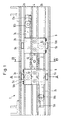
- Fig. 1 shows a rail of a cable guide of a hoist, the one is not shown in a frame rotatably mounted winch drum, in the Opposed rope grooves are formed on the surface.
- the rail 1 has two extending in the longitudinal direction of the rail and parallel to each other in the direction of Rope strands seen in succession arranged tracks 2a, 2b, which are spaced and laterally open channels are formed and to guide two Guide elements 3 serve, the tracks 2a, 2b by a web 4 with each other are connected.
- the guide elements 3 serve to align one pair Ropes related to the assigned rope groove and are in the longitudinal direction of the Rail 1 can be moved parallel to the axis of rotation of the winch drum and are used by the windable or unwindable rope strands driven.
- Guide elements 3 each have a support roller which is freely rotatable at the top and bottom 5a, 5b with a vertical axis of rotation seen in the direction of the rope strands tracks 2a, 2b arranged one behind the other are supported.
- a cable guide channel carrier 6 with a trained cable guide channel each attached to the guide element 3.
- the two guide elements 3 are each rigidly connected to a coupling longitudinal member 7a, 7b, the Coupling longitudinal members 7a, 7b as racks with the middle of the rails Teeth are formed.
- the two are Coupling longitudinal members 7a, 7b via a gearwheel freely rotatably mounted in the rail 1 8 interconnected, the pin 10 (Fig.
- Each coupling longitudinal member 7a, 7b is freely rotatable at the ends via horizontally stored impellers 10a, 10b in the track 2a or 2b, that is to two wide apart points, supported.
- each coupling side member is 7a, 7b on the guide element 3a or 3b via a vertically freely rotatable Support roller 11a or 11b movable in the track 2a or 2b in the longitudinal direction of the rail guided and supported.
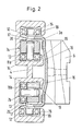
- Fig. 2 shows a cross section along section line A-A of Fig. 1.
- tracks 2a, 2b in the cross-sectional base support surfaces 12, 13th and form support surfaces 14 on the side surfaces.
- tracks 2a, 2b are included Holding elements provided, the vertically arranged support surfaces 18, 19 and horizontally arranged treads 20 which all run in the longitudinal direction of the rails. All the wheels 10a, 10b and all the support rollers 5a, 5b, 11a, 11b of the support surfaces 12, 13, 14, 18, 19, 20 both supported and guided. 2 is the web 4, which connects the two tracks 2a, 2b, can be clearly seen.
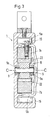
- FIG. 3 shows the cross section of the rail 1 in the region of the gear 8; so is in Fig. 3 in particular the interaction of the gear 8 with the as Rack-shaped coupling longitudinal members 7a, 7b can be removed.
- the gear 8 is freely rotatable with the pin 9 of the axis of rotation with radial play 21 in one in the Rail 1 provided hole used.
- the teeth 22 of the gear 8 grip at the top and bottom of the rack of the coupling side member 7a and 7b, whereby the racks are fixed to each other in their horizontal position.
- On Longitudinal section of the rail along the section line C - C according to FIG. 3 is in FIG. 4 played.
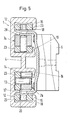
- Fig. 5 shows a cross section through the rail 1 along the section line A - A to Fig. 1 in an alternative embodiment, with all the wheels 10a, 10b as well all support rollers 5a, 5b, 11a, 11b by sliding elements 23 with a square Cross section are replaced; of course it is also possible to use the wheels and Only partially replace support rollers with sliding elements.
- the guide elements 3a, 3b by means of the support surfaces 12, 13, 14, 18, 19, 20 guided and supported, the sliding elements 23 when the Slide guide elements 3a, 3b along these support surfaces.
Landscapes
- Engineering & Computer Science (AREA)
- Mechanical Engineering (AREA)
- Types And Forms Of Lifts (AREA)
- Lift-Guide Devices, And Elevator Ropes And Cables (AREA)
- Transmission Devices (AREA)
- Movable Scaffolding (AREA)
- Emergency Lowering Means (AREA)
- Carriers, Traveling Bodies, And Overhead Traveling Cranes (AREA)
Claims (7)
- Guidage de câble pour un treuil, en particulier pour un treuil de levage, comportant un tambour de treuil monté à rotation dans un bâti et comportant des gorges de câble à marche contraire, des éléments de guidage (3) déplaçables sur au moins un rail (1) parallèlement à l'axe de rotation du tambour de treuil, prévus pour aligner au moins une paire de brins de câble avec des gorges de câble associées, reliés entre eux à marche contraire par des moyens de couplage, et entraínables par les brins de câble enroulables et déroulables, le rail (1) comportant au moins deux pistes s'étendant dans la direction longitudinale du rail et agencées en parallèle et l'une derrière l'autre par référence à la direction des brins de câble, pistes dans lesquelles les éléments de guidage (3) sont respectivement guidés et soutenus, les moyens de couplage comportant des longerons de couplage (7a, 7b), mobiles dans des sens opposés par référence à la direction longitudinale du rail, qui sont guidés respectivement dans l'une des pistes (2a, 2b) et qui sont soutenus le long de la piste (2a, 2b) en au moins deux points distants et chaque longeron de couplage (7a, 7b) étant relié à l'un des éléments de guidage (3a resp. 3b),
caractérisé en ce que
chaque longeron de couplage (7a, 7b) est soutenu respectivement dans la piste (2a, 2b) dans la région des extrémités du longeron de couplage par des roues porteuses (10a, 10b) montées horizontalement de façon à pouvoir tourner librement, est guidé à l'extrémité du longeron de couplage opposée à l'élément de guidage (3a, 3b) dans la piste (2a, 2b) par au moins un galet de support monté verticalement de façon à pouvoir tourner librement et est relié rigidement à l'un des éléments de guidage (3a resp. 3b). - Guidage de câble selon la revendication 1, caractérisé en ce que les longerons de couplage (7a, 7b) sont conformés en crémaillères dans lesquelles s'engage une roue dentée (8) montée de façon à pouvoir tourner librement dans le rail (1) et reliant les longerons de couplage (7a, 7b).
- Guidage de câble selon l'une des revendications 1 à 2, caractérisé en ce que chaque élément de guidage (3a, 3b) est soutenu respectivement au moyen de deux galets de support (11a, 11b) agencés sur l'élément de guidage (3a, 3b) dans les pistes (2a, 2b) agencées l'une derrière l'autre par référence à la direction des brins de câble.
- Guidage de câble selon l'une des revendications 1 à 3, caractérisé en ce que les pistes (2a, 2b) forment des surfaces d'appui (12, 13, 14) au fond de la section et/ou sur les faces latérales.
- Guidage de câble selon l'une des revendications 1 à 4, caractérisé en ce que les pistes (2a, 2b) sont dotées d'éléments de retenue (15, 16, 17) qui forment des surfaces de roulement (18, 19) et/ou des surfaces d'appui agencées verticalement et s'étendant dans la direction longitudinale du rail et des surfaces de roulement (20) et/ou des surfaces d'appui agencées horizontalement et s'étendant dans la direction longitudinale du rail.
- Guidage de câble selon l'une des revendications 1 à 5, caractérisé en ce que les roues porteuses (10a, 10b) et les galets de support (11a, 11b) sont en partie remplacés par des éléments coulissants (23).
- Guidage de câble selon l'une des revendications 1 à 6, caractérisé en ce que les dents (9) de la roue dentée (8) peuvent être insérées avec un jeu radial dans une ouverture ménagée dans le rail (1) à peu près à chaque position des longerons de couplage (7a, 7b) agencées dans les pistes.
Applications Claiming Priority (2)
| Application Number | Priority Date | Filing Date | Title |
|---|---|---|---|
| DE19617098A DE19617098C1 (de) | 1996-04-19 | 1996-04-19 | Seilführung für ein Windwerk |
| DE19617098 | 1996-04-19 |
Publications (3)
| Publication Number | Publication Date |
|---|---|
| EP0802152A2 EP0802152A2 (fr) | 1997-10-22 |
| EP0802152A3 EP0802152A3 (fr) | 1998-12-09 |
| EP0802152B1 true EP0802152B1 (fr) | 2003-06-11 |
Family
ID=7792780
Family Applications (1)
| Application Number | Title | Priority Date | Filing Date |
|---|---|---|---|
| EP97250121A Expired - Lifetime EP0802152B1 (fr) | 1996-04-19 | 1997-04-16 | Guidage de câble pour un treuil |
Country Status (5)
| Country | Link |
|---|---|
| US (1) | US5829737A (fr) |
| EP (1) | EP0802152B1 (fr) |
| JP (1) | JPH1036083A (fr) |
| KR (1) | KR970069864A (fr) |
| DE (2) | DE19617098C1 (fr) |
Families Citing this family (23)
| Publication number | Priority date | Publication date | Assignee | Title |
|---|---|---|---|---|
| FI110863B (fi) * | 2000-01-14 | 2003-04-15 | Kci Kone Cranes Int Oy | Köysitelan aksiaalituenta nostolaitteessa |
| KR100431792B1 (ko) * | 2000-12-13 | 2004-05-17 | 주식회사 포스코 | 하역기 와이어 권취 드럼의 와이어 유도장치 |
| WO2003091147A1 (fr) * | 2002-04-23 | 2003-11-06 | Matsushita Electric Works, Ltd. | Ascenseur |
| US7234685B2 (en) * | 2004-12-15 | 2007-06-26 | Britten Paul J | Apparatus for raising and lowering a banner |
| US7343958B1 (en) | 2005-04-04 | 2008-03-18 | Amarr Company | Overhead door lift system |
| MX2008013313A (es) * | 2006-04-28 | 2009-03-06 | Electronic Theatre Controls | Ensamble, sistema y metodo elevador. |
| BRPI0814747A2 (pt) * | 2007-08-24 | 2015-03-03 | Heerema Marine Contractors Nl | Dispositivo de deslocamento axial a ser usado em conjunto com um guincho rotativo, sistema de extensão de linha e método para extensão de uma linha. |
| RU2492904C2 (ru) * | 2007-11-08 | 2013-09-20 | Электроник Тиэте Контролз, Инк. | Системы подъемного узла и способы |
| US9248999B2 (en) * | 2009-09-25 | 2016-02-02 | Harry Xydias | Level wind arm for a winch assembly |
| EP2910514B1 (fr) | 2009-11-18 | 2016-10-19 | Electronic Theatre Controls, Inc. | Systèmes et procédés d'assemblage d'ascenseurs |
| US9127492B2 (en) | 2011-08-23 | 2015-09-08 | Raynor Mfg. Co. | Cable drum construction of door lift mechanism for multiple horizontal panel garage door with disproportionally heavy top portion |
| US20130230378A1 (en) * | 2011-11-22 | 2013-09-05 | Tait Towers Manufacturing, LLC | Winch apparatus |
| US10183850B2 (en) | 2012-12-21 | 2019-01-22 | Electronic Theatre Controls, Inc. | Compact hoist system |
| WO2015077822A1 (fr) * | 2013-11-27 | 2015-06-04 | Stress Free Marine Pty Ltd | Ensemble treuil amélioré et ensemble guide de corde de traction |
| US9963327B2 (en) * | 2015-05-18 | 2018-05-08 | Flexcrane, Inc. | Frustoconical drum winch for lifting loads with hook reduced approximation lifting height |
| CN105712230A (zh) * | 2016-04-17 | 2016-06-29 | 昆山克鲁克机电设备有限公司 | 起重机电动葫芦排绳装置 |
| CN106219424A (zh) * | 2016-07-30 | 2016-12-14 | 河南卫华机械工程研究院有限公司 | 一种多双联卷筒钢丝绳导向装置 |
| FI20175743A1 (fi) | 2017-08-21 | 2019-02-22 | Konecranes Global Oy | Köydenohjauslaite ja menetelmä köyden ohjaamiseksi |
| CN107963564A (zh) * | 2017-12-26 | 2018-04-27 | 王变芝 | 一种起重机用钢丝绳收卷防缠绕装置 |
| US10857015B2 (en) * | 2018-03-21 | 2020-12-08 | Medtronic Vascular, Inc. | Variable speed retraction mechanism delivery system and method |
| FI128653B (fi) | 2019-03-29 | 2020-09-30 | Konecranes Global Oy | Köysinostimen köydenohjauslaite |
| CN110304565B (zh) * | 2019-04-23 | 2021-02-19 | 扬州欧谱机械制造有限公司 | 一种用于煤矿开采的缆绳卷绕整齐的耐用型绞车 |
| CN112061939A (zh) * | 2020-09-23 | 2020-12-11 | 奥峰电梯有限公司 | 一种电梯控制驱动系统 |
Family Cites Families (12)
| Publication number | Priority date | Publication date | Assignee | Title |
|---|---|---|---|---|
| US1524198A (en) * | 1924-01-17 | 1925-01-27 | Morgan Engineering Co | Safety device for traveling cranes and the like |
| US2238398A (en) * | 1937-05-22 | 1941-04-15 | John E Reed | Line spooler |
| US2347885A (en) * | 1941-11-14 | 1944-05-02 | Charles S Crickmer | Wire line guide |
| FR1006645A (fr) * | 1947-12-29 | 1952-04-25 | Anciens Ets Brissonneau & Lotz | Guide-câble pour treuils |
| DE800325C (de) * | 1948-10-02 | 1950-10-30 | Achgelis Soehne A G M | Seilfuehrungsvorrichtung fuer Fischnetzwinden |
| US2738143A (en) * | 1955-04-07 | 1956-03-13 | Clifford B Hannay & Son Inc | Hose reel |
| US2984455A (en) * | 1957-08-06 | 1961-05-16 | California Research Corp | Multiple-cable tensioning device |
| US3215405A (en) * | 1962-11-06 | 1965-11-02 | Breeze Corp | Fleet angle control device |
| US3226090A (en) * | 1963-06-18 | 1965-12-28 | Aircraft Armaments Inc | Materials handling arrangement |
| CH579194A5 (fr) * | 1971-06-14 | 1976-08-31 | Mannesmann Leichtbau Gmbh | |
| FR2190641B1 (fr) * | 1972-06-26 | 1976-01-16 | Aerazur Constr Aeronaut | |
| DE4241655C1 (de) * | 1992-12-04 | 1994-04-21 | Mannesmann Ag | Seilführung für ein Windwerk, insbesondere ein Hubwerk |
-
1996
- 1996-04-19 DE DE19617098A patent/DE19617098C1/de not_active Expired - Fee Related
-
1997
- 1997-04-08 KR KR1019970012857A patent/KR970069864A/ko not_active Ceased
- 1997-04-08 US US08/833,392 patent/US5829737A/en not_active Expired - Lifetime
- 1997-04-14 JP JP9111981A patent/JPH1036083A/ja active Pending
- 1997-04-16 EP EP97250121A patent/EP0802152B1/fr not_active Expired - Lifetime
- 1997-04-16 DE DE59710247T patent/DE59710247D1/de not_active Expired - Lifetime
Also Published As
| Publication number | Publication date |
|---|---|
| KR970069864A (ko) | 1997-11-07 |
| EP0802152A3 (fr) | 1998-12-09 |
| US5829737A (en) | 1998-11-03 |
| JPH1036083A (ja) | 1998-02-10 |
| DE19617098C1 (de) | 1997-11-27 |
| EP0802152A2 (fr) | 1997-10-22 |
| DE59710247D1 (de) | 2003-07-17 |
Similar Documents
| Publication | Publication Date | Title |
|---|---|---|
| EP0802152B1 (fr) | Guidage de câble pour un treuil | |
| EP0080038B1 (fr) | Flèche télescopique, en particulier pour ascenseurs inclinés | |
| DE3104740A1 (de) | Foerder- und/oder sortiereinrichtung, zugeordneter wagen bzw. schlitten und diese einrichtung und derartige wagen bzw. schlitten enthaltende anlage | |
| DE19651948C1 (de) | Karusselltür | |
| DE19732451C2 (de) | Seilanordnung zur Aufhängung eines Anschlagmittels an einem Hubwerk, insbesondere für Laufkrane oder Laufkatzen | |
| WO1998050657A1 (fr) | Mecanisme de roulement pour un rail de guidage avec une cloison ou un autre element comparable suspendu au mecanisme de roulement | |
| EP0223007B1 (fr) | Porte coulissante autoporteuse | |
| EP0021386A1 (fr) | Elément de construction réglable en longueur | |
| DE202012008218U1 (de) | Kabelwagen | |
| AT407379B (de) | Seilführung für ein windwerk, insbesondere ein hubwerk | |
| DE1474967B1 (de) | Energiefuehrungskette zum Fuehren der Versorgungsleitungen eines beweglichen Verbrauchers | |
| EP2018338B1 (fr) | Chariot roulant pour des dispositifs de levage | |
| DE668060C (de) | Zwei- oder mehrfluegeliges Faltschiebetor | |
| DE2532400A1 (de) | Bewegbare begrenzungswand fuer ein fahrzeug | |
| DE2062198C3 (de) | Rollenbock für eine durch ein Zugseil betriebene Bahn für den Bergbau | |
| DE1167311B (de) | Registratur mit paternosterartig umlaufenden Traegern zur Aufnahme von Schriftgut | |
| DE2502147C2 (de) | Hochbaukran insbesondere mit Laufkatzenausleger | |
| EP0187976A2 (fr) | Dispositif de verrouillage pour éléments télescopiques de monte-charge | |
| DE10137257C2 (de) | Fahrschachttür | |
| DE3006611C2 (de) | Antriebsmechanismus für einen Auslegerkran | |
| DE503000C (de) | Schiebetor fuer grosse Hallen | |
| DE3525025A1 (de) | Fuehrung fuer eine befahreinrichtung eines bauwerkes | |
| DE1509476A1 (de) | Schiebewand | |
| DE2337892C2 (de) | Arbeitsgerüst mit heb- und senkbarer Arbeitsbühne | |
| EP4091970A1 (fr) | Dispositif de levage de charges |
Legal Events
| Date | Code | Title | Description |
|---|---|---|---|
| PUAI | Public reference made under article 153(3) epc to a published international application that has entered the european phase |
Free format text: ORIGINAL CODE: 0009012 |
|
| AK | Designated contracting states |
Kind code of ref document: A2 Designated state(s): DE FR GB IT |
|
| PUAL | Search report despatched |
Free format text: ORIGINAL CODE: 0009013 |
|
| AK | Designated contracting states |
Kind code of ref document: A3 Designated state(s): DE FR GB IT |
|
| 17P | Request for examination filed |
Effective date: 19990527 |
|
| 17Q | First examination report despatched |
Effective date: 20010925 |
|
| GRAH | Despatch of communication of intention to grant a patent |
Free format text: ORIGINAL CODE: EPIDOS IGRA |
|
| GRAH | Despatch of communication of intention to grant a patent |
Free format text: ORIGINAL CODE: EPIDOS IGRA |
|
| GRAA | (expected) grant |
Free format text: ORIGINAL CODE: 0009210 |
|
| RAP1 | Party data changed (applicant data changed or rights of an application transferred) |
Owner name: DEMAG CRANES & COMPONENTS GMBH |
|
| AK | Designated contracting states |
Designated state(s): DE FR GB IT |
|
| REG | Reference to a national code |
Ref country code: GB Ref legal event code: FG4D Free format text: NOT ENGLISH |
|
| REF | Corresponds to: |
Ref document number: 59710247 Country of ref document: DE Date of ref document: 20030717 Kind code of ref document: P |
|
| GBT | Gb: translation of ep patent filed (gb section 77(6)(a)/1977) |
Effective date: 20031027 |
|
| ET | Fr: translation filed | ||
| PLBE | No opposition filed within time limit |
Free format text: ORIGINAL CODE: 0009261 |
|
| STAA | Information on the status of an ep patent application or granted ep patent |
Free format text: STATUS: NO OPPOSITION FILED WITHIN TIME LIMIT |
|
| 26N | No opposition filed |
Effective date: 20040312 |
|
| PGFP | Annual fee paid to national office [announced via postgrant information from national office to epo] |
Ref country code: DE Payment date: 20130419 Year of fee payment: 17 Ref country code: GB Payment date: 20130418 Year of fee payment: 17 |
|
| PGFP | Annual fee paid to national office [announced via postgrant information from national office to epo] |
Ref country code: FR Payment date: 20130515 Year of fee payment: 17 Ref country code: IT Payment date: 20130424 Year of fee payment: 17 |
|
| REG | Reference to a national code |
Ref country code: DE Ref legal event code: R119 Ref document number: 59710247 Country of ref document: DE |
|
| GBPC | Gb: european patent ceased through non-payment of renewal fee |
Effective date: 20140416 |
|
| REG | Reference to a national code |
Ref country code: FR Ref legal event code: ST Effective date: 20141231 |
|
| REG | Reference to a national code |
Ref country code: DE Ref legal event code: R119 Ref document number: 59710247 Country of ref document: DE Effective date: 20141101 |
|
| PG25 | Lapsed in a contracting state [announced via postgrant information from national office to epo] |
Ref country code: DE Free format text: LAPSE BECAUSE OF NON-PAYMENT OF DUE FEES Effective date: 20141101 Ref country code: GB Free format text: LAPSE BECAUSE OF NON-PAYMENT OF DUE FEES Effective date: 20140416 |
|
| PG25 | Lapsed in a contracting state [announced via postgrant information from national office to epo] |
Ref country code: FR Free format text: LAPSE BECAUSE OF NON-PAYMENT OF DUE FEES Effective date: 20140430 |
|
| PG25 | Lapsed in a contracting state [announced via postgrant information from national office to epo] |
Ref country code: IT Free format text: LAPSE BECAUSE OF NON-PAYMENT OF DUE FEES Effective date: 20140416 |