EP0803613B1 - Méthode pour réaliser un mur dans le sol - Google Patents
Méthode pour réaliser un mur dans le sol Download PDFInfo
- Publication number
- EP0803613B1 EP0803613B1 EP97106631A EP97106631A EP0803613B1 EP 0803613 B1 EP0803613 B1 EP 0803613B1 EP 97106631 A EP97106631 A EP 97106631A EP 97106631 A EP97106631 A EP 97106631A EP 0803613 B1 EP0803613 B1 EP 0803613B1
- Authority
- EP
- European Patent Office
- Prior art keywords
- lining plate
- plate
- ground
- shell
- support
- Prior art date
- Legal status (The legal status is an assumption and is not a legal conclusion. Google has not performed a legal analysis and makes no representation as to the accuracy of the status listed.)
- Expired - Lifetime
Links
- 238000000034 method Methods 0.000 title claims description 33
- 239000002689 soil Substances 0.000 title description 16
- 238000005520 cutting process Methods 0.000 claims abstract description 20
- 230000002787 reinforcement Effects 0.000 claims abstract description 19
- 238000009412 basement excavation Methods 0.000 claims description 29
- 238000010276 construction Methods 0.000 claims description 19
- 239000004567 concrete Substances 0.000 claims description 16
- 238000009415 formwork Methods 0.000 claims description 6
- 239000011150 reinforced concrete Substances 0.000 claims description 4
- 230000000149 penetrating effect Effects 0.000 claims 1
- 238000009416 shuttering Methods 0.000 abstract 1
- 238000007789 sealing Methods 0.000 description 8
- 229910000831 Steel Inorganic materials 0.000 description 4
- 239000010959 steel Substances 0.000 description 4
- 230000006735 deficit Effects 0.000 description 2
- 239000000463 material Substances 0.000 description 2
- 230000035515 penetration Effects 0.000 description 2
- 239000007787 solid Substances 0.000 description 2
- 230000007704 transition Effects 0.000 description 2
- 241001474791 Proboscis Species 0.000 description 1
- 102000001999 Transcription Factor Pit-1 Human genes 0.000 description 1
- 108010040742 Transcription Factor Pit-1 Proteins 0.000 description 1
- 230000001154 acute effect Effects 0.000 description 1
- 230000002411 adverse Effects 0.000 description 1
- 230000015572 biosynthetic process Effects 0.000 description 1
- 238000006073 displacement reaction Methods 0.000 description 1
- 238000005516 engineering process Methods 0.000 description 1
- 230000002349 favourable effect Effects 0.000 description 1
- 239000003673 groundwater Substances 0.000 description 1
- 230000001771 impaired effect Effects 0.000 description 1
- 239000010410 layer Substances 0.000 description 1
- 238000004519 manufacturing process Methods 0.000 description 1
- 238000005096 rolling process Methods 0.000 description 1
- 239000003566 sealing material Substances 0.000 description 1
- 239000002356 single layer Substances 0.000 description 1
Images
Classifications
-
- E—FIXED CONSTRUCTIONS
- E02—HYDRAULIC ENGINEERING; FOUNDATIONS; SOIL SHIFTING
- E02D—FOUNDATIONS; EXCAVATIONS; EMBANKMENTS; UNDERGROUND OR UNDERWATER STRUCTURES
- E02D17/00—Excavations; Bordering of excavations; Making embankments
- E02D17/02—Foundation pits
- E02D17/04—Bordering surfacing or stiffening the sides of foundation pits
-
- E—FIXED CONSTRUCTIONS
- E04—BUILDING
- E04B—GENERAL BUILDING CONSTRUCTIONS; WALLS, e.g. PARTITIONS; ROOFS; FLOORS; CEILINGS; INSULATION OR OTHER PROTECTION OF BUILDINGS
- E04B2/00—Walls, e.g. partitions, for buildings; Wall construction with regard to insulation; Connections specially adapted to walls
- E04B2/84—Walls made by casting, pouring, or tamping in situ
- E04B2/86—Walls made by casting, pouring, or tamping in situ made in permanent forms
- E04B2/8611—Walls made by casting, pouring, or tamping in situ made in permanent forms with spacers being embedded in at least one form leaf
Definitions
- the invention relates to a method for erecting a wall in a floor as well a shoring plate for performing this procedure.
- DE 17 84 325 A1 describes a method for securing building pits by means of profiled beams and prefabricated plates known. First, H-shaped profile beams placed in the ground and then the prefabricated panels between the flanges of the profile beams. In the course of excavation of the pit At the bottom, the prefabricated panels slide through the flanges of the profile beams down until the plates have reached the desired depth.
- This method has the disadvantage that the plates are brought down very carefully without jamming be otherwise the risk of wedging the plates between the profile beams, which in turn breaks off the panel edges can lead.
- the profile beams partially protrude over the prefabricated panels addition, so that the wall is not built directly on a property boundary can, without adversely affecting the neighboring property.
- AU 90822/82 B describes a method for erecting a wall in a floor known.
- H-beams are first driven into the ground, that serve as supports for a shoring panel.
- the shoring plate is attached to this Supports slidably supported, with the ground dug on the side of the supports becomes. In this way, the sheeting board is sunk until it reaches the desired depth has reached. Then a foundation plate and possibly a cover plate is attached to the Concrete plate concreted on.
- this known method has the disadvantage that the shoring plate is blunt on its underside, so that it is particularly in hard soil penetrates poorly.
- a solid shoring plate which is pointed on the underside is trained. It has a tongue and groove profile on the sides, which is used for connection the side-by-side shoring plates.
- This shoring plate is therefore essentially only for supporting embankments suitable where connecting means between different heights Shoring boards a firm bond can be achieved.
- the invention has for its object a method for erecting a wall to be indicated in a soil in which the adjacent soil affects as little as possible and with which a firm association of the wall to be erected with a Plate or a foundation plate is reached. Furthermore, a shoring plate should be created that is suitable for performing this method.
- the pit is opposite Soil supported by the shoring plate during excavation of the construction pit.
- settlement of the ground is prevented when the excavation pit is excavated.
- the Shoring plate is preferably set up vertically.
- the shoring plate forms an acute angle with the vertical, to make an inclined wall.
- the shoring plate is preferably made of reinforced concrete, so that it at least is able to absorb part of the required load capacity. This method is particularly advantageous when the neighboring floor if possible should not be disturbed. This is particularly the case if the Wall should be built directly on a property boundary as it is often difficult and it is expensive to get permission from the neighbor to impair the property receive. In order to ensure an exact alignment of the shoring plate, at least set a prop in the ground.
- the shoring plate can be attached to this Support the sinking by sliding or rolling.
- the lateral ground pressure is in this Case advantageously taken from the support, so that subsidence in the surrounding Soil area are excluded even under unfavorable soil conditions.
- a reinforcement of the shoring plate is used bent in the horizontal direction. This clamping reinforcement ensures further Course of the procedure for a firm connection of a concrete floor to be erected On Wall.
- a corresponding clamping reinforcement can also be used Height can be used for the construction of ceiling or false ceilings.
- the construction work is particularly simple if, according to claim 3, the support into the floor below the bottom edge of the wall. In this case the lower end of the support in each section of lowering the shoring plate set in the ground, so that further support measures during dredging are unnecessary.
- the support could be through ground anchors be braced, the floor facing away from the excavation pit and thus in the adjacent one Property would have to be anchored.
- the support by a horizontal strut against the side Support ground pressure. This allows all construction work in the area within the excavation pit be carried out so that the adjacent ground in no way is affected. This method can therefore also be used advantageously in those cases use in which the wall is to be erected directly on a property boundary, the neighboring property does not tolerate any impairment of its property.
- an excavator mattress supported in the excavation pit is proposed to be provided as a flat counter bearing of the strut. This distributes the from the strut exerted pressure on the floor over a large area, so that a stable Support of the strut is guaranteed.
- the shoring plate is double-skinned and is filled with concrete after concreting a foundation slab.
- the shoring plate is used in this case as lost formwork, so that the wall is special can be created quickly and therefore inexpensively.
- the interior the shoring slab and the foundation slab are concreted wet in wet. This results in a homogeneous concrete structure, so that the wall together with the foundation slab results in a waterproof shell. This is particularly true in flood prone areas Areas or building pits close to the groundwater Meaning.
- the use of sealing tapes for sealing the transition between the foundation plate and the wall can be dispensed with.
- the lining plate according to claim 12 has been used to carry out this method proven. It has a multi-layer design, the cavity of the shoring panel preferably is poured out with concrete. This advantageously allows use the sheeting as lost formwork and results in a particularly inexpensive Creation of the wall. Especially when placing several shoring panels together In this case, the subsequent concrete filling creates an intimate one Bond between the individual shoring panels.
- a shell of the shoring plate, preferably the one facing the construction pit is on the underside opposite the counter shell shortened. This makes it easier to remove the soil when sinking the shoring plate because only the counter shell cuts and penetrates the floor.
- the shoring plate according to claim 13 is also multi-shell and has a narrow edge on the underside. This edge cuts when sinking in the ground, so that the weight of the shoring plate for Sinking is enough.
- the air-side shell is preferably shortened or the earth-side shell Shell formed with the narrow edge. This facilitates the sinking process the shoring plate.
- the shoring plate has a narrow longitudinal web, which Penetration of the shoring plate into the floor is easier.
- the reset blunt Surface prevents the sheeting plate from sinking too quickly and forms the connection surface the wall to be created on a base.
- An embodiment of the narrow edge as a cutting edge according to claim 16 allows one Sinking of the sheeting board even on harder soils because the cutting edge is very exerts great pressure on the floor and the weight of the shoring panel enough to penetrate the ground.
- the cutting edge can only be on the construction pit facing away from the bowl, if only this bowl in the ground penetrates.
- both shells can each have a cutting edge.
- the edges of both shells are preferably aligned so that they penetrate into the ground at the same time. To sink this shoring board, can also the bottom between the two shells can be removed. The shoring plate penetrates doing so like a caisson in the ground.
- the cutting edge is aligned with an outer surface of the shoring plate. This ensures that all of the cut soil is facing the excavation pit is pressed from where it can be easily removed. On the side facing away from the construction pit The floor is therefore not changed in any way on the side of the shoring plate.
- the reinforcements between the two shells ensure a solid structure and improve after concreting the space thus the load-bearing capacity of the wall.
- the shell facing the construction pit is opposite on all sides Counter shell shortened.
- there is between two shoring panels at every joint Access to the counter shell from the construction pit is possible.
- the resulting joint between the shoring plates on the counter shell can be easily seal with a sealing tape, for example.
- the by resetting the On the one hand a larger clearance due to the pit on the pit side allows reaching through and introduction of sealing material and can finally by a Seal simple formwork so that the interior of the shoring panel is then attached can be concreted.
- the upper setback of the shell is only necessary if a false ceiling is to be installed that is lower than the upper floor surface lies.
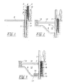
- FIG. 1 shows a shoring plate 1 consisting of a shell 2 and 3 on the excavation side a counter shell 3. Both shells 2, 3 are against each other by reinforcements 4 Kept clear.
- the pit 2 on the construction pit side is opposite the counter shell 3 shortened so that only the counter shell 3 rests on a floor 5.
- the counter shell 3 has a cutting edge 6 at its lower end, so that the sheeting panel 1 cuts into the floor 5 by its own weight.
- To hold the shoring plate 1 in a vertical position is a vertical support 7 with an H-shaped Cross section set in the bottom 5. To reduce the friction between the Shoring plate 1 and the support 7 are provided between these rollers 8.
- the method described below assumes that the one to be built Wall with a property boundary 9 should be created in alignment, whereby the adjacent property with its intended plantings 10 in none Way may be affected.
- the actual Depth depends on the local soil conditions and the depth of the to be created Excavation pit. Since the supports 7 struck only from the depth of the holes 11 or have to be shaken, the associated vibrations only arise at great depth. This will damage buildings on neighboring properties locked out.
- the shoring plate 1 After driving in the supports 7, the shoring plate 1 is lifted into the brought position shown, wherein between the shoring plate 1 and the support 7 Rollers 8 introduced to reduce friction and to protect the lining plate 1 become.
- the lining plate 1 then preferably penetrates exclusively through it own weight with its cutting edge 6 in the bottom 5. Then the excavation side Removed the floor so that the shoring plate 1 goes deeper into the floor 5 can cut.
- an excavator mattress 13 is used as a counter bearing in the excavation pit 12 provided for a strut 14 which holds the support 7 in position.
- the sinking the shoring panel 1 is increasing by further removing the bottom 5 from the deepening pit 12 continued.
- the base 15 preferably has a wedge shape. Alternatively, one could smaller plate can be used as a base 15. After the construction pit 12 in the area the shoring plate 1 is lifted, one becomes underside of the shoring plate 1 outstanding clamping reinforcement bent in the horizontal direction. Subsequently a foundation plate 17 is concreted onto the shoring plate 1. If not yet set Foundation plate 17 is the interior between the shells 2, 3 of the Concrete plate 1 concreted, so that there is a firm bond between the foundation plate 17 and the finished wall 18 results. After the concrete has hardened the strut 14 with the excavator mattress 13 is removed. The support 7 may vary Requirements either cut off at the level of the upper edge of the base 17 or be pulled out of the ground 5 again.
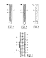
- FIG. 4 shows the shoring plate from FIG. 1, its shell 2 on the opposite side the counter shell 3 is shortened on the underside. Only the counter shell 3 has on the underside a cutting edge 6 aligned with its outer surface. Both shells 2, 3 are kept at a distance from one another by reinforcements 4.
- FIG. 5 shows an alternative shoring plate 1, the two shells 2, 3 of which are on the underside are of equal length. Both shells 2, 3 each have one with their Cutting surface 6 aligned on the outer surface. It can be used as a caisson be sunk into the ground. The floor material cut out in the process can be removed via a suction proboscis.
- FIG. 6 shows a single-shell design of a shoring plate 1, which itself is the one to be erected Wall forms.
- the lining plate 1 has a step 24 in the lower area, below which it is narrow. Your lower end is designed as a cutting edge 6, to ensure easy cutting into the ground. For soft floors can be dispensed with the cutting edge 6, especially if the weight of the Sheeting plate 1 already presses it into the ground. Sits level 24 while sinking especially in the case of soft floors, the weight is distributed the shoring plate 1 to a larger area, which causes a further sinking of the shoring plate 1 prevented. In this way, stage 24 prevents during the sinking the shoring plate 1 a too rapid and therefore undefined sinking.
- FIG. 7 shows two sheeting panels 1 abutting in series with their shells 2, 3 and the reinforcement 4.
- a joint 19 which is sealed with a sealing tape 20.
- this sealing tape 20 from the side of the excavation pit, that is to say from the left in FIG. 4, the shells 2 on the excavation side are shortened.
- the emerging between them Joint 21 is therefore designed to be correspondingly wider.
Landscapes
- Engineering & Computer Science (AREA)
- Civil Engineering (AREA)
- Mining & Mineral Resources (AREA)
- Architecture (AREA)
- Structural Engineering (AREA)
- General Life Sciences & Earth Sciences (AREA)
- General Engineering & Computer Science (AREA)
- Paleontology (AREA)
- Physics & Mathematics (AREA)
- Life Sciences & Earth Sciences (AREA)
- Electromagnetism (AREA)
- Conveying And Assembling Of Building Elements In Situ (AREA)
- Floor Finish (AREA)
- Forms Removed On Construction Sites Or Auxiliary Members Thereof (AREA)
- Underground Structures, Protecting, Testing And Restoring Foundations (AREA)
Claims (19)
- Procédé pour ériger des murs dans un sol (5), dans lequel on fixe au moins un support (7) dans le sol (5) côté fouille et on installe au moins une plaque de coffrage (1), qui est appuyée contre le support (7) pour supporter la pression latérale du sol, la plaque de coffrage (1) pénétrant dans le sol (5) en tranchant, étant successivement enfoncée, et le sol (5) étant déblayé d'un côté de la plaque de coffrage (1) jusqu'à ce que la profondeur d'enfoncement souhaitée soit atteinte, une armature de fixation (16) fixée dans la plaque de coffrage (1) étant dépliée dans le sens horizontal à partir de la plaque de coffrage (1) après que la profondeur d'enfoncement souhaitée a été atteinte afin de raccorder une plaque de fondation (17) ou une plaque, et la plaque de coffrage (1) restant ensuite dans le sol (5) en tant qu'élément constituant du mur à ériger (18).
- Procédé selon la revendication 1, dans lequel le sol (5) est à chaque fois déblayé jusqu'à la profondeur de coupe de la plaque de coffrage (1).
- Procédé selon la revendication 1, dans lequel le support (7) est inséré dans le sol (5) côté fouille jusque sous le bord inférieur du mur à ériger (18).
- Procédé selon la revendication 3, dans lequel, pour insérer le support (7) dans le sol (5), on pratique un trou (11) descendant approximativement jusqu'à la semelle du mur à ériger (18), dans lequel trou le support (7) est placé et enfoncé ensuite plus profondément pour la fixation.
- Procédé selon la revendication 3 ou 4, dans lequel on installe au moins un galet (8) afin de réduire le frottement entre la plaque de coffrage (1) et le support (7).
- Procédé selon au moins l'une des revendications 3 à 5, dans lequel, alors que l'enfoncement avance, le support (7) est étayé par un étai horizontal (14) contre la pression latérale du sol.
- Procédé selon la revendication 6, dans lequel l'autre extrémité de l'étai (14) est supportée dans la fouille (12) par un sommier d'excavation (13).
- Procédé selon au moins l'une des revendications 1 et 5 à 7, dans lequel au moins une cale (15) empêchant la plaque de coffrage de continuer à descendre est insérée sous la plaque de coffrage (1) après que la profondeur d'enfoncement souhaitée a été atteinte.
- Procédé selon au moins l'une des revendications 1 à 8, dans lequel, après le dépliage de l'armature de fixation, une plaque de fondation (17) ou une plaque est bétonnée à l'extrémité inférieure de la plaque de coffrage (1) afin de stabiliser le mur à ériger (18).
- Procédé selon la revendication 9, dans lequel, après le bétonnage de la plaque de fondation (17) ou de la plaque, un intérieur (23) d'une plaque de coffrage (1) réalisée avec deux parois est rempli de béton, de préférence humide sur humide avec la plaque de fondation (17) ou la plaque.
- Procédé selon au moins l'une des revendications 1 à 10, dans lequel plusieurs plaques de coffrage (1) à double paroi sont enfoncées successivement en rang et/ou en angle et dont les espaces de séparation (21) sont ensuite étanchéifiés, après quoi l'intérieur (23) des plaques de coffrage (1) est rempli de béton.
- Plaque de coffrage pour ériger des murs (18) et en tant qu'élément constituant de murs (18) dans des fouilles de construction (12), comprenant deux parois (2, 3) en béton armé, caractérisée en ce que l'une des parois (2) est réalisée plus courte au moins dans le bas par rapport à la paroi opposée (3) et en ce qu'une armature de fixation (16) pouvant être dépliée est fixée sur la plaque de coffrage (1).
- Plaque de coffrage selon la revendication 12 ou le préambule de la revendication 12, caractérisée en ce qu'au moins l'une des parois (2, 3) présente une arête réalisée de manière étroite par rapport à son épaisseur et en ce qu'une armature de fixation (16) pouvant être dépliée est fixée sur la plaque de coffrage (1).
- Plaque de coffrage selon la revendication 12 ou 13, caractérisée en ce que la paroi (2) côté fouille est réalisée plus courte dans le bas par rapport à la paroi opposée (3), et/ou la paroi opposée (3) présente l'arête réalisée de manière étroite.
- Plaque de coffrage pour ériger des murs (18) et en tant qu'élément constituant de murs (18) dans des fouilles de construction (12), comprenant une paroi (2) en béton armé, caractérisée en ce que la plaque de coffrage (1) présente une traverse longitudinale étroite dans le bas, qui fait saillie par rapport à une surface terminale (24) sans tranchant, et en ce qu'une armature de fixation (16) pouvant être dépliée est fixée sur la plaque de coffrage (1).
- Plaque de coffrage selon au moins l'une des revendications 13 à 15, caractérisée en ce que l'arête étroite ou la traverse longitudinale est réalisée en tant que tranchant (6).
- Plaque de coffrage selon au moins l'une des revendications 14 à 16, caractérisée en ce que l'arête, la traverse longitudinale ou le tranchant (6) est aligné(e) sur une surface extérieure de la plaque de coffrage (1) détournée de la fouille de construction (12).
- Plaque de coffrage selon la revendication 13 ou 14, caractérisée en ce que les deux parois (2, 3) sont maintenues à distance l'une de l'autre de préférence par des armatures (4) et forment un coffrage perdu pour le mur à ériger (18).
- Plaque de coffrage selon la revendication 13 ou 14, caractérisée en ce que la paroi (2) tournée vers la fouille de construction (12) est réalisée plus courte de tous côtés par rapport à la paroi opposée (3).
Applications Claiming Priority (2)
| Application Number | Priority Date | Filing Date | Title |
|---|---|---|---|
| DE19616188 | 1996-04-23 | ||
| DE19616188A DE19616188C2 (de) | 1996-04-23 | 1996-04-23 | Verfahren zum Errichten einer Wand in einem Boden |
Publications (2)
| Publication Number | Publication Date |
|---|---|
| EP0803613A1 EP0803613A1 (fr) | 1997-10-29 |
| EP0803613B1 true EP0803613B1 (fr) | 1999-10-13 |
Family
ID=7792200
Family Applications (1)
| Application Number | Title | Priority Date | Filing Date |
|---|---|---|---|
| EP97106631A Expired - Lifetime EP0803613B1 (fr) | 1996-04-23 | 1997-04-22 | Méthode pour réaliser un mur dans le sol |
Country Status (3)
| Country | Link |
|---|---|
| EP (1) | EP0803613B1 (fr) |
| AT (1) | ATE185607T1 (fr) |
| DE (2) | DE19616188C2 (fr) |
Families Citing this family (10)
| Publication number | Priority date | Publication date | Assignee | Title |
|---|---|---|---|---|
| DE19732256C2 (de) * | 1997-07-26 | 2001-03-29 | Bilfinger Berger Bau | Verfahren zur Herstellung einer Kelleraußenwand |
| DE19754506A1 (de) * | 1997-12-09 | 1999-06-10 | Ross Kurt G | Pfeiler-Anker-Stützkonstruktion |
| EP1526220A1 (fr) * | 2003-10-23 | 2005-04-27 | Applied Geotechnical Engineering Limited | Dispositif servant a supporter dans pour la construction de batiment |
| DE102017101061A1 (de) | 2016-01-22 | 2017-07-27 | Hans Böck Gmbh & Co. | Vorrichtung zum Lösen eines Profilträgers mit einer Kulisse |
| DE202016100311U1 (de) | 2016-01-22 | 2016-02-05 | Hans Böck Gmbh & Co. | Stahlträger-Drückvorrichtung |
| DE202016104385U1 (de) | 2016-08-09 | 2016-11-15 | Hans Böck Gmbh & Co. | Wandelement |
| DE102016114771A1 (de) | 2016-08-09 | 2018-02-15 | Hans Böck Gmbh & Co. | Wandelement |
| CN109440774A (zh) * | 2018-12-27 | 2019-03-08 | 上海建工七建集团有限公司 | 一种基坑结构及其施工方法 |
| CN115110599B (zh) * | 2022-08-25 | 2022-11-11 | 山西路桥市政工程有限公司 | 一种深基坑自动排土施工工艺 |
| CN115949062B (zh) * | 2023-03-10 | 2023-06-02 | 中铁城建集团第一工程有限公司 | 一种细砂地质坑槽坡面预制件插入装置及施工方法 |
Family Cites Families (14)
| Publication number | Priority date | Publication date | Assignee | Title |
|---|---|---|---|---|
| US1175750A (en) * | 1915-01-13 | 1916-03-14 | Enno H August Habbert | Sleeve for shirts. |
| DE1956736U (de) * | 1966-07-08 | 1967-03-09 | Otto Hofmann | Vorgefertigtes, als bleibende schalung geeignetes armiertes wandbauelement. |
| DE1658878A1 (de) * | 1968-01-23 | 1970-11-26 | Georg Hubmann | Bauelementesatz zur Schalung von Waenden mit vorgefertigten Schalungsplatten aus Stahlbeton |
| DE1784325A1 (de) * | 1968-07-27 | 1971-08-05 | Thormann & Stiefel Ag Thosti | Verfahren zur Baugrubensicherung mittels Profiltraegern und vorgefertigten Platten aus Stahlbeton oder Spannbeton |
| DE1998231U (de) * | 1968-08-10 | 1968-12-12 | Rheinbau Gmbh | Wandelemente zum errichten von gebaueden und dergleichen |
| US3563044A (en) * | 1969-03-28 | 1971-02-16 | Pomeroy & Co Inc J H | Method for constructing stabilized construction wall in unstable footing |
| NL160356C (nl) * | 1973-02-10 | 1979-10-15 | Hudswell Morrice Ltd | Werkwijze voor het leggen van een pijpleiding in een greppel. |
| DE2323321C3 (de) * | 1973-05-09 | 1980-06-04 | Josef 5138 Heinsberg Krings | Verbauwand einer Grabenverbauvorrichtung |
| DE2830264C2 (de) * | 1978-07-10 | 1980-06-12 | Bilfinger + Berger Bauaktiengesellschaft, 6800 Mannheim | Verfahren zur Herstellung einer unmittelbar mit einem benachbarten Gebäude fluchtend in den Baugrund einzubringenden, selbsttragenden Betonwand |
| JPS56156323A (en) * | 1980-05-07 | 1981-12-03 | Hiroshi Ito | Simple soil sheathing work |
| DE3201601A1 (de) * | 1982-01-20 | 1983-07-28 | Günther 2000 Hamburg Spranger | Verfahren zum einbringen von spundwaenden o.dgl. in erdreich durch spuelung sowie bauelement zur durchfuehrung des verfahrens. |
| DE3210659A1 (de) * | 1982-03-23 | 1983-10-06 | Anton Dipl Ing Frank | Verbau, insbesondere fuer schalungen |
| DE3242364A1 (de) * | 1982-11-16 | 1984-05-17 | geb. Macheiner Monika 6741 Rohrbach Ehold | Bauteile fuer den hochbau |
| DE9012301U1 (de) * | 1990-08-27 | 1990-11-22 | Heß, Wilhelm, 5000 Köln | Verbauvorrichtung |
-
1996
- 1996-04-23 DE DE19616188A patent/DE19616188C2/de not_active Expired - Fee Related
-
1997
- 1997-04-22 AT AT97106631T patent/ATE185607T1/de not_active IP Right Cessation
- 1997-04-22 EP EP97106631A patent/EP0803613B1/fr not_active Expired - Lifetime
- 1997-04-22 DE DE59700543T patent/DE59700543D1/de not_active Expired - Lifetime
Also Published As
| Publication number | Publication date |
|---|---|
| DE19616188A1 (de) | 1997-11-13 |
| DE19616188C2 (de) | 1998-07-02 |
| ATE185607T1 (de) | 1999-10-15 |
| EP0803613A1 (fr) | 1997-10-29 |
| DE59700543D1 (de) | 1999-11-18 |
Similar Documents
| Publication | Publication Date | Title |
|---|---|---|
| DE69635549T2 (de) | Verfahren und vorrichtung zur errichtung von endlosen unterirdischen mauern | |
| EP0803613B1 (fr) | Méthode pour réaliser un mur dans le sol | |
| DE69804834T2 (de) | Bogenbauträgerstruktur | |
| DE3615601C1 (de) | Rohrtragbohle fuer eine kombinierte Spundwand | |
| EP2573276B1 (fr) | Élément de banche pour parois moulées | |
| DE3710822A1 (de) | Tiefbauwerk in grundwasserfuehrendem erdreich | |
| DE102018103201A1 (de) | Verbauvorrichtung | |
| DE202019100752U1 (de) | Verbauvorrichtung | |
| CN1088487C (zh) | 挡土墙的成形方法 | |
| DE60002318T2 (de) | Verfahren zur bildung eines wasserdichtes und die kriechgrenze steigernden abschnittes | |
| DE4119259A1 (de) | Verfahren zur herstellung von untergeschossen unter ein bestehendes gebaeude | |
| DE2917994C2 (de) | Verfahren zur Herstellung einer Baugrubenverbau- oder Stützwand aus Stahlbeton für Geländeeinschnitte | |
| KR200270268Y1 (ko) | 길이조절식 토류판 | |
| EP0474204B1 (fr) | Procédé pour compenser l'inclinaison de tours penchées | |
| DE19522150C1 (de) | Verfahren zur Erstellung einer Baugrube mit einer Grundwasserabsperrung | |
| EP1964978B1 (fr) | Procédé d'établissement d'une installation de quai et installation de quai | |
| WO2004044334A1 (fr) | Systeme de protection contre les hautes eaux | |
| DE102006019236B4 (de) | Verfahren und Vorrichtung für den Grabenverbau | |
| LU502198B1 (de) | Plattform zum Empfangen eines rechteckigen Vortriebsrohres | |
| DE102008054170B4 (de) | Deponiesohlenerschließung | |
| DE859877C (de) | Staumauer aus Stahlbeton | |
| DE2543997A1 (de) | Verfahren zum einpressen eines insbesondere rohrfoermigen baukoerpers in einen erddamm o.dgl. | |
| DE2942428A1 (de) | Verfahren zum ausbau von hafenanlagen o.dgl. | |
| DE3716750A1 (de) | Verfahren zum herstellen und niederbringen von gruendungsbauwerken | |
| EP1553230B1 (fr) | Méthode pour remettre en état des murs de soutènement |
Legal Events
| Date | Code | Title | Description |
|---|---|---|---|
| PUAI | Public reference made under article 153(3) epc to a published international application that has entered the european phase |
Free format text: ORIGINAL CODE: 0009012 |
|
| AK | Designated contracting states |
Kind code of ref document: A1 Designated state(s): AT CH DE FR GB IT LI NL |
|
| 17P | Request for examination filed |
Effective date: 19971205 |
|
| GRAG | Despatch of communication of intention to grant |
Free format text: ORIGINAL CODE: EPIDOS AGRA |
|
| GRAG | Despatch of communication of intention to grant |
Free format text: ORIGINAL CODE: EPIDOS AGRA |
|
| GRAH | Despatch of communication of intention to grant a patent |
Free format text: ORIGINAL CODE: EPIDOS IGRA |
|
| 17Q | First examination report despatched |
Effective date: 19990310 |
|
| GRAH | Despatch of communication of intention to grant a patent |
Free format text: ORIGINAL CODE: EPIDOS IGRA |
|
| GRAA | (expected) grant |
Free format text: ORIGINAL CODE: 0009210 |
|
| AK | Designated contracting states |
Kind code of ref document: B1 Designated state(s): AT CH DE FR GB IT LI NL |
|
| REF | Corresponds to: |
Ref document number: 185607 Country of ref document: AT Date of ref document: 19991015 Kind code of ref document: T |
|
| REG | Reference to a national code |
Ref country code: CH Ref legal event code: EP |
|
| GBT | Gb: translation of ep patent filed (gb section 77(6)(a)/1977) |
Effective date: 19991014 |
|
| ITF | It: translation for a ep patent filed | ||
| REG | Reference to a national code |
Ref country code: CH Ref legal event code: NV Representative=s name: TROESCH SCHEIDEGGER WERNER AG |
|
| REF | Corresponds to: |
Ref document number: 59700543 Country of ref document: DE Date of ref document: 19991118 |
|
| ET | Fr: translation filed | ||
| PLBE | No opposition filed within time limit |
Free format text: ORIGINAL CODE: 0009261 |
|
| STAA | Information on the status of an ep patent application or granted ep patent |
Free format text: STATUS: NO OPPOSITION FILED WITHIN TIME LIMIT |
|
| 26N | No opposition filed | ||
| REG | Reference to a national code |
Ref country code: GB Ref legal event code: IF02 |
|
| PGFP | Annual fee paid to national office [announced via postgrant information from national office to epo] |
Ref country code: NL Payment date: 20070430 Year of fee payment: 11 Ref country code: AT Payment date: 20070430 Year of fee payment: 11 |
|
| PGFP | Annual fee paid to national office [announced via postgrant information from national office to epo] |
Ref country code: CH Payment date: 20070619 Year of fee payment: 11 |
|
| PGFP | Annual fee paid to national office [announced via postgrant information from national office to epo] |
Ref country code: GB Payment date: 20070418 Year of fee payment: 11 |
|
| PGFP | Annual fee paid to national office [announced via postgrant information from national office to epo] |
Ref country code: IT Payment date: 20070615 Year of fee payment: 11 |
|
| PGFP | Annual fee paid to national office [announced via postgrant information from national office to epo] |
Ref country code: FR Payment date: 20070329 Year of fee payment: 11 |
|
| REG | Reference to a national code |
Ref country code: CH Ref legal event code: PL |
|
| GBPC | Gb: european patent ceased through non-payment of renewal fee |
Effective date: 20080422 |
|
| NLV4 | Nl: lapsed or anulled due to non-payment of the annual fee |
Effective date: 20081101 |
|
| PG25 | Lapsed in a contracting state [announced via postgrant information from national office to epo] |
Ref country code: NL Free format text: LAPSE BECAUSE OF NON-PAYMENT OF DUE FEES Effective date: 20081101 Ref country code: LI Free format text: LAPSE BECAUSE OF NON-PAYMENT OF DUE FEES Effective date: 20080430 Ref country code: CH Free format text: LAPSE BECAUSE OF NON-PAYMENT OF DUE FEES Effective date: 20080430 |
|
| REG | Reference to a national code |
Ref country code: FR Ref legal event code: ST Effective date: 20081231 |
|
| PG25 | Lapsed in a contracting state [announced via postgrant information from national office to epo] |
Ref country code: AT Free format text: LAPSE BECAUSE OF NON-PAYMENT OF DUE FEES Effective date: 20080422 |
|
| PG25 | Lapsed in a contracting state [announced via postgrant information from national office to epo] |
Ref country code: FR Free format text: LAPSE BECAUSE OF NON-PAYMENT OF DUE FEES Effective date: 20080430 |
|
| PG25 | Lapsed in a contracting state [announced via postgrant information from national office to epo] |
Ref country code: GB Free format text: LAPSE BECAUSE OF NON-PAYMENT OF DUE FEES Effective date: 20080422 |
|
| PG25 | Lapsed in a contracting state [announced via postgrant information from national office to epo] |
Ref country code: IT Free format text: LAPSE BECAUSE OF NON-PAYMENT OF DUE FEES Effective date: 20080422 |
|
| PGFP | Annual fee paid to national office [announced via postgrant information from national office to epo] |
Ref country code: DE Payment date: 20160621 Year of fee payment: 20 |
|
| REG | Reference to a national code |
Ref country code: DE Ref legal event code: R071 Ref document number: 59700543 Country of ref document: DE |