EP0803937A1 - Connecteur avec verrouillage d'inertie - Google Patents
Connecteur avec verrouillage d'inertie Download PDFInfo
- Publication number
- EP0803937A1 EP0803937A1 EP97107031A EP97107031A EP0803937A1 EP 0803937 A1 EP0803937 A1 EP 0803937A1 EP 97107031 A EP97107031 A EP 97107031A EP 97107031 A EP97107031 A EP 97107031A EP 0803937 A1 EP0803937 A1 EP 0803937A1
- Authority
- EP
- European Patent Office
- Prior art keywords
- resistance
- connector
- male
- movement
- contact
- Prior art date
- Legal status (The legal status is an assumption and is not a legal conclusion. Google has not performed a legal analysis and makes no representation as to the accuracy of the status listed.)
- Granted
Links
- 230000000295 complement effect Effects 0.000 description 3
- 238000003780 insertion Methods 0.000 description 3
- 230000037431 insertion Effects 0.000 description 3
- 230000004048 modification Effects 0.000 description 3
- 238000012986 modification Methods 0.000 description 3
- 230000013011 mating Effects 0.000 description 2
- 230000000694 effects Effects 0.000 description 1
Images


Classifications
-
- H—ELECTRICITY
- H01—ELECTRIC ELEMENTS
- H01R—ELECTRICALLY-CONDUCTIVE CONNECTIONS; STRUCTURAL ASSOCIATIONS OF A PLURALITY OF MUTUALLY-INSULATED ELECTRICAL CONNECTING ELEMENTS; COUPLING DEVICES; CURRENT COLLECTORS
- H01R13/00—Details of coupling devices of the kinds covered by groups H01R12/70 or H01R24/00 - H01R33/00
- H01R13/64—Means for preventing incorrect coupling
- H01R13/641—Means for preventing incorrect coupling by indicating incorrect coupling; by indicating correct or full engagement
-
- H—ELECTRICITY
- H01—ELECTRIC ELEMENTS
- H01R—ELECTRICALLY-CONDUCTIVE CONNECTIONS; STRUCTURAL ASSOCIATIONS OF A PLURALITY OF MUTUALLY-INSULATED ELECTRICAL CONNECTING ELEMENTS; COUPLING DEVICES; CURRENT COLLECTORS
- H01R13/00—Details of coupling devices of the kinds covered by groups H01R12/70 or H01R24/00 - H01R33/00
- H01R13/62—Means for facilitating engagement or disengagement of coupling parts or for holding them in engagement
- H01R13/627—Snap or like fastening
- H01R13/6271—Latching means integral with the housing
- H01R13/6272—Latching means integral with the housing comprising a single latching arm
-
- H—ELECTRICITY
- H01—ELECTRIC ELEMENTS
- H01R—ELECTRICALLY-CONDUCTIVE CONNECTIONS; STRUCTURAL ASSOCIATIONS OF A PLURALITY OF MUTUALLY-INSULATED ELECTRICAL CONNECTING ELEMENTS; COUPLING DEVICES; CURRENT COLLECTORS
- H01R13/00—Details of coupling devices of the kinds covered by groups H01R12/70 or H01R24/00 - H01R33/00
- H01R13/46—Bases; Cases
- H01R13/52—Dustproof, splashproof, drip-proof, waterproof, or flameproof cases
- H01R13/5219—Sealing means between coupling parts, e.g. interfacial seal
-
- H—ELECTRICITY
- H01—ELECTRIC ELEMENTS
- H01R—ELECTRICALLY-CONDUCTIVE CONNECTIONS; STRUCTURAL ASSOCIATIONS OF A PLURALITY OF MUTUALLY-INSULATED ELECTRICAL CONNECTING ELEMENTS; COUPLING DEVICES; CURRENT COLLECTORS
- H01R13/00—Details of coupling devices of the kinds covered by groups H01R12/70 or H01R24/00 - H01R33/00
- H01R13/66—Structural association with built-in electrical component
- H01R13/70—Structural association with built-in electrical component with built-in switch
- H01R13/703—Structural association with built-in electrical component with built-in switch operated by engagement or disengagement of coupling parts, e.g. dual-continuity coupling part
- H01R13/7031—Shorting, shunting or bussing of different terminals interrupted or effected on engagement of coupling part, e.g. for ESD protection, line continuity
- H01R13/7032—Shorting, shunting or bussing of different terminals interrupted or effected on engagement of coupling part, e.g. for ESD protection, line continuity making use of a separate bridging element directly cooperating with the terminals
Definitions
- the present Invention is directed to an improved form of inertia locking connector, in particular, a device which can be readily and reliably assembled.
- the present Invention is particular useful in the field of electrical connectors.
- an inertia locking mechanism is used. This generates an initial resistance to fitting which is greater than the fitting resistance between the terminals themselves. When the initial resistance is overcome, this resistance is quickly relaxed. This provides consistency of feel so that the operator can better judge when fitting is complete. Moreover, the momentum of the connector, which results from the release of the initial resistance, aids in completing the fitting operation.
- First connector 1 is provided with locking arm 2.
- Second connector 3 has corresponding engagement portion 4 located thereon.
- locking arm 2 rides up over engagement portion 4 until it is in contact with the rear face thereof, thus locking the two parts together.
- the fitting resistance is generated by the front of engagement portion 4 contacting the distal end of locking arm 2. When this is overridden, locking is complete.
- an object of the present Invention to provide a device for generating suitable fitting resistance which will give a consistent operating feel, even if the locking arm is unlocked. It is also an object of the present Invention to provide the foregoing without the necessity of changing the shape of the complementary connector.
- the present Invention is directed to male and female locking connectors with a detent on one connector and a locking element on the other.
- the locking element rides up over the detent during locking movement and drops down on the other side, thereby bearing against the rear face of the detent and locking the two connectors together.
- the locking element is disengaged from the detent, usually by pressing on the proximal end thereof.
- the resistant element bears against the resistance surface to generate the desired resistance to movement of the two connectors into their locking position.
- the resistance element has a leading end facing the leading edge of the resistance surface. They are advantageously located so that the leading edge and leading end contact each other during the fitting movement of the connectors before the locking element contacts the detent. Thus, the initial resistance is created and preferably released before the locking element reaches the detent. Thus, by pressing the two parts together, momentum is built up which will carry the locking element over the detent and into its proper locked position.
- the leading edge of the resistance surface may he slanted to allow the resistance element to ride thereover without damage to any of the components of the connectors.
- the leading edge is substantially transverse to the direction of fitting movement and the resistance element has a protuberance adjacent the distal end thereof. This protuberance extends in a transverse direction toward the resistance surface. Therefore, the leading edge contacts the resistance element at a point on the protuberance which is eccentric to the axis of the resistance element. As a result, pressure in the fitting direction causes the resistance element to bend and thereby slide over the leading edge.
- a pair of resistance elements in the form of upstanding generally planar ribs which are transversely spaced apart.
- the resistance element is a pair of elongated resistance arms transversely flexible and biased toward the ribs.
- the detent is located between the ribs and the locking arm is located between the resistance arms.
- female connector 20 is adapted to receive fitting portion 12 on housing 10 of mating connector 11.
- connector 11 On the surface thereof, connector 11 is provided with detent 14 with guide surface 15 and engagement surface 16.
- Male terminal 13 is located within fitting portion 12.
- Female connector 20 comprises housing 21 and hood 23.
- Female terminal 22 is located within the housing.
- Locking arm 25 is provided on one surface thereof and is complementary to detent 14.
- On either side of locking arm 25 are resistance arms 29.
- Each arm carries projection 30 which is provided with contact surface 31 and guide surface 32. Arms 29 are flexible in a direction transverse to the insertion direction and active space 24 is located between side walls 28 and resistance arms 29 for this purpose.
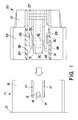
- engagement surface 16 is slanted, as shown in Figure 1, to facilitate disengagement of the connectors.
- engagement surface 16 can be vertical.
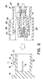
- the connectors are disengaged by pressing on pressing portion 27 which causes engagement projection 26 to move upwardly (as shown in Figure 2) so that it is no longer in contact with engagement surface 16.
- resistance arms 29 extend from the front of connector 20 toward the rear thereof.
- connection portion 12 of connector 11 is inserted into hood 23. Partial insertion is shown in Figure 3. As can be seen there, contact surfaces 31 are in contact with the leading edges of ribs 17. Further pressure is then exerted which causes resistance arms 29 to bend inwardly, thereby slanting contact surfaces 31. This causes resistance arms 29 to spread and ride up over the outside of ribs 17.
- the present Invention is capable of providing substantially increased fitting resistance as desired, without any need to modify either the height or the width thereof, thereby eliminating the need to redesign existing male connectors.
- the resistance arms flex in a direction parallel to the upper surface of the connector.
- flexure can take place perpendicularly to the upper surface with substantially the same effect. In that case, spaces 24 would be located between the upper surface and the resistance arms.
Landscapes
- Details Of Connecting Devices For Male And Female Coupling (AREA)
Applications Claiming Priority (3)
| Application Number | Priority Date | Filing Date | Title |
|---|---|---|---|
| JP10829096A JP3301522B2 (ja) | 1996-04-26 | 1996-04-26 | コネクタ |
| JP10829096 | 1996-04-26 | ||
| JP108290/96 | 1996-04-26 |
Publications (2)
| Publication Number | Publication Date |
|---|---|
| EP0803937A1 true EP0803937A1 (fr) | 1997-10-29 |
| EP0803937B1 EP0803937B1 (fr) | 2001-06-27 |
Family
ID=14480932
Family Applications (1)
| Application Number | Title | Priority Date | Filing Date |
|---|---|---|---|
| EP97107031A Expired - Lifetime EP0803937B1 (fr) | 1996-04-26 | 1997-04-28 | Connecteur avec verrouillage d'inertie |
Country Status (4)
| Country | Link |
|---|---|
| US (1) | US5876232A (fr) |
| EP (1) | EP0803937B1 (fr) |
| JP (1) | JP3301522B2 (fr) |
| DE (1) | DE69705352T2 (fr) |
Cited By (6)
| Publication number | Priority date | Publication date | Assignee | Title |
|---|---|---|---|---|
| EP0975061A3 (fr) * | 1998-07-23 | 2000-04-12 | Sumitomo Wiring Systems, Ltd. | Connecteur étanche à l'eau avec méchanisme de verrouillage d'inertie |
| EP1215772A3 (fr) * | 2000-12-12 | 2003-08-06 | J.S.T. Mfg. Co., Ltd. | Assemblage de connecteur avec verrouillage |
| DE10209076B4 (de) * | 2001-03-02 | 2013-03-14 | Sumitomo Wiring Systems, Ltd. | Verbinder mit Verriegelungsarm |
| EP3252876A1 (fr) * | 2016-06-01 | 2017-12-06 | Delphi Technologies, Inc. | Prise électrique avec fonction de codage |
| CN108511927A (zh) * | 2017-02-28 | 2018-09-07 | 欧姆龙株式会社 | 端子台 |
| DE102017123390A1 (de) * | 2017-10-09 | 2019-04-11 | Te Connectivity Germany Gmbh | Kontakteinrichtung und Kontaktsystem |
Families Citing this family (26)
| Publication number | Priority date | Publication date | Assignee | Title |
|---|---|---|---|---|
| JP3467185B2 (ja) * | 1998-04-08 | 2003-11-17 | 矢崎総業株式会社 | コネクタのロック機構 |
| DE19828636C2 (de) * | 1998-06-26 | 2000-07-06 | Framatome Connectors Int | Steckverbinder mit Schnappverschluß |
| JP3651311B2 (ja) * | 1999-05-26 | 2005-05-25 | ソニー株式会社 | 光コネクタ |
| US6364686B2 (en) * | 1999-11-30 | 2002-04-02 | Tyco Electronics Amp Gmbh | Electrical and/or optical connector with a latching arm |
| JP3648432B2 (ja) | 2000-05-25 | 2005-05-18 | 矢崎総業株式会社 | 慣性ロック式コネクタ |
| JP3840039B2 (ja) | 2000-06-01 | 2006-11-01 | 矢崎総業株式会社 | 慣性ロックコネクタ |
| JP3470888B2 (ja) * | 2000-06-21 | 2003-11-25 | タイコエレクトロニクスアンプ株式会社 | コネクタ組立体 |
| US6565383B1 (en) * | 2002-09-11 | 2003-05-20 | Hon Hai Precision Ind. Co., Ltd. | Electrical connector with locking member |
| US6585536B1 (en) * | 2002-09-11 | 2003-07-01 | Hon Hai Precision Ind. Co., Ltd. | Cable end connector with locking member |
| US6585537B1 (en) * | 2002-10-24 | 2003-07-01 | Hon Hai Precision Ind. Co., Ltd. | Cable end connector with locking member |
| US8109883B2 (en) | 2006-09-28 | 2012-02-07 | Tyco Healthcare Group Lp | Cable monitoring apparatus |
| US8668651B2 (en) | 2006-12-05 | 2014-03-11 | Covidien Lp | ECG lead set and ECG adapter system |
| JP2008270127A (ja) * | 2007-04-25 | 2008-11-06 | Sumitomo Wiring Syst Ltd | コネクタ |
| CA2646037C (fr) | 2007-12-11 | 2017-11-28 | Tyco Healthcare Group Lp | Connecteur d'electrode pour ecg |
| USD737979S1 (en) | 2008-12-09 | 2015-09-01 | Covidien Lp | ECG electrode connector |
| US8694080B2 (en) * | 2009-10-21 | 2014-04-08 | Covidien Lp | ECG lead system |
| CA2746944C (fr) | 2010-07-29 | 2018-09-25 | Tyco Healthcare Group Lp | Systeme adaptateur pour ecg et methode connexe |
| JP5674124B2 (ja) * | 2010-12-21 | 2015-02-25 | 矢崎総業株式会社 | コネクタハウジング |
| DK2734106T3 (da) | 2011-07-22 | 2020-01-06 | Kpr Us Llc | Ekg-elektrodekonnektor |
| US8634901B2 (en) | 2011-09-30 | 2014-01-21 | Covidien Lp | ECG leadwire system with noise suppression and related methods |
| WO2014149548A1 (fr) | 2013-03-15 | 2014-09-25 | Covidien Lp | Connecteur d'électrode à élément conducteur |
| US9408546B2 (en) | 2013-03-15 | 2016-08-09 | Covidien Lp | Radiolucent ECG electrode system |
| USD771818S1 (en) | 2013-03-15 | 2016-11-15 | Covidien Lp | ECG electrode connector |
| JP2014220146A (ja) * | 2013-05-09 | 2014-11-20 | 住友電装株式会社 | コネクタ |
| EP3367508B1 (fr) * | 2017-02-28 | 2019-07-24 | Omron Corporation | Bloc terminal |
| KR20240057694A (ko) * | 2022-10-25 | 2024-05-03 | 몰렉스 엘엘씨 | 전기 커넥터 및 이를 포함하는 전기 커넥터 조립체 |
Citations (4)
| Publication number | Priority date | Publication date | Assignee | Title |
|---|---|---|---|---|
| US4946404A (en) * | 1988-05-13 | 1990-08-07 | Yazaki Corp. | Locking security mechanism of electrical connector |
| EP0449239A1 (fr) * | 1990-03-27 | 1991-10-02 | Yazaki Corporation | Dispositif d'indication de connecteur à verrouillage |
| EP0503661A2 (fr) * | 1991-03-13 | 1992-09-16 | Yazaki Corporation | Connecteur |
| US5203719A (en) * | 1990-12-14 | 1993-04-20 | Yazaki Corporation | Lock assurance mechanism for connector |
Family Cites Families (7)
| Publication number | Priority date | Publication date | Assignee | Title |
|---|---|---|---|---|
| DE2942327A1 (de) * | 1979-10-19 | 1981-05-14 | Hoechst Ag, 6000 Frankfurt | Verfahren zur herstellung von oh-gruppen enthaltenden copolymerisaten |
| JPH0295174A (ja) * | 1988-09-27 | 1990-04-05 | Shinko Electric Co Ltd | 電力変換装置 |
| US5004431A (en) * | 1989-02-06 | 1991-04-02 | Molex Incorporated | Reinforced connector latch |
| JPH04220972A (ja) * | 1990-12-21 | 1992-08-11 | Kansei Corp | 電気コネクタのロック装置 |
| US5403199A (en) * | 1993-10-21 | 1995-04-04 | Electrical Mechanical Products Inc. | Low insertion force high current terminal |
| JP2597042Y2 (ja) * | 1993-12-21 | 1999-06-28 | 住友電装株式会社 | コネクタ |
| EP0757411A3 (fr) * | 1995-08-03 | 1997-10-15 | Sumitomo Wiring Systems | Connecteur |
-
1996
- 1996-04-26 JP JP10829096A patent/JP3301522B2/ja not_active Expired - Lifetime
-
1997
- 1997-04-23 US US08/842,478 patent/US5876232A/en not_active Expired - Lifetime
- 1997-04-28 EP EP97107031A patent/EP0803937B1/fr not_active Expired - Lifetime
- 1997-04-28 DE DE69705352T patent/DE69705352T2/de not_active Expired - Lifetime
Patent Citations (4)
| Publication number | Priority date | Publication date | Assignee | Title |
|---|---|---|---|---|
| US4946404A (en) * | 1988-05-13 | 1990-08-07 | Yazaki Corp. | Locking security mechanism of electrical connector |
| EP0449239A1 (fr) * | 1990-03-27 | 1991-10-02 | Yazaki Corporation | Dispositif d'indication de connecteur à verrouillage |
| US5203719A (en) * | 1990-12-14 | 1993-04-20 | Yazaki Corporation | Lock assurance mechanism for connector |
| EP0503661A2 (fr) * | 1991-03-13 | 1992-09-16 | Yazaki Corporation | Connecteur |
Cited By (14)
| Publication number | Priority date | Publication date | Assignee | Title |
|---|---|---|---|---|
| EP0975061A3 (fr) * | 1998-07-23 | 2000-04-12 | Sumitomo Wiring Systems, Ltd. | Connecteur étanche à l'eau avec méchanisme de verrouillage d'inertie |
| US6186814B1 (en) | 1998-07-23 | 2001-02-13 | Sumitomo Wiring Systems, Ltd. | Watertight connector |
| EP1215772A3 (fr) * | 2000-12-12 | 2003-08-06 | J.S.T. Mfg. Co., Ltd. | Assemblage de connecteur avec verrouillage |
| KR100811574B1 (ko) * | 2000-12-12 | 2008-03-10 | 니혼 앗사쿠단시세이조 가부시키가이샤 | 로크 기구 부착 커넥터 어셈블리 |
| DE10209076B4 (de) * | 2001-03-02 | 2013-03-14 | Sumitomo Wiring Systems, Ltd. | Verbinder mit Verriegelungsarm |
| CN107453116A (zh) * | 2016-06-01 | 2017-12-08 | 戴尔菲技术公司 | 具有编码功能的电连接器 |
| EP3252876A1 (fr) * | 2016-06-01 | 2017-12-06 | Delphi Technologies, Inc. | Prise électrique avec fonction de codage |
| KR20170136435A (ko) * | 2016-06-01 | 2017-12-11 | 델피 테크놀로지스 인코포레이티드 | 코딩 기능을 갖는 전기 커넥터 |
| US10090622B2 (en) | 2016-06-01 | 2018-10-02 | Delphi Technologies, Inc. | Electrical connector with coding function |
| CN107453116B (zh) * | 2016-06-01 | 2019-07-05 | 戴尔菲技术公司 | 具有编码功能的电连接器 |
| CN108511927A (zh) * | 2017-02-28 | 2018-09-07 | 欧姆龙株式会社 | 端子台 |
| CN108511927B (zh) * | 2017-02-28 | 2019-09-20 | 欧姆龙株式会社 | 端子台 |
| DE102017123390A1 (de) * | 2017-10-09 | 2019-04-11 | Te Connectivity Germany Gmbh | Kontakteinrichtung und Kontaktsystem |
| DE102017123390B4 (de) | 2017-10-09 | 2019-09-05 | Te Connectivity Germany Gmbh | Kontakteinrichtung und Kontaktsystem |
Also Published As
| Publication number | Publication date |
|---|---|
| JPH09293566A (ja) | 1997-11-11 |
| US5876232A (en) | 1999-03-02 |
| EP0803937B1 (fr) | 2001-06-27 |
| DE69705352T2 (de) | 2002-05-02 |
| DE69705352D1 (de) | 2001-08-02 |
| JP3301522B2 (ja) | 2002-07-15 |
Similar Documents
| Publication | Publication Date | Title |
|---|---|---|
| US5876232A (en) | Inertia locking connector | |
| KR100673281B1 (ko) | 커넥터의 로크 구조 | |
| JP2838137B2 (ja) | 雌型電気端子 | |
| KR100829733B1 (ko) | 로크 기구 부착 커넥터 어셈블리 | |
| US5484223A (en) | Double terminal stop connector | |
| JPH03116672A (ja) | 電気コネクタ | |
| EP0949717A2 (fr) | Mécanisme de verrouillage pour connecteur | |
| US20060281373A1 (en) | Electrical connector | |
| KR100811574B1 (ko) | 로크 기구 부착 커넥터 어셈블리 | |
| JP2907373B2 (ja) | コネクタのロック結合検知構造 | |
| JPH0616412Y2 (ja) | ジャック | |
| JPH0743971Y2 (ja) | コネクタ装置 | |
| EP0606967A2 (fr) | Connecteur | |
| US5478263A (en) | Terminal for connector with engaging mechanism | |
| JP4642899B2 (ja) | 改良された離脱可能な係止手段を備えた電気コネクタ | |
| JPH0778651A (ja) | 電気コネクタ組立体 | |
| US6012946A (en) | Connector fitting-detection mechanism | |
| JP3218155B2 (ja) | カム部材付きコネクタ | |
| JP2911020B2 (ja) | 電気接続端子 | |
| JPH0517823Y2 (fr) | ||
| JPH08115766A (ja) | コネクタ | |
| JP3541748B2 (ja) | 端子の中継構造 | |
| JPH0654255U (ja) | カム部材付きコネクタ | |
| JP7737137B2 (ja) | 電気的接続装置 | |
| JPH0616430Y2 (ja) | 中継端子 |
Legal Events
| Date | Code | Title | Description |
|---|---|---|---|
| PUAI | Public reference made under article 153(3) epc to a published international application that has entered the european phase |
Free format text: ORIGINAL CODE: 0009012 |
|
| 17P | Request for examination filed |
Effective date: 19970428 |
|
| AK | Designated contracting states |
Kind code of ref document: A1 Designated state(s): DE FR GB |
|
| 17Q | First examination report despatched |
Effective date: 19981103 |
|
| GRAG | Despatch of communication of intention to grant |
Free format text: ORIGINAL CODE: EPIDOS AGRA |
|
| GRAG | Despatch of communication of intention to grant |
Free format text: ORIGINAL CODE: EPIDOS AGRA |
|
| GRAH | Despatch of communication of intention to grant a patent |
Free format text: ORIGINAL CODE: EPIDOS IGRA |
|
| GRAH | Despatch of communication of intention to grant a patent |
Free format text: ORIGINAL CODE: EPIDOS IGRA |
|
| GRAA | (expected) grant |
Free format text: ORIGINAL CODE: 0009210 |
|
| AK | Designated contracting states |
Kind code of ref document: B1 Designated state(s): DE FR GB |
|
| REF | Corresponds to: |
Ref document number: 69705352 Country of ref document: DE Date of ref document: 20010802 |
|
| ET | Fr: translation filed | ||
| REG | Reference to a national code |
Ref country code: GB Ref legal event code: IF02 |
|
| PLBE | No opposition filed within time limit |
Free format text: ORIGINAL CODE: 0009261 |
|
| STAA | Information on the status of an ep patent application or granted ep patent |
Free format text: STATUS: NO OPPOSITION FILED WITHIN TIME LIMIT |
|
| 26N | No opposition filed | ||
| PGFP | Annual fee paid to national office [announced via postgrant information from national office to epo] |
Ref country code: GB Payment date: 20070425 Year of fee payment: 11 |
|
| GBPC | Gb: european patent ceased through non-payment of renewal fee |
Effective date: 20080428 |
|
| PG25 | Lapsed in a contracting state [announced via postgrant information from national office to epo] |
Ref country code: GB Free format text: LAPSE BECAUSE OF NON-PAYMENT OF DUE FEES Effective date: 20080428 |
|
| REG | Reference to a national code |
Ref country code: FR Ref legal event code: PLFP Year of fee payment: 20 |
|
| PGFP | Annual fee paid to national office [announced via postgrant information from national office to epo] |
Ref country code: FR Payment date: 20160309 Year of fee payment: 20 |
|
| PGFP | Annual fee paid to national office [announced via postgrant information from national office to epo] |
Ref country code: DE Payment date: 20160419 Year of fee payment: 20 |
|
| REG | Reference to a national code |
Ref country code: DE Ref legal event code: R071 Ref document number: 69705352 Country of ref document: DE |