EP0806876A2 - Procédé et circuit pour différencier des signaux standard et non-standard - Google Patents
Procédé et circuit pour différencier des signaux standard et non-standard Download PDFInfo
- Publication number
- EP0806876A2 EP0806876A2 EP97106865A EP97106865A EP0806876A2 EP 0806876 A2 EP0806876 A2 EP 0806876A2 EP 97106865 A EP97106865 A EP 97106865A EP 97106865 A EP97106865 A EP 97106865A EP 0806876 A2 EP0806876 A2 EP 0806876A2
- Authority
- EP
- European Patent Office
- Prior art keywords
- standard
- signal
- horizontal
- color carrier
- signals
- Prior art date
- Legal status (The legal status is an assumption and is not a legal conclusion. Google has not performed a legal analysis and makes no representation as to the accuracy of the status listed.)
- Withdrawn
Links
- 238000000034 method Methods 0.000 title claims description 14
- 230000008878 coupling Effects 0.000 claims abstract description 15
- 238000010168 coupling process Methods 0.000 claims abstract description 15
- 238000005859 coupling reaction Methods 0.000 claims abstract description 15
- 238000005070 sampling Methods 0.000 claims abstract description 13
- 238000001514 detection method Methods 0.000 claims description 10
- 239000000969 carrier Substances 0.000 claims description 5
- 238000011156 evaluation Methods 0.000 claims description 5
- 230000004069 differentiation Effects 0.000 claims description 4
- 230000015572 biosynthetic process Effects 0.000 claims 1
- 238000012545 processing Methods 0.000 abstract description 6
- 238000000926 separation method Methods 0.000 description 5
- 238000012360 testing method Methods 0.000 description 5
- 239000002131 composite material Substances 0.000 description 4
- 239000010453 quartz Substances 0.000 description 4
- VYPSYNLAJGMNEJ-UHFFFAOYSA-N silicon dioxide Inorganic materials O=[Si]=O VYPSYNLAJGMNEJ-UHFFFAOYSA-N 0.000 description 4
- 230000008033 biological extinction Effects 0.000 description 3
- 230000008859 change Effects 0.000 description 2
- 238000010586 diagram Methods 0.000 description 2
- 230000001360 synchronised effect Effects 0.000 description 2
- 101150083341 LOG2 gene Proteins 0.000 description 1
- 230000006399 behavior Effects 0.000 description 1
- 230000005540 biological transmission Effects 0.000 description 1
- 238000006243 chemical reaction Methods 0.000 description 1
- 238000012217 deletion Methods 0.000 description 1
- 230000037430 deletion Effects 0.000 description 1
- 238000011161 development Methods 0.000 description 1
- 230000006870 function Effects 0.000 description 1
- 238000011835 investigation Methods 0.000 description 1
- 230000010363 phase shift Effects 0.000 description 1
- 230000008569 process Effects 0.000 description 1
Images

Classifications
-
- H—ELECTRICITY
- H04—ELECTRIC COMMUNICATION TECHNIQUE
- H04N—PICTORIAL COMMUNICATION, e.g. TELEVISION
- H04N9/00—Details of colour television systems
- H04N9/64—Circuits for processing colour signals
- H04N9/642—Multi-standard receivers
Definitions
- the invention relates to a method and a circuit arrangement for distinguishing between standard and non-standard CVBS signals.
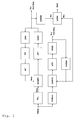
- Figure 1 shows the typical structure of a TV receiver.
- the time constant in the synchronous signal separation SYNCSEP should be switched depending on the source. If the source is a home video recorder, for example, so that the non-standard signal is present, the PLL needs to settle quickly in order to be able to follow the phase jumps of the VCR signal. If it is a standard-compliant signal without phase jumps, a slow time constant is advantageous because it makes the acquisition of the synchronous signals insensitive to noise.
- any comb filter COMB should be switched off as soon as there is a video recorder at the input, since the comb filter function is only ensured if the signal complies with the standards.
- ColourPlus processing which provides a clean separation between luminance and chrominance within a PALplus transmission system. This processing also requires a standard-compliant signal and must be switched off as soon as. B. there is a VCR signal.
- the invention has for its object to provide a method and a circuit arrangement for distinguishing between standard and non-standard composite signals. This object is achieved by the method specified in claim 1.
- the invention is based on the further object of specifying a circuit arrangement for using the method according to the invention. This object is achieved by the circuit arrangement specified in claim 6.
- f SC 1135 4th + 1 625 ⁇ H for PAL systems
- f SC 455 2nd ⁇ H for NTSC systems
- the ink carrier undergoes a phase shift of approximately 180 ° from one line of a first field to a line of the second field 312 lines away. If you add z. B. the ink carrier in line 59 and those in line 371, they are deleted. If the color carrier, which was obtained from the CVBS signal by a color carrier PLL, is scanned with a line-coupled clock, this is only canceled if the input signal has a coupling between the color carrier frequency and the horizontal frequency in accordance with the standards. This behavior can also be used to distinguish between standard and non-standard signals.
- the method according to the invention for distinguishing between standard and non-standard composite signals consists in the fact that one or more differentiation criteria based on a coupling of the Color carrier frequency with the horizontal frequency are used.
- a non-standard signal If a non-standard signal is assumed, it can preferably be examined after adding the color carriers of successive fields whether the sum of the color carriers is less than a certain threshold value.
- a first horizontal signal can preferably be generated using the coupling of the horizontal frequency and the color carrier frequency, and a second horizontal signal can be separated from the composite signal and it can be checked whether the two horizontal signals are stable to one another.
- the circuit arrangement according to the invention for distinguishing between standard and non-standard CVBS signals consists in the fact that one or more differentiation criteria, which are based on a coupling of the color carrier frequency with the horizontal frequency, are used in an evaluation logic.
- a first horizontal signal by means of a control loop using the coupling of the horizontal frequency and the color carrier frequency and a second horizontal signal are advantageous for the detection of a non-standard signal from the television signal a disconnection circuit and a comparison of the two signals is carried out in an evaluation logic.
- For the detection of a standard signal is preferably an analog-digital converter for sampling the color carrier, a memory for storing a sample signal, an adder for adding the stored sample signal and the sample signal of a line of a later field, an absolute value image for forming the absolute value of the Sum signal, an integrator for summing the absolute values and a threshold logic for comparing the summed value with a predetermined threshold value.
- Fig. 2 shows the state diagram for the decision standard signal S or non-standard signal NS. If the current decision is "S", ie if a standard signal is suspected, it is examined whether there is a fixed coupling FSCFH between f SC and f H. If this is not the case, the decision is made that it is a non-standard signal NS. If it has been decided that a non-standard signal is currently present, the color carrier deletion CCC is examined from one field to the next. If the ink carrier is erased, it is a standard signal at the input of the detector.
- the color carrier fscext is recovered from the television signal FBAS using a chrominance PLL CPLL. This is always possible, even with noisy signals with high stability, since a quartz PLL is used for this. Even with video recorders, the ink carrier is stable because it is generated with quartz stability in the recorder.
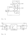
- the aim of the circuit below is to generate a horizontal signal using the coupling of the horizontal frequency and the color carrier frequency.
- the VCO1 Voltage Controlled Oscillator
- a DTO Discrete Time Oscillator
- This generates sample values of the color carrier taking into account the mathematical, theoretical relationship between the line-coupled sampling frequency and the color carrier.
- the circuit shown in Figure 4 is used for this purpose (see BBC Report 2/1986 C. Clarke: "Color encoding and decoding techniques for line-locked sampled PAL and NTSC television signals").
- the upper part provides the phase one respective sample value while the lower one supplies the correct amplitude value for the phase using a ROM.
- a phase comparator COMP1 compares the digitally generated color carrier and the color carrier obtained from the input signal by means of the color carrier PLL.
- the control loop is closed via a loop filter. This control loop ensures that the externally generated color carrier f SCext is in phase with the internal f SCint .
- the clock signal from VCO1 can now be divided by 864 to obtain an H-frequented signal H int .
- a horizontal pulse is obtained from the incoming CVBS signal with a standard separation circuit, which follows the H pulse of the incoming signal.
- a slicer with subsequent PLL (include. VCO2) supplies this H pulse.
- a line-coupled clock f LL2 of 13.5 MHz is also available.
- the internally generated horizontal pulse H int and the external pulse H ext obtained by H separation are stable against one another for a standard signal which mathematically exactly maintains the relationship between the color carrier frequency and the horizontal frequency. These two signals are examined for stability in an evaluation logic. If they move against each other, it is decided that it is a non-standard signal.
- the clock f LL1 can then not be used as a line-coupled sampling clock for an A / D conversion, since this too migrates relative to the line grid.
- f LL1 represents a highly stable clock because it is obtained indirectly from a quartz oscillator, the color carrier quartz oscillator. This clock is therefore suitable for.
- the clock f LL2 now serves as a sampling clock. It is not as stable as f LL1 because it was not derived from the color support. f LL2 is always line-coupled, even with non-standard signals. If you now scan the color carrier f SCext with this clock, it is possible to examine this signal to determine whether the color carrier is erased from one line of the first field to the corresponding line of the second field.
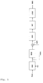
- the corresponding circuit is shown in Figure 5.
- the color carrier is scanned by the analog-digital converter AD with f LL2 and a sample signal thereof is stored in a memory MEM.
- the test signal can be parts of a line. The larger the sample signal, the more sensitive the detection.
- the stored test signal and the test signal of the line of the incoming field are added using an adder ADD.
- the absolute value in ABS is formed from the result of the summation and this is summed up for the duration of the test signal using an integrator INT.
- a threshold value logic LOG2 is then used to check whether the result falls below a predetermined threshold value for the duration of several images. If this is the case, it is assumed that it is a standard signal.
- the non-standard detection described above is then put into operation again and the line-coupled sampling clock is obtained on the basis of the color carrier.
- the invention can e.g. B. for devices for receiving PALplus signals, such as televisions, VCRs or multimedia devices, but also for devices for receiving color television signals according to a further development of other color television systems, such as NTSC.
- PALplus signals such as televisions, VCRs or multimedia devices
- NTSC color television systems
Landscapes
- Engineering & Computer Science (AREA)
- Multimedia (AREA)
- Signal Processing (AREA)
- Processing Of Color Television Signals (AREA)
- Color Television Systems (AREA)
Applications Claiming Priority (2)
| Application Number | Priority Date | Filing Date | Title |
|---|---|---|---|
| DE19618350 | 1996-05-08 | ||
| DE19618350A DE19618350A1 (de) | 1996-05-08 | 1996-05-08 | Verfahren und Schaltungsanordnung zum Unterscheiden zwischen Standard- und Nicht-Standard-FBAS-Signalen |
Publications (2)
| Publication Number | Publication Date |
|---|---|
| EP0806876A2 true EP0806876A2 (fr) | 1997-11-12 |
| EP0806876A3 EP0806876A3 (fr) | 1999-09-01 |
Family
ID=7793618
Family Applications (1)
| Application Number | Title | Priority Date | Filing Date |
|---|---|---|---|
| EP97106865A Withdrawn EP0806876A3 (fr) | 1996-05-08 | 1997-04-25 | Procédé et circuit pour différencier des signaux standard et non-standard |
Country Status (5)
| Country | Link |
|---|---|
| US (1) | US5943101A (fr) |
| EP (1) | EP0806876A3 (fr) |
| JP (1) | JPH1051809A (fr) |
| CN (1) | CN1096191C (fr) |
| DE (1) | DE19618350A1 (fr) |
Cited By (2)
| Publication number | Priority date | Publication date | Assignee | Title |
|---|---|---|---|---|
| EP1111937A1 (fr) * | 1999-12-21 | 2001-06-27 | Sony International (Europe) GmbH | Méthode de génération d'une mesure pour classifier des signaux vidéo |
| EP1047272A3 (fr) * | 1999-04-21 | 2008-07-30 | Matsushita Electric Industrial Co., Ltd. | Appareil pour l'identification des signaux vidéo standard et non-standard |
Families Citing this family (6)
| Publication number | Priority date | Publication date | Assignee | Title |
|---|---|---|---|---|
| US6366327B1 (en) * | 1997-12-22 | 2002-04-02 | Texas Instruments Incorporated | Vertical sync detection and output for video decoder |
| JP2003009160A (ja) * | 2001-06-27 | 2003-01-10 | Pioneer Electronic Corp | カラー方式判別装置およびカラー方式判別方法 |
| FR2856873B1 (fr) * | 2003-06-30 | 2005-09-16 | St Microelectronics Sa | Systeme de reception d'un signal video |
| JP5914836B2 (ja) * | 2011-09-27 | 2016-05-11 | パナソニックIpマネジメント株式会社 | 映像復調装置 |
| US20130197863A1 (en) * | 2012-01-31 | 2013-08-01 | Tata Consultancy Services Limited | Performance and capacity analysis of computing systems |
| CN102740086B (zh) * | 2012-06-26 | 2015-01-28 | 上海屹芯微电子有限公司 | 复合视频广播信号制式的自动识别方法和装置 |
Family Cites Families (12)
| Publication number | Priority date | Publication date | Assignee | Title |
|---|---|---|---|---|
| JPH0787596B2 (ja) * | 1986-06-20 | 1995-09-20 | 株式会社日立製作所 | 信号処理回路 |
| JPH0832059B2 (ja) * | 1987-03-09 | 1996-03-27 | 株式会社日立製作所 | ディジタルテレビジョン信号処理装置 |
| US4860089A (en) * | 1987-04-10 | 1989-08-22 | Ampex Corporation | Apparatus and method for tracking the subcarrier to horizontal sync of a color television signal |
| JP2601840B2 (ja) * | 1987-09-30 | 1997-04-16 | 株式会社東芝 | 映像表示装置 |
| ES2023340A6 (es) * | 1989-07-31 | 1992-01-01 | Gold Star Co | Un circuito de conmutacion automatica de 3 modos de un aparato de television en color. |
| JP2519544B2 (ja) * | 1989-10-19 | 1996-07-31 | シャープ株式会社 | 非標準信号検出装置およびクロック判定装置 |
| FR2658023B1 (fr) * | 1990-02-06 | 1992-05-29 | Sgs Thomson Microelectronics | Procede d'identification automatique d'un standard de television couleur. |
| JPH03250890A (ja) * | 1990-02-28 | 1991-11-08 | Nec Home Electron Ltd | 非標準信号の検出回路 |
| US5111160A (en) * | 1991-04-30 | 1992-05-05 | The Grass Valley Group | Clock generation circuit for multistandard serial digital video with automatic format identification |
| JP3048746B2 (ja) * | 1992-05-18 | 2000-06-05 | 三洋電機株式会社 | Tv信号判別回路 |
| JPH07131819A (ja) * | 1993-10-28 | 1995-05-19 | Toshiba Corp | 映像信号の非標準信号検出回路 |
| DE4423214C2 (de) * | 1994-07-01 | 1998-02-12 | Harris Corp | Multinorm-Dekoder für Videosignale und Verfahren zum Dekodieren von Videosignalen |
-
1996
- 1996-05-08 DE DE19618350A patent/DE19618350A1/de not_active Withdrawn
-
1997
- 1997-04-23 CN CN97110775A patent/CN1096191C/zh not_active Expired - Fee Related
- 1997-04-25 EP EP97106865A patent/EP0806876A3/fr not_active Withdrawn
- 1997-05-01 US US08/847,029 patent/US5943101A/en not_active Expired - Fee Related
- 1997-05-02 JP JP9114719A patent/JPH1051809A/ja not_active Withdrawn
Cited By (2)
| Publication number | Priority date | Publication date | Assignee | Title |
|---|---|---|---|---|
| EP1047272A3 (fr) * | 1999-04-21 | 2008-07-30 | Matsushita Electric Industrial Co., Ltd. | Appareil pour l'identification des signaux vidéo standard et non-standard |
| EP1111937A1 (fr) * | 1999-12-21 | 2001-06-27 | Sony International (Europe) GmbH | Méthode de génération d'une mesure pour classifier des signaux vidéo |
Also Published As
| Publication number | Publication date |
|---|---|
| CN1168066A (zh) | 1997-12-17 |
| DE19618350A1 (de) | 1997-11-13 |
| CN1096191C (zh) | 2002-12-11 |
| EP0806876A3 (fr) | 1999-09-01 |
| JPH1051809A (ja) | 1998-02-20 |
| US5943101A (en) | 1999-08-24 |
Similar Documents
| Publication | Publication Date | Title |
|---|---|---|
| DE69525688T2 (de) | Mehrnormendekodieren für Videosignale und Verfahren zur Dekodierung von Videosignalen | |
| DE3807739C2 (fr) | ||
| EP0567072B1 (fr) | Procédé et dispositif de détection de mode ciné | |
| DE2712025C3 (de) | Anordnung zur Änderung des Formats eines Fernsehbildes | |
| DE68925880T2 (de) | Bewegungsdetektion und Y/C Trennschaltung und -verfahren zur Detektion einer Bewegung in einem Fernsehwiedergabebild | |
| DE3609887C2 (de) | Schaltungsanordnung zur Erzeugung von Bemessungsfaktoren für ein rekursives Filter für Videosignale | |
| DE69419466T2 (de) | Vorrichtung zum anzeigen von zeichen in einem videosystem | |
| DE69608785T2 (de) | Verfahren zur verbesserung der vertikalen auflosung eines fernsehsignals mit verminderten vertikalen chominanzubergangen | |
| DE3751373T2 (de) | Bildwiedergabesystem mit Zeilenfolgeverfahren und Intraframe sowie Interframe-Verarbeitungsweisen. | |
| DE69221419T2 (de) | Digitaler Oscillator und Farbhilfsträger Demodulationsschaltung | |
| DE69712291T2 (de) | Wiedergewinnung der horizontalen synchronisation | |
| EP0806876A2 (fr) | Procédé et circuit pour différencier des signaux standard et non-standard | |
| DE69123270T2 (de) | Verfahren und Gerät für spezielle Videoeffekte | |
| DE3900490A1 (de) | Schaltungsanordnung zur decodierung von farbfernsehsignalen | |
| DE4243960C2 (de) | Frequenzdiskriminator | |
| DD299454A5 (de) | Videoverarbeitungssystem | |
| DE69226570T2 (de) | Kammfilter mit farbträgersynchronisiertem Taktgeber | |
| DE3829965C2 (fr) | ||
| DE3438017A1 (de) | Analog/digital-konverterschaltung, beispielsweise fuer einen digitalen fernsehempfaenger | |
| DE69621313T2 (de) | Fernsehsignalverarbeitungsvorrichtung mit A/D-Wandler | |
| DE68923637T2 (de) | Schaltung zur Verarbeitung eines Videosignals und eine Einfügungsschaltung dafür. | |
| DE69515255T2 (de) | Detektor zur Empfangsdetektion eines nach dem SECAM-Standard kodierten Farbfernsehsignals | |
| DE68904656T2 (de) | Farbfernsehsignaldecoder. | |
| DE69222268T2 (de) | Fernsehempfänger | |
| DE69015676T2 (de) | Einrichtung zur Umwandlung der Bildfrequenz für einen HDTV-Fernsehempfänger und Verfahren zur Bewegungsdetektion in einem kodierten Fernsehbild. |
Legal Events
| Date | Code | Title | Description |
|---|---|---|---|
| PUAI | Public reference made under article 153(3) epc to a published international application that has entered the european phase |
Free format text: ORIGINAL CODE: 0009012 |
|
| AK | Designated contracting states |
Kind code of ref document: A2 Designated state(s): DE FR GB IT |
|
| PUAL | Search report despatched |
Free format text: ORIGINAL CODE: 0009013 |
|
| AK | Designated contracting states |
Kind code of ref document: A3 Designated state(s): DE FR GB IT |
|
| 17P | Request for examination filed |
Effective date: 20000217 |
|
| 17Q | First examination report despatched |
Effective date: 20040511 |
|
| STAA | Information on the status of an ep patent application or granted ep patent |
Free format text: STATUS: THE APPLICATION IS DEEMED TO BE WITHDRAWN |
|
| 18D | Application deemed to be withdrawn |
Effective date: 20041123 |