EP0807048B1 - Soupape de braquage a centre ferme - Google Patents
Soupape de braquage a centre ferme Download PDFInfo
- Publication number
- EP0807048B1 EP0807048B1 EP95941083A EP95941083A EP0807048B1 EP 0807048 B1 EP0807048 B1 EP 0807048B1 EP 95941083 A EP95941083 A EP 95941083A EP 95941083 A EP95941083 A EP 95941083A EP 0807048 B1 EP0807048 B1 EP 0807048B1
- Authority
- EP
- European Patent Office
- Prior art keywords
- input shaft
- steering valve
- hydraulic
- valve
- axial
- Prior art date
- Legal status (The legal status is an assumption and is not a legal conclusion. Google has not performed a legal analysis and makes no representation as to the accuracy of the status listed.)
- Expired - Lifetime
Links
- 238000006243 chemical reaction Methods 0.000 claims description 32
- 239000012530 fluid Substances 0.000 description 9
- 230000007935 neutral effect Effects 0.000 description 5
- 230000004044 response Effects 0.000 description 4
- 230000008901 benefit Effects 0.000 description 3
- 238000007789 sealing Methods 0.000 description 3
- 238000004904 shortening Methods 0.000 description 3
- 238000000034 method Methods 0.000 description 2
- 230000008569 process Effects 0.000 description 2
- 238000010276 construction Methods 0.000 description 1
- 230000008878 coupling Effects 0.000 description 1
- 238000010168 coupling process Methods 0.000 description 1
- 238000005859 coupling reaction Methods 0.000 description 1
- 238000005553 drilling Methods 0.000 description 1
- 210000003746 feather Anatomy 0.000 description 1
- 230000006872 improvement Effects 0.000 description 1
- 238000004519 manufacturing process Methods 0.000 description 1
- 239000002184 metal Substances 0.000 description 1
- 230000009467 reduction Effects 0.000 description 1
- 230000003068 static effect Effects 0.000 description 1
Images

Classifications
-
- B—PERFORMING OPERATIONS; TRANSPORTING
- B62—LAND VEHICLES FOR TRAVELLING OTHERWISE THAN ON RAILS
- B62D—MOTOR VEHICLES; TRAILERS
- B62D5/00—Power-assisted or power-driven steering
- B62D5/06—Power-assisted or power-driven steering fluid, i.e. using a pressurised fluid for most or all the force required for steering a vehicle
- B62D5/08—Power-assisted or power-driven steering fluid, i.e. using a pressurised fluid for most or all the force required for steering a vehicle characterised by type of steering valve used
- B62D5/083—Rotary valves
-
- Y—GENERAL TAGGING OF NEW TECHNOLOGICAL DEVELOPMENTS; GENERAL TAGGING OF CROSS-SECTIONAL TECHNOLOGIES SPANNING OVER SEVERAL SECTIONS OF THE IPC; TECHNICAL SUBJECTS COVERED BY FORMER USPC CROSS-REFERENCE ART COLLECTIONS [XRACs] AND DIGESTS
- Y10—TECHNICAL SUBJECTS COVERED BY FORMER USPC
- Y10T—TECHNICAL SUBJECTS COVERED BY FORMER US CLASSIFICATION
- Y10T137/00—Fluid handling
- Y10T137/8593—Systems
- Y10T137/86493—Multi-way valve unit
- Y10T137/86574—Supply and exhaust
- Y10T137/86638—Rotary valve
- Y10T137/86646—Plug type
- Y10T137/86654—For plural lines
-
- Y—GENERAL TAGGING OF NEW TECHNOLOGICAL DEVELOPMENTS; GENERAL TAGGING OF CROSS-SECTIONAL TECHNOLOGIES SPANNING OVER SEVERAL SECTIONS OF THE IPC; TECHNICAL SUBJECTS COVERED BY FORMER USPC CROSS-REFERENCE ART COLLECTIONS [XRACs] AND DIGESTS
- Y10—TECHNICAL SUBJECTS COVERED BY FORMER USPC
- Y10T—TECHNICAL SUBJECTS COVERED BY FORMER US CLASSIFICATION
- Y10T137/00—Fluid handling
- Y10T137/8593—Systems
- Y10T137/86493—Multi-way valve unit
- Y10T137/86574—Supply and exhaust
- Y10T137/86638—Rotary valve
- Y10T137/86646—Plug type
- Y10T137/86662—Axial and radial flow
Definitions
- the invention relates to a steering valve for supplying an actuator with Hydraulic pressure, consisting of an input shaft, an output shaft, a torsionally elastic element, which has one end with the input shaft and the the other end is connected to the output shaft, a control pressure switching device and a torque / axial force converter unit, wherein at least one hydraulic line in the input shaft for feeding Control pressure is formed and wherein the torque / axial force converter unit is a reaction piston axially guided on the input shaft.
- Steering valves of the generic type are used in particular in power steering systems used.
- the construction of such power steering systems is in itself known.
- An input shaft connected to a handlebar is connected to a an output shaft provided with a pinion.
- both shafts a torsionally elastic element, for example a torsion bar be interposed.
- the pinion acts on the steering rack.
- a control pressure switching device is provided, for example one with the output shaft engaging and surrounding the input shaft Can be valve sleeve. Hydraulic fluid is pumped through a pump System pumped. With a relative rotation of the input shaft to Valve sleeve is supplied hydraulic pressure to a hydraulic motor, which the Rack movement supported in one of the possible directions.
- a valve without a torque / axial force converter unit is from DE 37 31 258 A1 known, with a hydraulic line in the input shaft is trained.
- Steering valves used in power steering systems are roughly divided into two groups distinguished.
- One type of steering valve used in power steering systems is the steering valve with the so-called open center. In the neutral position of the steering valve with an open center, the pump delivers hydraulic fluid with a low Pumped pressure through the open valve into a reservoir. A relative twist the input shaft to the valve sleeve causes the pressure to rise, which is then fed to the servo motor.
- the disadvantage of steering valves with open The middle is that a constant hydraulic flow is maintained even in the neutral position must become. It is therefore a loss of power from the drive motor that is primarily derived from the dynamic pressure and the volume flow.
- Torque / axial force converter unit is a reaction piston with a electrohydraulic converter EHW used.
- Generic steering valves with an open center are still from EP-A-0 302 267 and EP-A-0 667 280.
- EP-A-0 667 280 discloses a steering valve with an open center, which all Features listed in the preamble of the main claim.
- the hydraulic fluid is guided in the input shaft Bore passed into a pressure chamber, which one side through a movable Reaction flask is limited.
- the pressure built up in the pressure chamber attacks the lower surface of the reaction flask delimiting this space at and thus causes the piston to move.
- the piston with a large sealing along its outer surface opposite the valve sleeve Diameter can be sealed.
- the steering valve disclosed in EP-A-0 302 267 has the same for the invention relevant features, such as the steering valve disclosed in EP 0 667 280.
- the hydraulic fluid is in a bore in the input shaft passed into a pressure chamber which is delimited on one side by a reaction flask is.
- the pressure piston becomes shifted while increasing the pressure chamber volume.
- the Pressure piston along its circumferential surface against the valve sleeve with a Large diameter sealing can be sealed.
- Steering valve with a so-called closed center Through the closed The middle position is the hydraulic flow to the two cylinder sides in the neutral position of the steering valve interrupted. So there is no neutral position Hydraulic flow instead.
- An operating pressure is generated by a pump and an accumulator applied to the practically closed valve, which of the then put the pump into operation only within specified limits must be obtained. Because of even when the steering is not operated Steering valves with an open center power loss are considered the power the steering valves with the center closed in the neutral position of the Consider the steering valve.
- these have the disadvantage that practically none direct assignment between an input torque and a working pressure in the Cylinder takes place.
- the modular steering valve has in Housing externally accessible, primarily radial connection holes for Hydraulic lines on. Accordingly, on the housing inner wall Channels, grooves and the like are formed which the hydraulic fluid to the Control grooves, to the effective surfaces of pistons of the torque / axial force converter units and the like. For example, it is common that Guide hydraulic fluid in annular grooves, depending on the rotational position corresponding guide channels are connected to the hydraulic fluid to the required places or to prevent them from flowing. In any case results the need for large diameter seals use to separate the individual hydraulic fluid guide areas to separate. This applies to the tax groove arrangements as well as in particular for the effective surfaces of pistons of the torque / axial force converter units, the through large diameter seals from the surrounding rooms must be sealed off.
- the number of the modular power steering valve connected hydraulic lines also the number of required Seals before. Any additional function, the connection of another Hydraulic line required, thus also makes the use of at least one, usually two seals required that the Seal the guide channel against the neighboring areas.
- a power steering for motor vehicles is known from DE 24 26 201 A1, whereby from For the purpose of minimizing the size, but not with a view to the Seal wear in the torsion element a hydraulic line is trained.
- the present invention has the object of providing a steering valve of the generic type in such a way that the number of seals reduced having a large diameter, and seals can be used with a small diameter that the number of components can be reduced and an improved guidance of the torque / Axial force converter unit is guaranteed.
- a generic steering valve which is a steering valve with a closed center and in which the reaction piston has an internal active surface.
- the torque-to-axial force converter unit points directly to the Input shaft guided reaction piston one facing the input shaft Effective area on.
- the hydraulic line in the Input shaft is formed that that covered by the valve sleeve Input shaft range with that of the torque / axial force converter unit covered input wave range is connected.
- Reaction flask is guided.
- the axial bore in the valve sleeve and Reaction flask area with radial holes on the outside of the Input shaft is guided. It can be provided that the input shaft is a Has axial bore in the region of the longitudinal central axis, in which the Torsion bar is inserted.
- the bore can be designed so that between an annular space between the inner wall of the bore and the outside of the torsion bar remains, which can be used as a hydraulic line. In this case it is only a seal in the lower area is required. There is also the possibility that To design the torsion element itself hollow.
- the torque-axial force converter unit as a reaction piston guided directly on the input shaft is trained.
- the reaction flask particularly advantageously has one of the Active surface facing the input shaft.
- the inventive Power steering valve formed a second axial bore in the output shaft area is.
- This second axial bore advantageously serves the purpose of Hydraulic pressure supply.
- This embodiment of the invention primarily achieves that the Number of large diameter seals can be reduced. This this is because lines from inside are now easier to face lines from the outside can be sealed. The required seals can now be installed in areas that have comparatively small diameters, so that the friction surfaces can be significantly reduced. This will reduce the service life and that Response behavior of a servo valve increased.
- the configuration according to the invention primarily enables use of reaction flask devices with internal active surfaces. Through this Measure omitted a large number of large diameter seals, which are also more stressed because the Reaction piston device is moved axially.
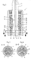
- the power steering valve 1 shown in Figures 1 and 2 comprises a Input shaft 2, which is at its free end with a not shown Steering linkage is connected. Furthermore, the power steering valve 1 includes one Output shaft 3, which is connected to a valve sleeve 4, the Includes input shaft 2.
- the valve sleeve 4 has hydraulic feed bores and control grooves, so that 5 separated from each other by means of seals Areas are formed. The seals 5 have a large diameter and large contact areas in the sealing area, so that it is too corresponding friction comes.
- the output shaft 3 has a pinion 6, which is connected to the rack 7 a chassis arrangement not shown is connected.
- the Shafts are inserted into the housing by means of bearings 8.
- FIG. 1 shows, there is one in the output shaft 3 Axial bore 9 formed as in the lower closure area Blind hole continued and through a radial bore 12 with the Outside is connected.
- the area provided with the radial bore 12 is inserted into a line joint having a ring line 13, which is in turn connected to a hydraulic line 14.
- This figure also shows that an axial bore 10 is formed in the input shaft 2.
- the Input shaft 2 and the output shaft 3 are by a in the Axial bores 9, 10 connected torsion tube 11 connected, which one Series of special functions.
- the tube serves the Execution of the axial bore from the bottom end of the output shaft 3 to into the input shaft 2.
- the torsion tube serves the Providing torsional rigidity against the torsion of the Input shaft 2 with respect to the output shaft 3.
- FIG. 1 shows, the Axial bore 9 into the lower area with a larger diameter executed as in the lowest area of application of the torsion tube 11. This is set the free length of the torsion tube.
- the execution in Figure 1 shows were made easy by the arrangement of the axial bore 10 areas to be sealed with a small diameter.
- a seal 27 between the lowest Locking area and the lowest end of the output shaft 3 is arranged.
- the torsion tube would have continued and opposite the blind hole above the radial bore 12 are sealed can. It is only essential that instead of seals 5 with a very large Diameter seals 27 with a small diameter can be used can, so that the friction is reduced and the service life due to a reduced wear is increased.
- the axial bore 10 ends in the input shaft 2 as a blind hole.
- a second Axial bore 15 formed in the input shaft which is free from the other End until just before the axial bore 10 is guided.
- This axial bore is also designed as a blind hole.
- the axial bore 10 is over the Radial bore 18 and the axial bore 15 via the radial bores 16, 17 connected to the outer surface of the entrance width 2.
- the radial bores are a plurality of star-shaped bores in the mouth area are formed as a control groove.
- a Reaction piston 19 arranged by a spring 20, shown in Embodiment a coil spring is axially biased.
- Balls 21 arranged, which serve the axial guidance of a ring element, the with the spherical cap 23 arranged on the valve sleeve, a ball coupling forms.
- the balls are in the V-shaped Recess in the spherical cap 23 moves because the ball sink 23rd is rotatably connected to the valve sleeve 4. Because of the lower Training, the balls are axially due to the torque Dome pressed out and push the reaction piston 19 against Spring force high. A centering and / or a Force relation can be established. The centering is for every type of Power steering valve cheap.
- the reaction flask can also be used with a Metal bellows interact as a spring element or the like.
- a special advantage also consists in reducing the smaller wetted inner surface of the Control sleeve, so that the static pressure only minor deformations of the Causes sleeve. This allows smaller game fits, which makes the Overall steering efficiency is increased.
- the input shaft 2 opposite the valve sleeve 4 come Control groove-shaped mouths of the radial bores 18 with the control grooves 24 in overlap, so that the hydraulic pressure to the respective side of a Hydraulic motor, not shown, is performed.
- the Control grooves 24 the pressure is passed down to the plane of section A-A, which is shown in Figure 3.
- the hydraulic pressure is, as described, via the control grooves 24 forwarded into the plane of the radial bores 17, which, in the mouth area also designed as a control groove, the hydraulic pressure for the axial bore 15 forward.
- the described embodiment serves to explain the invention and is not directly through the described training of two with each other connected axial bores limited.
Landscapes
- Engineering & Computer Science (AREA)
- Chemical & Material Sciences (AREA)
- Combustion & Propulsion (AREA)
- Transportation (AREA)
- Mechanical Engineering (AREA)
- Power Steering Mechanism (AREA)
Claims (6)
- Soupape de direction pour l'alimentation d'un organe de réglage en pression hydraulique, constituée d'un arbre d'entrée (2), d'un arbre de sortie (3), d'un élément élastique en torsion (11) qui est assemblé par une extrémité à l'arbre d'entrée et par l'autre extrémité à l'arbre de sortie, d'un mécanisme de couplage de pression de commande (4) et d'une unité de conversion moment de couple/force axiale (19 à 23), au moins une conduite hydraulique (15) étant concue dans l'arbre d'entrée pour l'amenée de la pression de commande et l'unité de conversion moment de couple/force axiale (19 à 23) étant un piston de réaction (19) guidé axialement dur l'arbre d'entrée, caractérisée en ce que la soupape de direction est une soupape de direction à centre fermé et en ce que le piston de réaction (19) comporte une surface active (26) à l'intérieur.
- Soupape de direction selon la revendication 1, caractérisée en ce que la conduite hydraulique (15) est conçue de telle sorte qu'elle relie la zone, coopérant avec le mécanisme de couplage de pression de commande (23), de l'arbre d'entrée (2) à la zone, coopérant avec l'unité de conversion moment de couple/force axiale (19 à 23), de l'arbre d'entrée (2).
- Soupape de direction selon l'une quelconque des revendications précédentes, caractérisée en ce que le trou axial (15) avec trous radiaux (16, 17) passe sur le côté extérieur de l'arbre d'entrée.
- Soupape de servodirection selon l'une quelconque des revendications précédentes, caractérisée en ce qu'un trou axial (9) passe axialement à travers l'arbre de sortie (3).
- Soupape de servodirection selon l'une quelconque des revendications précédentes, caractérisée en ce qu'un trou axial (10) passe à travers l'élément de torsion (11).
- Soupape de direction selon l'une quelconque des revendications précédentes, caractérisée en ce que l'arbre d'entrée (2) est placé dans un ajustement avec jeu de l'arbre de sortie (3).
Applications Claiming Priority (2)
| Application Number | Priority Date | Filing Date | Title |
|---|---|---|---|
| PCT/EP1995/004854 WO1997021579A1 (fr) | 1995-12-09 | 1995-12-09 | Soupape de braquage a centre ferme |
| BR9510553A BR9510553A (pt) | 1995-12-09 | 1995-12-09 | Válvula de direçÃo com centro fechado |
Publications (2)
| Publication Number | Publication Date |
|---|---|
| EP0807048A1 EP0807048A1 (fr) | 1997-11-19 |
| EP0807048B1 true EP0807048B1 (fr) | 2001-10-31 |
Family
ID=25664726
Family Applications (1)
| Application Number | Title | Priority Date | Filing Date |
|---|---|---|---|
| EP95941083A Expired - Lifetime EP0807048B1 (fr) | 1995-12-09 | 1995-12-09 | Soupape de braquage a centre ferme |
Country Status (8)
| Country | Link |
|---|---|
| US (1) | US6016837A (fr) |
| EP (1) | EP0807048B1 (fr) |
| JP (1) | JP3125999B2 (fr) |
| BR (1) | BR9510553A (fr) |
| CZ (1) | CZ230397A3 (fr) |
| DE (1) | DE59509786D1 (fr) |
| ES (1) | ES2169164T3 (fr) |
| WO (1) | WO1997021579A1 (fr) |
Citations (2)
| Publication number | Priority date | Publication date | Assignee | Title |
|---|---|---|---|---|
| EP0302267A2 (fr) * | 1987-07-28 | 1989-02-08 | Trw Inc. | Système de direction assistée |
| EP0667280A1 (fr) * | 1994-02-02 | 1995-08-16 | Trw Inc. | Direction assistée |
Family Cites Families (5)
| Publication number | Priority date | Publication date | Assignee | Title |
|---|---|---|---|---|
| GB997065A (en) * | 1963-07-22 | 1965-06-30 | Burman & Sons Ltd | Hydraulically operated vehicle steering mechanisms |
| ES415811A1 (es) * | 1973-06-02 | 1976-02-01 | Bendiberica Sa | Perfeccionamientos en mecanismos de servodireccion para ve-hiculos automoviles. |
| JPH01503773A (ja) * | 1986-09-19 | 1989-12-21 | ツアーンラートファブリーク、フリードリッヒスハーフェン、アクチエンゲゼルシャフト | 液圧式パワーステアリング装置の回転スライド弁 |
| DE4437168C1 (de) * | 1994-10-18 | 1996-02-08 | Trw Fahrwerksyst Gmbh & Co | Lenkventil mit geschlossener Mitte |
| US5697400A (en) * | 1995-06-29 | 1997-12-16 | Trw Fahrwerksysteme Gmbh & Co. Kg | Steering valve |
-
1995
- 1995-12-09 EP EP95941083A patent/EP0807048B1/fr not_active Expired - Lifetime
- 1995-12-09 DE DE59509786T patent/DE59509786D1/de not_active Expired - Lifetime
- 1995-12-09 BR BR9510553A patent/BR9510553A/pt not_active IP Right Cessation
- 1995-12-09 WO PCT/EP1995/004854 patent/WO1997021579A1/fr not_active Ceased
- 1995-12-09 US US08/875,549 patent/US6016837A/en not_active Expired - Fee Related
- 1995-12-09 ES ES95941083T patent/ES2169164T3/es not_active Expired - Lifetime
- 1995-12-09 JP JP52163097A patent/JP3125999B2/ja not_active Expired - Fee Related
- 1995-12-09 CZ CZ972303A patent/CZ230397A3/cs unknown
Patent Citations (2)
| Publication number | Priority date | Publication date | Assignee | Title |
|---|---|---|---|---|
| EP0302267A2 (fr) * | 1987-07-28 | 1989-02-08 | Trw Inc. | Système de direction assistée |
| EP0667280A1 (fr) * | 1994-02-02 | 1995-08-16 | Trw Inc. | Direction assistée |
Also Published As
| Publication number | Publication date |
|---|---|
| WO1997021579A1 (fr) | 1997-06-19 |
| DE59509786D1 (de) | 2001-12-06 |
| US6016837A (en) | 2000-01-25 |
| BR9510553A (pt) | 1998-01-13 |
| ES2169164T3 (es) | 2002-07-01 |
| EP0807048A1 (fr) | 1997-11-19 |
| JPH11500391A (ja) | 1999-01-12 |
| JP3125999B2 (ja) | 2001-01-22 |
| CZ230397A3 (en) | 1997-11-12 |
Similar Documents
| Publication | Publication Date | Title |
|---|---|---|
| DE3882295T2 (de) | Servolenkungssystem. | |
| DE3687876T2 (de) | Ausladungsventil fuer integrierte lenkeinrichtung. | |
| DE3852974T2 (de) | Lenkgetriebe. | |
| DE3737392C2 (fr) | ||
| EP0937206B1 (fr) | Moteur de positionnement pneumatique ou hydraulique muni d'un dispositif de desenclenchement | |
| DE2913484A1 (de) | Hilfskraftlenkung, insbesondere fuer kraftfahrzeuge | |
| DE2160905B2 (de) | Servolenkung mit veränderlichem Obersetzungsverhältnis | |
| EP0737610A2 (fr) | Direction à crémaillère hydraulique | |
| DE2747842C2 (fr) | ||
| DE2426201A1 (de) | Servolenkung fuer kraftfahrzeuge | |
| DE2649509A1 (de) | Hydraulische hilfskraftlenkung fuer kraftfahrzeuge | |
| EP0807049B1 (fr) | Soupape de braquage a centre ferme | |
| DE69401925T2 (de) | Hammermechanismus für felsbohrer | |
| DE4437168C1 (de) | Lenkventil mit geschlossener Mitte | |
| DE3204303C2 (fr) | ||
| DE4437169C1 (de) | Lenkventil mit geschlossener Mitte | |
| DE1755697A1 (de) | Hydraulische Lenkeinrichtung fuer Kraftfahrzeuge | |
| DE3931240A1 (de) | Stossdaempfungseinrichtung mit veraenderlicher daempfungscharakteristik, insbesondere fuer kraftfahrzeuge | |
| DE69106798T2 (de) | Hydraulische hilfskraftverstärkte Lenkeinrichtung. | |
| EP0807048A1 (fr) | Soupape de braquage a centre ferme | |
| DE1060272B (de) | Hilfskraftlenkung fuer Hand- und Hilfskraftbetrieb, insbesondere fuer Kraftfahrzeuge | |
| DE2825790C2 (de) | Stellmotor mit Nachlaufsteuerung | |
| DE2917298C2 (de) | Drehschiebereinrichtung zur Steuerung eines hydrostatischen Servoantriebs | |
| DE3242445C2 (de) | Kraftverstärktes Lenkgetriebe | |
| DE2508268A1 (de) | Steuerkolben mit mindestens zwei steuerkanten, insbesondere fuer ein lenkventil einer hydraulischen servolenkeinrichtung von fahrzeugen |
Legal Events
| Date | Code | Title | Description |
|---|---|---|---|
| PUAI | Public reference made under article 153(3) epc to a published international application that has entered the european phase |
Free format text: ORIGINAL CODE: 0009012 |
|
| 17P | Request for examination filed |
Effective date: 19970709 |
|
| AK | Designated contracting states |
Kind code of ref document: A1 Designated state(s): DE ES FR GB IT SE |
|
| 17Q | First examination report despatched |
Effective date: 19990421 |
|
| GRAG | Despatch of communication of intention to grant |
Free format text: ORIGINAL CODE: EPIDOS AGRA |
|
| GRAG | Despatch of communication of intention to grant |
Free format text: ORIGINAL CODE: EPIDOS AGRA |
|
| GRAH | Despatch of communication of intention to grant a patent |
Free format text: ORIGINAL CODE: EPIDOS IGRA |
|
| GRAH | Despatch of communication of intention to grant a patent |
Free format text: ORIGINAL CODE: EPIDOS IGRA |
|
| GRAA | (expected) grant |
Free format text: ORIGINAL CODE: 0009210 |
|
| AK | Designated contracting states |
Kind code of ref document: B1 Designated state(s): DE ES FR GB IT SE |
|
| REF | Corresponds to: |
Ref document number: 59509786 Country of ref document: DE Date of ref document: 20011206 |
|
| PGFP | Annual fee paid to national office [announced via postgrant information from national office to epo] |
Ref country code: DE Payment date: 20011228 Year of fee payment: 7 |
|
| REG | Reference to a national code |
Ref country code: GB Ref legal event code: IF02 |
|
| PG25 | Lapsed in a contracting state [announced via postgrant information from national office to epo] |
Ref country code: SE Free format text: LAPSE BECAUSE OF FAILURE TO SUBMIT A TRANSLATION OF THE DESCRIPTION OR TO PAY THE FEE WITHIN THE PRESCRIBED TIME-LIMIT Effective date: 20020131 Ref country code: GB Free format text: LAPSE BECAUSE OF NON-PAYMENT OF DUE FEES Effective date: 20020131 |
|
| GBT | Gb: translation of ep patent filed (gb section 77(6)(a)/1977) |
Effective date: 20020118 |
|
| ET | Fr: translation filed | ||
| PG25 | Lapsed in a contracting state [announced via postgrant information from national office to epo] |
Ref country code: DE Free format text: LAPSE BECAUSE OF THE APPLICANT RENOUNCES Effective date: 20020301 |
|
| REG | Reference to a national code |
Ref country code: ES Ref legal event code: FG2A Ref document number: 2169164 Country of ref document: ES Kind code of ref document: T3 |
|
| PG25 | Lapsed in a contracting state [announced via postgrant information from national office to epo] |
Ref country code: FR Free format text: LAPSE BECAUSE OF NON-PAYMENT OF DUE FEES Effective date: 20020830 |
|
| PLBE | No opposition filed within time limit |
Free format text: ORIGINAL CODE: 0009261 |
|
| STAA | Information on the status of an ep patent application or granted ep patent |
Free format text: STATUS: NO OPPOSITION FILED WITHIN TIME LIMIT |
|
| GBPC | Gb: european patent ceased through non-payment of renewal fee |
Effective date: 20020131 |
|
| REG | Reference to a national code |
Ref country code: FR Ref legal event code: ST |
|
| 26N | No opposition filed | ||
| PG25 | Lapsed in a contracting state [announced via postgrant information from national office to epo] |
Ref country code: ES Free format text: LAPSE BECAUSE OF NON-PAYMENT OF DUE FEES Effective date: 20021210 |
|
| REG | Reference to a national code |
Ref country code: ES Ref legal event code: FD2A Effective date: 20030113 |
|
| PG25 | Lapsed in a contracting state [announced via postgrant information from national office to epo] |
Ref country code: IT Free format text: LAPSE BECAUSE OF NON-PAYMENT OF DUE FEES Effective date: 20051209 |