EP0811504B1 - Dispositif de réglage automatique pour régler l'espacement entre la tête d'impression et le cylindre - Google Patents
Dispositif de réglage automatique pour régler l'espacement entre la tête d'impression et le cylindre Download PDFInfo
- Publication number
- EP0811504B1 EP0811504B1 EP97303922A EP97303922A EP0811504B1 EP 0811504 B1 EP0811504 B1 EP 0811504B1 EP 97303922 A EP97303922 A EP 97303922A EP 97303922 A EP97303922 A EP 97303922A EP 0811504 B1 EP0811504 B1 EP 0811504B1
- Authority
- EP
- European Patent Office
- Prior art keywords
- pulse width
- carriage
- recording medium
- platen surface
- pulse
- Prior art date
- Legal status (The legal status is an assumption and is not a legal conclusion. Google has not performed a legal analysis and makes no representation as to the accuracy of the status listed.)
- Expired - Lifetime
Links
Images





Classifications
-
- B—PERFORMING OPERATIONS; TRANSPORTING
- B41—PRINTING; LINING MACHINES; TYPEWRITERS; STAMPS
- B41J—TYPEWRITERS; SELECTIVE PRINTING MECHANISMS, i.e. MECHANISMS PRINTING OTHERWISE THAN FROM A FORME; CORRECTION OF TYPOGRAPHICAL ERRORS
- B41J25/00—Actions or mechanisms not otherwise provided for
- B41J25/304—Bodily-movable mechanisms for print heads or carriages movable towards or from paper surface
- B41J25/308—Bodily-movable mechanisms for print heads or carriages movable towards or from paper surface with print gap adjustment mechanisms
- B41J25/3082—Bodily-movable mechanisms for print heads or carriages movable towards or from paper surface with print gap adjustment mechanisms with print gap adjustment means on the print head carriage, e.g. for rotation around a guide bar or using a rotatable eccentric bearing
-
- B—PERFORMING OPERATIONS; TRANSPORTING
- B41—PRINTING; LINING MACHINES; TYPEWRITERS; STAMPS
- B41J—TYPEWRITERS; SELECTIVE PRINTING MECHANISMS, i.e. MECHANISMS PRINTING OTHERWISE THAN FROM A FORME; CORRECTION OF TYPOGRAPHICAL ERRORS
- B41J25/00—Actions or mechanisms not otherwise provided for
- B41J25/304—Bodily-movable mechanisms for print heads or carriages movable towards or from paper surface
- B41J25/308—Bodily-movable mechanisms for print heads or carriages movable towards or from paper surface with print gap adjustment mechanisms
Definitions
- the present invention relates to a technique for automatically adjusting a gap between the platen and the printing head in a printer in accordance with the thickness of a recording medium. More particularly, the present invention relates to a technique for judging the thickness of a recording medium charged on the platen and adjusting a gap between the platen and the printing head to an appropriate distance.
- Japanese Examined Patent Publication No. 4-14634 discloses a printer in which the relative positions of the platen and the carriage are automatically changed; that is the platen gap is automatically adjusted, which will be described below.
- the printer in the above-noted publication comprises: a step motor for moving a carriage in a direction perpendicular to a platen; an encoder for generating a pulse signal in accordance with the movement of the carriage; and a control section for processing a feedback pulse signal sent from the encoder.
- the recording head is moved onto the platen side, it comes into contact with a recording medium, so that the step motor enters an out-of-step condition.
- the out-of-step condition of the step motor is detected by a change in the encoder signal.
- the thickness of the recording medium is determined. According to the determined thickness, the relative positions of the platen and the carriage are automatically adjusted, that is, the platen gap is automatically adjusted.
- the recording head is pressed against the recording medium by an unnecessarily strong force. Accordingly, the recording head is damaged and the recording medium is soiled.
- EP-A-657294 discloses a platen gap adjusting device comprising:
- the thickness of the recording medium can be accurately measured only when the carriage comes into pressure contact with the recording medium by a necessary minimum force. Therefore, it is possible to prevent the recording head from being damaged and to prevent the recording medium from being soiled.
- the recording head since the recording head contacts the recording medium placed on the platen surface with necessary minimum pressure, when a load given to the carriage is changed by the influence of paper powder accumulating in the guide member over a long period of time, the judgement of contact of the recording head with the recording medium cannot be conducted accurately.
- the present invention has been designed to solve the above problems.
- this invention provides an automatic platen gap adjusting device for adjusting a gap between a platen and a recording head of a printer, comprising:
- this invention provides a method for automatically adjusting a platen gap between a platen and a recording head of a printer, comprising:
- Fig. 1 illustrates a mechanism for adjusting a relative gap between the platen and the recording head of the serial printer to which the present invention is applied.
- Fig. 2 illustrates the structure of the printer with respect to the axial direction of the platen.
- reference numeral 1 is a carriage into which the impact wire type recording head 2 is incorporated.
- the carriage 1 is mounted on a guide shaft 3 and a stationary guide shaft 4, wherein the guide shaft 3 is rotatably attached to the base in an eccentric condition.
- the carriage 1 can be moved in the direction of arrow A in the drawing.
- Relative gap G between the recording head 2 and the platen 5 can be arbitrarily adjusted in accordance with the rotation of the guide shaft 3.
- the carriage 1 is connected to a carriage motor 6, which is a direct current motor in this example, via a timing belt 9. Therefore, the carriage 1 can be reciprocated in the axial direction of the platen shaft shown by arrow B in the drawing while the gap G, adjusted by the guide shaft 3, is maintained at a predetermined value.
- Reference numeral 10 is a step motor for rotating the guide shaft 3.
- a step motor of 48 poles excited by means of 2 - 2 phase For example, the step motor 10 is driven by the drive pulse signals output at a period of 3.5 ms when running at a constant speed.
- This step motor 10 is connected with a gear 12 mounted on the guide shaft 3, via a reduction gear 11.
- a code disk 15 of a first encoder 14 is attached to a shaft 13 of the step motor 10.
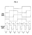
- the code disk 15 of the first encoder 14 is used for outputting pulse signals of a constant width, the number of which is proportional to the rotational angle. As illustrated in Fig. 4, the code pattern of the code disk 15 is determined so that a signal of one pulse width can be output from a code detector 16 in synchronisation with the drive of one phase of the step motor 10.
- Reference numeral 18 is an end position detector.
- the end position detector is positioned so that a signal can be output from the detector when the carriage 1 is withdrawn to the home position, that is, when the carriage 1 is withdrawn to a reference position.
- a micro-switch is used as the end position detector.
- a code disk 22 is fixed to a member for driving the carriage in the primary scanning direction.
- an idle roller 20 for the timing belt 9 is used as the member to which the code disk 22 is fixed.
- a second encoder 25 that includes a code detector 24 for detecting the code disk 22.
- Reference numeral 26 is a control unit that receives signals sent from the encoder 14 and the end position detector 18 and controls the step motor 10 in accordance with a flow chart described later.
- Fig. 3 illustrates an example of the control unit 26 described above.
- Reference numeral 30 is a motor driver for driving the step motor 10 so that the carriage 1 can be moved in the direction perpendicular to the surface of the platen 5.
- Reference numeral 31 is a pulse width detector. This pulse width detector 31 is operated as follows. Pulse width T 1 , T 2 , T 3 , •••, T i (shown in Fig. 4) of a pulse signal, which is output from the encoder 14 each time the step motor 10 conducts driving with respect to one phase, is detected. An average of a predetermined number of signals, for example, an average of four signals, is found.
- Time T0 of a predetermined number of pulse signals sent from the encoder 14 in the case of normal driving, that is, in the case of driving without being affected by a load, is also determined. Then, a difference between the above average of a predetermined number of signals and the time T0 is output.
- Reference numeral 32 is a writing device.
- the writing device 32 is operated as follows.
- the relative co-ordinate with respect to the reference position of the carriage 1 is detected from the number of pulse signals sent from the encoder 14, and the signal tn of the pulse width detector 31 at a predetermined position is stored in a memory 33.
- Reference numeral 34 is a difference detector.
- the difference detector 34 is operated as follows.
- the relative co-ordinate with respect to the reference position of the carriage 1 is detected from the signal sent from the encoder 14.
- a difference, between the pulse width tn stored in the memory 33 and the signal t n output from the pulse width detector 31 in accordance with the pulse signal sent from the encoder 14, is calculated.
- Reference numeral 35 is a contact detector.
- the contact detector 35 is operated as follows. A point of time at which the time width of the signal t n sent from the difference detector 34 exceeds a predetermined time TP is judged to be a contact point, and a signal is output to the sheet thickness calculator 36 described later.
- Reference numeral 36 is a sheet thickness calculator.
- the sheet thickness calculator 36 starts counting pulse signals sent from the encoder 14 in accordance with a signal sent from the end position detecting device 18.
- the sheet thickness calculator 36 stops counting pulse signals in accordance with a signal sent from the contact detector 35. According to the number of the counted pulse signals, the thickness of a recording medium is calculated.
- Reference numeral 37 is a motor control.
- the motor control 37 controls the step motor 10 for adjusting a platen gap.
- a loading switch (not shown) of the recording medium is pressed down
- the carriage 1 is moved in a direction so that the carriage 1 can be separated from the platen 5, that is, the carriage is withdrawn until a signal is output from the position detector 18, so that the carriage is set at the reference position.
- the carriage 1 is moved in the direction of the platen, and the step motor 10 is driven so that the carriage 1 can be withdrawn to a position at which the most appropriate gap can be formed with respect to the recording medium detecting the thickness of the recording medium.
- step 101 An electric power switch (not shown) of the printer is turned on in step 100.
- step 101 the motor control 37 rotates the step motor 10 clockwise (CW) by a predetermined number of revolutions, for example, by a number of revolutions corresponding to four pulses, so that the carriage 1 is made to advance by a minute distance in the direction of the carriage.
- steps 102 the step motor 10 is rotated counterclockwise (CCW) by a predetermined number of revolutions, for example, by the number of revolutions corresponding to four pulses, so that the carriage 1 is withdrawn to the initial position. In this way, back lash of the reduction gear 11 is removed.
- step motor 10 is rotated clockwise by the number of revolutions corresponding to 50 pulses in steps 108.
- the step motor 10 is rotated counterclockwise (CCW) in step 109 by the number of revolutions corresponding to 50 pulses, so that the carriage 1 is moved, and it is confirmed whether or not a signal has been sent from the end position detecting device 18 in step 110.
- CCW counterclockwise
- the step motor 10 is rotated counterclockwise (CCW) by every pulse in step 113 in Fig. 6.
- CCW counterclockwise
- the step motor 10 is rotated clockwise (CW) by the number of revolutions corresponding to one pulse in step 115, and a reference value, for example, 550 is accommodated in the sheet thickness calculator 36, so that a co-ordinate value to be used as a reference position, is accommodated in step 116.
- drive pulse signals are output to the step motor 10, so that the carriage 1 is made to advance toward the platen 5.
- the reference value (550) accommodated in the sheet thickness calculator 36 is decreased in accordance with the pulse signal sent from the encoder 14 in step 117 in Fig. 7. Further, each time one pulse signal is output from the encoder 14, its pulse width T i is detected in step 118.
- the pulse width detector 31 calculates the average (T i-3 + T i-2 + T i-1 + T i )/4 of the above values, and the reference value T0 is subtracted and the result is output as a delay time t n in step 120.
- the writing device 32 stores the delay time t n in the memory 33 in accordance with the present relative position with respect to the reference position of the carriage 1 detected by the encoder 14 in step 120.
- step 121 Due to the foregoing, as shown by reference character A in Fig. 9, a change in the pulse width of the pulse signal sent from the encoder 14 at each position from the reference position to the platen 5, that is, the delay time t 1 , t 2 , •••, t n is stored in the memory 33.
- step 124 After a sheet of paper has been fed by the operation of a loading switch (not shown) and others in step 124, the carriage 1 is subjected to movement control and moved into a printing region, and the aforementioned reference position determination processing is conducted.
- a drive pulse signal is output to the step motor 10, so that the carriage 1 is moved toward the platen 5.
- the sheet thickness calculator 36 decreases the number 550, which has been previously accommodated, in accordance with the pulse signal sent from the encoder 14 in step 125.
- signals, the number of which is a predetermined value N for example, four signals are continuously output from the encoder 14 in step 127, the average (T i-3 + T i-2 + T i-1 + T i )/4 of the above values is calculated, and the reference value T0 of the pulse width is subtracted from the above average.
- the difference detector 34 subtracts the delay time tn at this position stored in the memory 33. Therefore, in step 128 the difference detector 34 calculates the delay time tn' from which an amount of time corresponding to fluctuation of the load caused by the friction in the movement passage from the carriage 1 to the platen is removed.
- a pulse signal of the encoder 14 in the contact detecting process is subjected to subtraction processing. Due to the foregoing, an amount of time corresponding to the delay of time (hatched portion in the drawing) caused by the friction in the process of moving can be removed from the signal t n of the pulse width detector means 31 shown by reference character A in Fig. 9. Accordingly, as shown by reference character B, it is possible to obtain the delay time t n from which an error caused by the fluctuation of the load in the moving passage of the carriage 1 is removed.
- the difference ⁇ t' detected by the difference detector 34 exceeds reference value Tp used for judging the contact of the recording head 2 with the platen 5 in step 131. Accordingly, a signal is output from the contact detector 35.
- the sheet thickness calculator 36 calculates the sheet thickness by a difference between the counted value at this time and the reference value (550) stored as a reference position. Due to the foregoing, as shown in Fig. 9, when a pulse signal sent from the encoder 14 is extended longer than the reference time by a predetermined value, in this example, when a pulse signal sent from the encoder 14 is extended longer than the reference time by 470 nano-seconds, it is judged that the recording head has come to the contact position. Accordingly, even if paper powder adheres to the carriage 1 and the fluctuation of the load is temporarily caused, it is possible to judge the contact position such that detection error ⁇ G is eliminated from the judgement.
- the step motor 10 has not been put into an out-of-step condition. Therefore, the recording medium is not subjected to high pressure. For this reason, there is no possibility that the recording medium is soiled or the recording head is damaged.
- the motor control 37 drives the step motor 10, so that the carriage 1 is withdrawn from the platen 5 to a predetermined position. Then, the carriage 1 is moved to the platen side in accordance with the calculated thickness of the recording medium so that the most appropriate platen gap can be obtained, and the carriage 1 is prevented from moving toward the platen in step 133.
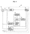
- Fig. 11 illustrates the above example.
- reference numeral 40 is a function inducing device. This function inducing device 40 is operated as follows. Delay time at a plurality of points t p1 , t p2 , t p3 ••• t pn , the relative positions with respect to the reference position of which are clear, is received from the pulse width detector 31, and the function F(Pn) to express time delay of the carriage 1 in the direction of the platen is induced. The thus induced function is written in the memory 41.
- Reference numeral 42 is a difference calculator. A difference between the delay time t n sent from the pulse width detector 31 and correction time t n at the present position found by the function F(Pn) stored in the memory 41 is calculated and output to the contact detector 35.
- an amount of pulse width corresponding to the friction in the moving passage can be accurately offset in accordance with the function F(Pn) stored in the memory 41, the amount of data of which is small. Therefore, compared with the above example in which data at each point is successively stored, it is possible to decrease an amount of data to be stored in the memory 41. Accordingly, it is possible to use memory having a small capacity.
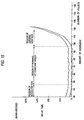
- a gradient of the function F(Pn) to express an amount of load is greatly changed in accordance with a state in which the recording head is running without being given any load, a state in which the recording head comes into contact with the recording medium and starts moving while it resists an elasticity of the recording medium, and a state in which the recording medium is compressed to a limit by the recording head so that the mechanism such as the platen is elastically deformed. That is, until the recording head moves from the reference position and comes into contact with the platen, the load given to the recording head is given by a frictional force between the recording head and the guide member. Therefore, the gradient is substantially flat. At the beginning of contact of the recording head with the recording medium, a load given to the recording head is determined by the elasticity of the recording medium.
- the gradient is substantially linearly increased in accordance with a modulus of elasticity of the recording medium.
- the same method may be adopted.
- Delay time t p1 , t p2 , t p3 , •••, t pn at a plurality of points P1, P2, P3, ••• ⁇ , Pn with respect to the reference position is corrected by the function F(Pn), and the function F'(Pn) is found by the same method.
- the function F(Pn) is differentiated, it is possible to obtain two relatively large points of inflection H1 and H2 as illustrated in Fig. 10. Consequently, it is possible to judge a state of the recording head according to the points of inflection.
- the recording head it is possible to determine whether a) the recording head is running without any load, b) the recording head comes into contact with the recording medium and compresses only the recording medium, or c) the recording head has compressed the recording medium to a limit and starts conducting elastic deformation of the mechanism. Even if the point of inflection H2 at which the recording medium is compressed to a limit is determined to be a contact point, a high pressure resulting in an out-of-step condition of the step motor is not applied to the recording medium. Accordingly, it is possible to detect the contact point without soiling the recording medium or damaging the recording head.
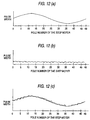
- the step motor 10 has a stator and a rotor, the numbers of poles of which are usually the same.
- the stator is provided with 48 salient poles and the rotor is provided with 48 poles, and when a predetermined number of drive pulses are fed to the stator, the rotor is rotated by an amount of rotations corresponding to the number of poles which coincides with the number of drive pulses, without conducting feedback control, and the rotation is stopped at a stabilising point of each pole.
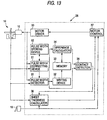
- Fig. 13 illustrates an example to solve the above problems.
- Reference numeral 51 is a pulse width correcting device.
- the step motor 10 starts rotating and passes through an accelerating region and each pole of the rotor is moved to each pole of the stator. In this case, under the condition in which overshooting is not caused; that is, under the condition of running at a constant speed, the width of the pulse signal successively output from the encoder 14 is detected.
- the thus detected pulse width is made to correspond to the position of the code on the code disk of the encoder 14, or alternatively, the thus detected pulse width is made to correspond to each pole of the step motor 10, and the pulse width is stored in the pulse width storing device 52 as the pulse width data D1, D2, D3, •••, D47 and D48.
- the step motor 10 When the step motor 10 is rotated by an amount of revolutions corresponding to 48 poles, for example, each time a pulse signal, which is a detection signal, is output from the encoder 14, the corresponding pulse width data D1, D2, D3, •••, D47, D48 is read out from the pulse width storing means 51.
- reference numeral 52 is the pulse width storing device having addresses, the number of which is the same as the number of poles of the stepping motor 10 or the number of the codes on the code disk of the encoder 14.
- the pulse width storing device 52 is preferably composed in such a manner that the memory, corresponding to the number of the storing areas of which is the same as the number of poles of the step motor 10, can be read and written in circulation as illustrated in Fig. 14.
- data is stored in the pulse width storing device 52 as follows. After the completion of determination of the reference position, a drive pulse signal is output to the step motor 10, so that the carriage 1 is made to proceed toward the platen 5. After the step motor 10 has been accelerated, the step motor is rotated at a constant speed. At this time, for example, when an amount of revolutions corresponding to 30 pulses has been completed, each time one drive pulse is output from the motor drive means 30, the pulse width correcting device 51 detects a signal sent from the encoder 14. and this data is stored in the pulse width storing device 52.
- the pulse width detector 31 detects the width of each pulse signal output from the encoder 14 while the width of each pulse signal is being corrected by the pulse width correcting device 51 in accordance with the pulse width D1, D2, D3, •••, D47, D48 stored in the pulse width storing device 52, or in accordance with the difference D1 - D0, D2 - D0, D3 - DO, •••, D47 - D0, D48 - D0, wherein DO is a constant value.
- the correction is conducted as described above, after the completion of the n-th revolution, as shown by curve D in Fig. 14, it is possible to obtain a pulse width signal from which a surge caused by the fluctuating elements in the pulse motor 10 and encoder 14 is removed.
- the pulse width detector 31 detects the width of each pulse signal output from the encoder 14 while the width of each pulse signal is being corrected by the pulse width correcting device 51 in accordance with the pulse width D1, D2, D3, •••, D47, D48 stored in the pulse width storing device 52, or in accordance with the difference D1 - D0, D2 - D0, D3 - D0, •••, D47 - D0, D48 - D0, wherein D0 is a constant value.
- an automatic adjusting device for adjusting a platen gap of the present invention comprises: a step motor for moving a carriage, on which a recording head is mounted, in a direction perpendicular to a platen surface; a moving distance detector, which may detect drive signals output from said step motor, for outputting pulse signals of a constant pulse width, the number of which coincides with a moving distance of the carriage; a pulse width detector for detecting a pulse width of the pulse signal when the carriage is moved from a reference position in a direction of the platen; a storing device for storing reference data of the pulse width of the pulse signal corresponding to a position of the platen when the carriage is moved under the condition that the platen is not charged with a recording medium; a difference calculator for calculating a difference between a pulse width of the pulse signal sent from the pulse width detector when the carriage is moved under the condition that the platen is charged with a recording medium, and a pulse width of the pulse signal stored in the storing device, when the platen is located at a
Landscapes
- Common Mechanisms (AREA)
- Character Spaces And Line Spaces In Printers (AREA)
Claims (20)
- Dispositif de réglage automatique d'espace de plateau permettant de régler un espace entre un plateau (5) et une tête d'enregistrement (2) d'une imprimante, comprenant :caractérisé en ce qu'il comprend en outre :un moteur pas à pas (10) pour déplacer un chariot (1) sur lequel ladite tête d'enregistrement est montée, suivant une direction perpendiculaire à une surface de plateau ;un moyen de détection de distance de déplacement (14) pour détecter un déplacement dudit moteur pas à pas et pour émettre en sortie des signaux impulsionnels dont le nombre correspond à une distance de déplacement dudit chariot ;un moyen de détection de largeur d'impulsion (31) pour détecter une largeur d'impulsion d'un signal impulsionnel lorsque ledit chariot est déplacé depuis une position de référence suivant une direction vers ladite surface de plateau ; etun moyen de commande (30, 36, 37) pour déterminer une épaisseur dudit support d'enregistrement qui est positionné sur ledit plateau et pour commander ledit espace de manière à ce qu'il corresponde à ladite épaisseur dudit support d'enregistrement, etun moyen de détermination de position (33, 51) pour stocker une position de référence dudit chariot et pour déterminer des données de position de référence correspondant au déplacement dudit chariot en direction de ladite surface de plateau lorsqu'un support d'enregistrement n'est pas positionné sur ladite surface de plateau en fonction de largeurs d'impulsion comme reçu depuis ledit moyen de détection de largeur d'impulsion ;un moyen de calcul de différence (34) pour calculer une différence entre des données de position qui sont émises en sortie depuis ledit moyen de détection de largeur d'impulsion en correspondance avec un déplacement dudit chariot en direction de ladite surface de plateau lorsqu'un support d'enregistrement est positionné sur ladite surface de plateau et lesdites données de position de référence et pour émettre en sortie un signal de différence ; etun moyen de détermination de contact (35) pour déterminer une position de contact de ladite tête d'enregistrement avec ladite surface de plateau conformément audit signal de différence.
- Dispositif de réglage automatique d'espace selon la revendication 1, dans lequel :lesdites données de position de référence sont des données de largeur d'impulsion de référence qui correspondent à un déplacement dudit chariot en direction de ladite surface de plateau lorsqu'un support d'enregistrement n'est pas positionné sur ladite surface de plateau ;ledit moyen de détermination de position comprend une mémoire (33) pour stocker ladite position de référence dudit chariot et lesdites données de largeur d'impulsion de référence ; etledit moyen de calcul de différence (34) est adapté pour calculer une différence entre des données de largeur d'impulsion qui sont émises en sortie depuis ledit moyen de détection de largeur d'impulsion en correspondance avec un déplacement dudit chariot en direction de ladite surface de plateau lorsqu'un support d'enregistrement est positionné sur ladite surface de plateau et lesdites données de largeur d'impulsion de référence.
- Dispositif de réglage automatique d'espace selon la revendication 1 ou 2, dans lequel ledit moyen de détection de largeur d'impulsion est agencé pour calculer une valeur moyenne de largeurs d'impulsion desdits signaux impulsionnels et pour émettre en sortie un signal de valeur moyenne.
- Dispositif de réglage automatique d'espace selon la revendication 1, dans lequel :lesdites données de position de référence sont des données de retard temporel corrigées ; et dans lequelledit moyen de détermination de position comprend une mémoire (33) pour stocker une fonction de détermination de position et ladite position de référence dudit chariot ; etun moyen (51) pour recevoir des largeurs d'impulsion desdits signaux impulsionnels au niveau d'une pluralité de points comme émis en sortie depuis le moyen de détection de distance de déplacement et pour déterminer lesdites données de retard temporel corrigées au niveau desdits points, de façon respective, sur la base d'une position relative dudit chariot par rapport à ladite position de référence conformément à ladite fonction de détermination de position qui est stockée dans ladite mémoire ; et dans lequelledit moyen de calcul de différence (34) est adapté pour calculer une différence entre des données de retard temporel qui sont émises en sortie depuis ledit moyen de détection de largeur d'impulsion et lesdites données de retard temporel corrigées.
- Dispositif de réglage automatique d'espace selon la revendication 1, dans lequel :lesdites données de position de référence sont des données de largeur d'impulsion de référence correspondant à un déplacement dudit chariot en direction de ladite surface de plateau lorsqu'un support d'enregistrement n'est pas positionné sur ladite surface de plateau ;ledit moyen de détermination de position comprend un moyen de correction de largeur d'impulsion (51, 52) pour stocker des largeurs d'impulsion de signaux impulsionnels en correspondance avec un tour dudit moteur pas à pas comme successivement émis en sortie depuis ledit moyen de détection de distance de déplacement lorsque ledit moteur pas à pas entraíne ledit chariot à une vitesse constante, dans lequel des largeurs d'impulsion stockées représentent des données de correction, pour corriger successivement lesdits signaux impulsionnels qui sont émis en sortie depuis ledit moyen de détection de distance de déplacement conformément auxdites données de correction et pour émettre en sortie lesdits signaux impulsionnels corrigés successivement sur ledit moyen de détection de largeur d'impulsion ;ledit moyen de détection de largeur d'impulsion (31) est adapté pour recevoir les signaux impulsionnels corrigés successivement et pour émettre en sortie des données de largeur d'impulsion ; et dans lequelle dispositif de réglage automatique d'espace comprend en outre une mémoire (33) pour stocker ladite position de référence dudit chariot et lesdites données de largeur d'impulsion de référence ; etledit moyen de calcul de différence (34) est adapté pour calculer une différence entre des données de largeur d'impulsion qui sont émises en sortie depuis ledit moyen de détection de largeur d'impulsion en correspondance avec un déplacement dudit chariot en direction de ladite surface de plateau lorsqu'un support d'enregistrement est positionné sur ladite surface de plateau et lesdites données de largeur d'impulsion de référence.
- Dispositif de réglage automatique d'espace selon l'une quelconque des revendications précédentes, dans lequel ledit moyen de détermination de contact (35) est adapté pour déterminer ladite position de contact lorsque ledit signal de différence est au moins égal à une valeur prédéterminée.
- Dispositif de réglage automatique d'espace selon l'une quelconque des revendications 1 à 5, dans lequel ledit moyen de détermination de contact (35) est adapté pour calculer une valeur intégrée dudit signal de différence et pour comparer ladite valeur intégrée à une valeur prédéterminée, dans lequel ladite position de contact est détectée lorsque ledit signal intégré est au moins égal à ladite valeur prédéterminée.
- Dispositif de réglage automatique d'espace selon l'une quelconque des revendications 1 à 5, dans lequel ledit moyen de détermination de contact (35) est adapté pour déterminer ladite position de contact sur la base d'un point d'inflexion (H1, H2) d'un taux de variation dudit signal de différence.
- Dispositif de réglage automatique d'espace selon l'une quelconque des revendications précédentes, dans lequel ledit moyen de commande détermine l'épaisseur dudit support d'enregistrement sur la base d'une différence entre ladite position de contact et ladite position de référence.
- Dispositif de réglage automatique d'espace selon l'une quelconque des revendications précédentes, comprenant en outre :un moyen de détection de position de référence (18) pour détecter lorsque ledit chariot est à ladite position de référence ; etun moyen de calcul d'épaisseur de feuille (36) pour calculer ladite épaisseur dudit support d'enregistrement en comptant lesdits signaux impulsionnels en provenance dudit moyen de détection de distance de déplacement et en diminuant une valeur de position de référence prédéterminée lorsque chaque signal impulsionnel est détecté.
- Dispositif de réglage automatique d'espace selon la revendication 10, dans lequel ledit moyen de commande déplace ledit chariot d'une distance prédéterminée avant de commencer un traitement de détermination de contact et dans lequel ladite position de référence est déterminée comme étant une position au niveau de laquelle un signal est émis en sortie à partir dudit moyen de détection de position de référence.
- Procédé permettant de régler automatiquement un espace de plateau entre un plateau (5) et une tête d'enregistrement (2) d'une imprimante, comprenant :le déplacement d'un chariot (1), sur lequel ladite tête d'enregistrement est montée, suivant une direction perpendiculaire à une surface de plateau ;la détection d'un déplacement d'un moteur pas à pas (10) ;l'émission en sortie de signaux impulsionnels dont le nombre correspond à une distance de déplacement dudit chariot ;la détection d'une largeur d'impulsion d'un signal impulsionnel lorsque ledit chariot est déplacé depuis une position de référence suivant une direction vers ladite surface de plateau au moyen d'un moyen de détection de largeur d'impulsion ;la détermination d'une épaisseur dudit support d'enregistrement qui est positionné suc ledit plateau ; etla commande dudit espace de manière à ce qu'il corresponde à ladite épaisseur dudit support d'enregistrement, et caractérisé en ce qu'il comprend en outre, avant la détermination de l'épaisseur dudit support d'enregistrement :le stockage d'une position de référence dudit chariot ;la détermination de données de position de référence correspondant au déplacement dudit chariot en direction de ladite surface de plateau lorsqu'un support d'enregistrement n'est pas positionné sur ladite surface de plateau en fonction de largeurs d'impulsion qui sont reçues depuis ledit moyen de détection de largeur d'impulsion ;le calcul d'une différence entre des données de position qui sont émises en sortie depuis un moyen de détection de largeur d'impulsion en correspondance avec un déplacement dudit chariot en direction de ladite surface de plateau lorsqu'un support d'enregistrement est positionné sur ladite surface de plateau et lesdites données de position de référence afin de déterminer un signal de différence ; etla détermination d'une position de contact de ladite tête d'enregistrement avec ladite surface de plateau conformément audit signal de différence.
- Procédé selon la revendication 12, dans lequel :lesdites données de position de référence sont des données de largeur d'impulsion de référence qui correspondent à un déplacement dudit chariot en direction de ladite surface de plateau lorsqu'un support d'enregistrement n'est pas positionné sur ladite surface de plateau ; etladite différence est une différence entre des données de largeur d'impulsion qui sont émises en sortie depuis ledit moyen de détection de largeur d'impulsion en correspondance avec un déplacement dudit chariot en direction de ladite surface de plateau lorsqu'un support d'enregistrement est positionné sur ladite surface de plateau et lesdites données de largeur d'impulsion de référence.
- Procédé selon la revendication 12, dans lequel une détermination des données de position de référence comprend :le stockage d'une fonction de détermination de position ;la réception de largeurs d'impulsion desdits signaux impulsionnels au niveau d'une pluralité de points comme émis en sortie depuis un moyen de détection de distance de déplacement ;la détermination de données de retard temporel corrigées au niveau desdits points, respectivement sur la base d'une position relative dudit chariot par rapport à ladite position de référence conformément à ladite fonction de détermination de position stockée ; et dans lequelle calcul d'une différence comprend le calcul d'une différence entre les données de retard temporel qui sont émises en sortie depuis un moyen de détection de largeur d'impulsion et lesdites données de retard temporel corrigées afin de déterminer ledit signal de différence.
- Procédé selon la revendication 14, dans lequel ladite fonction de détermination de position est stockée dans une mémoire.
- Procédé selon la revendication 12, dans lequel la détermination de données de position de référence comprend :le stockage de largeurs d'impulsion des signaux impulsionnels correspondant à un tour dudit moteur pas à pas comme successivement émis en sortie à partir d'un moyen de détection de distance de déplacement lorsque ledit moteur pas à pas entraíne ledit chariot à une vitesse constante, où les largeurs d'impulsion stockées représentent des données de correction ;la correction successive desdits signaux impulsionnels qui sont émis en sortie depuis ledit moyen de détection de distance de déplacement conformément auxdites données de correction ;l'émission en sortie desdits signaux impulsionnels corrigés successivement sur ledit moyen de détection de largeur d'impulsion ;le stockage desdites données de position de référence en tant que données de largeur d'impulsion de référence correspondant à un déplacement dudit chariot en direction de ladite surface de plateau lorsqu'un support d'enregistrement n'est pas positionné sur ladite surface de plateau ; et dans lequelle calcul d'une différence comprend un calcul d'une différence entre des données de largeur d'impulsion qui sont émises en sortie depuis ledit moyen de détection de largeur d'impulsion en correspondance avec un déplacement dudit chariot en direction de ladite surface de plateau lorsqu'un support d'enregistrement est positionné sur ladite surface de plateau et lesdites données de largeur d'impulsion de référence afin de déterminer un signal de différence.
- Procédé selon l'une quelconque des revendications 12 à 16, dans lequel la détermination d'une position de contact comprend la détermination d'une position de contact lorsque ledit signal de différence est au moins égal à une valeur prédéterminée.
- Procédé selon l'une quelconque des revendications 12 à 16, dans lequel la détermination d'une position de contact comprend :dans lequel ladite position de contact est détectée lorsque ledit signal intégré est au moins égal à ladite valeur prédéterminée.le calcul d'une valeur intégrée dudit signal de différence afin de générer un signal intégré ; etla comparaison dudit signal intégré avec une valeur prédéterminée,
- Procédé selon l'une quelconque des revendications 12 à 16, dans lequel la détermination d'une position de contact comprend la détermination d'une position de contact sur la base d'un point d'inflexion d'un taux de variation dudit signal de différence.
- Procédé selon l'une quelconque des revendications 12 à 19, dans lequel ladite épaisseur dudit support d'enregistrement est basée sur une différence entre ladite position de contact et ladite position de référence.
Applications Claiming Priority (6)
| Application Number | Priority Date | Filing Date | Title |
|---|---|---|---|
| JP166836/96 | 1996-06-06 | ||
| JP16683696 | 1996-06-06 | ||
| JP16683696 | 1996-06-06 | ||
| JP01337697A JP3317331B2 (ja) | 1996-06-06 | 1997-01-08 | プラテンギャップ自動調整装置 |
| JP1337697 | 1997-01-08 | ||
| JP13376/97 | 1997-01-08 |
Publications (2)
| Publication Number | Publication Date |
|---|---|
| EP0811504A1 EP0811504A1 (fr) | 1997-12-10 |
| EP0811504B1 true EP0811504B1 (fr) | 2003-01-22 |
Family
ID=26349157
Family Applications (1)
| Application Number | Title | Priority Date | Filing Date |
|---|---|---|---|
| EP97303922A Expired - Lifetime EP0811504B1 (fr) | 1996-06-06 | 1997-06-06 | Dispositif de réglage automatique pour régler l'espacement entre la tête d'impression et le cylindre |
Country Status (4)
| Country | Link |
|---|---|
| US (1) | US5772339A (fr) |
| EP (1) | EP0811504B1 (fr) |
| JP (1) | JP3317331B2 (fr) |
| DE (1) | DE69718554T2 (fr) |
Families Citing this family (9)
| Publication number | Priority date | Publication date | Assignee | Title |
|---|---|---|---|---|
| CA2200247C (fr) * | 1996-10-29 | 2004-03-16 | Thomas E. Mccue, Jr. | Systeme de manutention de papier en accordeon pour imprimante |
| KR100522585B1 (ko) * | 1998-06-29 | 2005-11-25 | 삼성전자주식회사 | 인쇄기의 광주사 시스템 |
| US6350073B1 (en) | 1999-05-25 | 2002-02-26 | Hewlett-Packard Company | Z-fold print media handling system |
| US6266075B1 (en) * | 1999-07-08 | 2001-07-24 | Brady Worldwide, Inc. | Printer with memory device for storing platen pressures |
| KR100385051B1 (ko) * | 2001-01-20 | 2003-05-23 | 삼성전자주식회사 | 잉크 젯 프린터의 헤드갭 조정장치 |
| US7290949B1 (en) | 2005-10-12 | 2007-11-06 | Tallygenicom Lp | Line printer having a motorized platen that automatically adjusts to accommodate print forms of varying thickness |
| US7926892B2 (en) * | 2007-10-23 | 2011-04-19 | Xerox Corporation | Method for measuring a gap between an intermediate imaging member and a print head using thermal characteristics |
| JP2011178144A (ja) * | 2010-03-04 | 2011-09-15 | Seiko Epson Corp | 媒体処理装置のギャップ制御方法および媒体処理装置 |
| US11131320B2 (en) * | 2019-04-04 | 2021-09-28 | Johnson Controls Technology Company | Modular cutoff for a blower housing |
Family Cites Families (15)
| Publication number | Priority date | Publication date | Assignee | Title |
|---|---|---|---|---|
| JPS63137869A (ja) * | 1986-11-29 | 1988-06-09 | Juki Corp | 印字ヘツドの自動紙厚調整装置 |
| EP0292102B1 (fr) * | 1987-03-24 | 1991-07-17 | Fujitsu Limited | Dispositif pour palper l'épaisseur de feuilles d'impression dans une imprimante |
| JPH01178950U (fr) * | 1988-06-03 | 1989-12-21 | ||
| KR950000252B1 (ko) * | 1989-02-10 | 1995-01-12 | 오끼덴끼고오교 가부시끼가이샤 | 인자헤드갭 자동조정기구 |
| JPH0661983B2 (ja) * | 1989-04-03 | 1994-08-17 | インターナショナル・ビジネス・マシーンズ・コーポレーション | 自動ギヤツプ調整機構 |
| JPH03224775A (ja) * | 1990-01-31 | 1991-10-03 | Brother Ind Ltd | 印字装置 |
| ES2048024B1 (es) * | 1990-04-25 | 1995-02-16 | Fujitsu Ltd | Aparato de impresion provisto de dispositivo de ajuste del intervalo de la cabeza. |
| JP2507132B2 (ja) * | 1990-05-07 | 1996-06-12 | 三菱化学株式会社 | 再生専用型光ディスク |
| JPH05201095A (ja) * | 1992-01-28 | 1993-08-10 | Tokyo Electric Co Ltd | インパクトプリンタ |
| JP2838952B2 (ja) * | 1992-07-17 | 1998-12-16 | 沖電気工業株式会社 | ワイヤドットインパクトプリンタ装置のヘッドギャップ調整方法 |
| US5474391A (en) * | 1992-10-19 | 1995-12-12 | Oki Electric Industry Co., Ltd. | Print gap setting in an impact printer |
| US5518324A (en) * | 1993-01-29 | 1996-05-21 | International Business Machines Corporation | Platen to print head gap adjustment arrangement |
| JP3027974B2 (ja) * | 1993-03-12 | 2000-04-04 | セイコーエプソン株式会社 | プリンタにおけるプラテンギャップ自動調整装置 |
| JP2880627B2 (ja) * | 1993-06-25 | 1999-04-12 | 東芝テック株式会社 | 印字ギャップ調整装置 |
| JP3019129B2 (ja) * | 1993-12-09 | 2000-03-13 | セイコーエプソン株式会社 | プリンタにおけるプラテンギャップ自動調整装置 |
-
1997
- 1997-01-08 JP JP01337697A patent/JP3317331B2/ja not_active Expired - Fee Related
- 1997-06-06 EP EP97303922A patent/EP0811504B1/fr not_active Expired - Lifetime
- 1997-06-06 US US08/867,426 patent/US5772339A/en not_active Expired - Fee Related
- 1997-06-06 DE DE69718554T patent/DE69718554T2/de not_active Expired - Lifetime
Also Published As
| Publication number | Publication date |
|---|---|
| DE69718554D1 (de) | 2003-02-27 |
| DE69718554T2 (de) | 2003-11-20 |
| EP0811504A1 (fr) | 1997-12-10 |
| US5772339A (en) | 1998-06-30 |
| JP3317331B2 (ja) | 2002-08-26 |
| JPH1052963A (ja) | 1998-02-24 |
Similar Documents
| Publication | Publication Date | Title |
|---|---|---|
| US7195239B2 (en) | Printer and paper feed controller | |
| US5137377A (en) | Dot matrix printer having a print head position adjusting feature dependent on thermal deformation of platen or the like | |
| EP0364262A2 (fr) | Imprimante comportant un dispositif pour régler l'espacement de la tête | |
| EP0811504B1 (fr) | Dispositif de réglage automatique pour régler l'espacement entre la tête d'impression et le cylindre | |
| US8967617B2 (en) | Printing apparatus and method for detecting origin of conveying roller | |
| EP0988986A2 (fr) | Procédé de contrôle de l'alimentation du papier | |
| EP1072425B1 (fr) | Unité de commande et procédé de commande d'un moteur pour usage dans une imprimante et moyen de stockage de programme de commande | |
| US5445458A (en) | Automatic platen gap adjusting apparatus | |
| EP0657294B1 (fr) | Appareil pour régler automatiquement l'espacement entre la tête d'impression et le cylindre d'appui pour une imprimante | |
| EP0440464A1 (fr) | Imprimante à mosaique avec réglage de tête dépendant de l'excentricité du cylindre | |
| US6857799B2 (en) | Motor control method and apparatus, time recorder having same and impact type printing apparatus | |
| JP3019124B2 (ja) | プリンタにおけるプラテンギャップ自動調整装置 | |
| US20060182482A1 (en) | Printing apparatus and method of transporting record medium in printing apparatus | |
| JP2000296946A (ja) | プリンタにおける用紙厚さ測定方法 | |
| JP3267500B2 (ja) | 自動ギャップ調整装置 | |
| JP3042590B2 (ja) | プリンタのヘッドギャップ調整装置 | |
| JP3871181B2 (ja) | 印刷制御装置および制御方法ならびに印刷制御プログラムを記録した記録媒体 | |
| JP4366903B2 (ja) | プラテンギャップ調整装置、記録装置およびプラテンギャップ調整装置の制御方法 | |
| JPH0532003A (ja) | 用紙厚検出制御装置 | |
| JP3397003B2 (ja) | プリンタ及びその制御方法 | |
| JP2000085185A (ja) | 記録装置 | |
| JPH10235962A (ja) | インパクトプリンタ | |
| JP2002272187A (ja) | 用紙搬送モータの駆動方法 | |
| JP2002192796A (ja) | プラテンギャップ調整装置及びプラテンギャップ調整方法 | |
| JPH05318874A (ja) | 印字装置 |
Legal Events
| Date | Code | Title | Description |
|---|---|---|---|
| PUAI | Public reference made under article 153(3) epc to a published international application that has entered the european phase |
Free format text: ORIGINAL CODE: 0009012 |
|
| AK | Designated contracting states |
Kind code of ref document: A1 Designated state(s): DE FR GB |
|
| 17P | Request for examination filed |
Effective date: 19980603 |
|
| AKX | Designation fees paid |
Free format text: DE FR GB |
|
| RBV | Designated contracting states (corrected) |
Designated state(s): DE FR GB |
|
| 17Q | First examination report despatched |
Effective date: 19990806 |
|
| GRAG | Despatch of communication of intention to grant |
Free format text: ORIGINAL CODE: EPIDOS AGRA |
|
| GRAG | Despatch of communication of intention to grant |
Free format text: ORIGINAL CODE: EPIDOS AGRA |
|
| GRAH | Despatch of communication of intention to grant a patent |
Free format text: ORIGINAL CODE: EPIDOS IGRA |
|
| GRAH | Despatch of communication of intention to grant a patent |
Free format text: ORIGINAL CODE: EPIDOS IGRA |
|
| GRAA | (expected) grant |
Free format text: ORIGINAL CODE: 0009210 |
|
| AK | Designated contracting states |
Kind code of ref document: B1 Designated state(s): DE FR GB |
|
| REG | Reference to a national code |
Ref country code: GB Ref legal event code: FG4D |
|
| REF | Corresponds to: |
Ref document number: 69718554 Country of ref document: DE Date of ref document: 20030227 Kind code of ref document: P |
|
| ET | Fr: translation filed | ||
| PLBE | No opposition filed within time limit |
Free format text: ORIGINAL CODE: 0009261 |
|
| STAA | Information on the status of an ep patent application or granted ep patent |
Free format text: STATUS: NO OPPOSITION FILED WITHIN TIME LIMIT |
|
| 26N | No opposition filed |
Effective date: 20031023 |
|
| PGFP | Annual fee paid to national office [announced via postgrant information from national office to epo] |
Ref country code: DE Payment date: 20130529 Year of fee payment: 17 Ref country code: GB Payment date: 20130605 Year of fee payment: 17 |
|
| PGFP | Annual fee paid to national office [announced via postgrant information from national office to epo] |
Ref country code: FR Payment date: 20130624 Year of fee payment: 17 |
|
| REG | Reference to a national code |
Ref country code: DE Ref legal event code: R119 Ref document number: 69718554 Country of ref document: DE |
|
| GBPC | Gb: european patent ceased through non-payment of renewal fee |
Effective date: 20140606 |
|
| REG | Reference to a national code |
Ref country code: FR Ref legal event code: ST Effective date: 20150227 |
|
| REG | Reference to a national code |
Ref country code: DE Ref legal event code: R119 Ref document number: 69718554 Country of ref document: DE Effective date: 20150101 |
|
| PG25 | Lapsed in a contracting state [announced via postgrant information from national office to epo] |
Ref country code: DE Free format text: LAPSE BECAUSE OF NON-PAYMENT OF DUE FEES Effective date: 20150101 |
|
| PG25 | Lapsed in a contracting state [announced via postgrant information from national office to epo] |
Ref country code: FR Free format text: LAPSE BECAUSE OF NON-PAYMENT OF DUE FEES Effective date: 20140630 Ref country code: GB Free format text: LAPSE BECAUSE OF NON-PAYMENT OF DUE FEES Effective date: 20140606 |