EP0814408A2 - Appareil de passerelle de bus - Google Patents
Appareil de passerelle de bus Download PDFInfo
- Publication number
- EP0814408A2 EP0814408A2 EP97109826A EP97109826A EP0814408A2 EP 0814408 A2 EP0814408 A2 EP 0814408A2 EP 97109826 A EP97109826 A EP 97109826A EP 97109826 A EP97109826 A EP 97109826A EP 0814408 A2 EP0814408 A2 EP 0814408A2
- Authority
- EP
- European Patent Office
- Prior art keywords
- bus
- system bus
- master
- slave device
- slave
- Prior art date
- Legal status (The legal status is an assumption and is not a legal conclusion. Google has not performed a legal analysis and makes no representation as to the accuracy of the status listed.)
- Granted
Links
Images





Classifications
-
- G—PHYSICS
- G06—COMPUTING OR CALCULATING; COUNTING
- G06F—ELECTRIC DIGITAL DATA PROCESSING
- G06F13/00—Interconnection of, or transfer of information or other signals between, memories, input/output devices or central processing units
- G06F13/14—Handling requests for interconnection or transfer
- G06F13/36—Handling requests for interconnection or transfer for access to common bus or bus system
- G06F13/362—Handling requests for interconnection or transfer for access to common bus or bus system with centralised access control
-
- G—PHYSICS
- G06—COMPUTING OR CALCULATING; COUNTING
- G06F—ELECTRIC DIGITAL DATA PROCESSING
- G06F13/00—Interconnection of, or transfer of information or other signals between, memories, input/output devices or central processing units
- G06F13/38—Information transfer, e.g. on bus
- G06F13/40—Bus structure
- G06F13/4004—Coupling between buses
- G06F13/4027—Coupling between buses using bus bridges
- G06F13/4031—Coupling between buses using bus bridges with arbitration
Definitions
- the present invention relates to a bus bridge apparatus that mutually connects computer systems having a plurality of buses, and particularly buses requiring real-time control.
- Figure 12 is a diagram showing a computer system in which two buses are connected by a bus bridge apparatus.
- a first bus 1210 is independent of a second bus 1220.
- a first master device 1211, a first slave device 1212, a first arbiter 1213 are connected to the first bus 1210.
- Second master devices 1221, 1224, a second slave device 1222 and a second arbiter 1223 are connected to the second bus 1220.
- a bus bridge apparatus 1201 is disposed between the first bus 1210 and the second bus 1220.
- the bus bridge apparatus 1201 serves as a slave device on the first bus 1210 to respond to the first master device 1211, and, at the same time, serves as a master device on the second bus 1220 to access the second slave device 1222.
- the bus bridge apparatus 1201 serves as a slave device on the second bus 1220 to respond to the second master device 1221, and, at the same time, serves as a master device on the first bus 1210 to access the first slave device 1212.
- the bus bridge apparatus 1201 cannot be assigned bus access right as a master device to gain access from the second master device 1221 to the first slave device 1211, until access of the first master device 1211 has been completed.
- the bus bridge apparatus 1201 cannot be assigned bus access right as a master device to gain access from the first master device 1211 to the second slave device 1222, until access of the second master device 1201 has been completed. Therefore, both buses' operations have no progress, i.e., a so-called deadlock condition occurs.
- processing has been conducted to prevent access right from being assigned to the first master device 1211 and the second master device at the same time, by disposing an arbiter inside a bridge to give preference to the bus 1210 or 1220.
- a bus bridge apparatus that connects two system buses independent of each other to which a bus arbiter operating independently and located outside of the apparatus, has a function for serving as a master and a slave of the system buses, a base address holding means, and a bus address generating means.
- this bus bridge apparatus When, to access a slave device on a first system bus, a master device on a second system bus attempts to access the apparatus, generating offset from addresses received from the master device and combining the offset with base addresses previously stored in said base address holding means, to generate an access destination address in the slave device by using said bus address generating means, this bus bridge apparatus performs functions: (i) issuing the generated access destination address by serving as a bus master on the first system bus, to access the slave device; and (ii) performing data transfer between the master device and the slave device by serving as a slave of the master device on the second system bus.
- the bus bridge apparatus when, by an access as a slave device by a master device on a second system bus for reading data from a slave device on a first system bus, the apparatus issues a bus acquisition request to an arbiter on the first system bus for serving as a bus master of the first system bus so that time-out is likely to occur on the second system bus before acquiring the right to use the first system bus, the bus bridge apparatus performs functions: (i) on the second system bus, issuing a resending request to the master device, to terminate a bus cycle temporarily; and (ii) on the first system bus, if it is before the bus bridge apparatus acquires the right to use the first system bus, abandoning the request and, it is after acquiring the right, reading data from the slave device and abandoning the read data, without holding it in the apparatus, to terminate a bus cycle of the first system bus.
- the bus bridge apparatus of the first aspect includes a bus cycle generating means having a function by which a bus cycle start operation for accessing a slave device is delayed when the apparatus acquires the right to use a first system bus, wherein provided that the first system bus is a bus in which a master device obtained bus use right by issuing a bus acquisition request has the right to start a cycle for accessing a slave device.
- this bus bridge apparatus When, by an access as a slave device by a master device on a second system bus for accessing a slave device on a first system bus, the apparatus issues a bus acquisition request to an arbiter on the first system bus for serving as a bus master of the first system bus so that time-out is likely to occur on the second system bus before acquiring the right to use the first system bus, this bus bridge apparatus performs functions: (i) on the second system bus, issuing a resending request to the master device to terminate a bus cycle temporarily; (ii) on the first system bus, if it is before the apparatus acquires the right to use the first system bus, abandoning the bus acquisition request and, if it is after acquiring the right, delaying the cycle start operation while retaining the bus use right, by using said bus cycle generating means, thereafter; and (iii) starting the cycle for accessing a slave device on the first system bus if, before the bus use right is taken by an arbiter on the first system bus, a master device on the second system
- the bus bridge apparatus of the first aspect includes means for temporarily holding transferred data and means for storing name of a master device accessing, as a bus master, to the apparatus.
- this bus bridge apparatus When, by an access as a slave device by a master device on a second system bus for reading data from a slave device on a first system bus, the apparatus issues a bus acquisition request to an arbiter on the first system bus for serving as a bus master of the first system bus so that time-out is likely to occur on the second system bus before acquiring the right to use the first system bus, this bus bridge apparatus performs functions: (i) on the second system bus, issuing a resending request to the master device to terminate a bus cycle temporarily, and storing that the resending request was issued to the master device, in said storing means; (ii) on the first system bus, issuing a bus acquisition request until the acquisition of the right to use the first system bus, and reading data from the slave device and then holding it in said holding means; and (iii) on the second system bus, issuing a resending request when a second master device acquires the right to use the second system bus to access the apparatus, on the other hand, when the first master
- the bus bridge apparatus of the first aspect includes a bus cycle generating means having a function by which a bus cycle start operation for accessing a slave device is delayed when the apparatus acquired the right to use the first system bus, wherein provided that the first system bus is a bus in which a first master device having bus use right by issuing a bus acquisition request has the right to start a cycle for accessing a slave device.
- this bus bridge apparatus When, by an access as a slave device by a master device on a second system bus for accessing a slave device on a first system bus, the apparatus issues a bus acquisition request to an arbiter on the first system bus for serving as a bus master of the first system bus so that time-out is likely to occur on the second system bus before acquiring the right to use the first system bus, this bus bridge apparatus performs functions: (i) on the second system bus, issuing a resending request to the first master device to terminate a bus cycle temporarily, and storing that the resending request was issued to the first master device, in said storing means; (ii) on the first system bus, issuing a bus acquisition request until the acquisition of the right to use the first system bus, and delaying the cycle while retaining the bus use right, by said bus cycle generating means, thereafter; (iii) if the bus use right is taken by an arbiter on the first system bus, issuing again a bus acquisition request to the arbiter on the first system bus,
- the bus bridge apparatus of the first aspect includes inter-slave transfer data holding means (hereinafter referred to as "first holding means”) for temporarily holding transferred data when, in two system buses being independent of each other, transferring data between a first slave device on a first system bus and a second slave on a second system bus, by serving as a master on both system buses; and master/slave transfer data holding means (hereinafter referred to as “second holding means”) for temporarily holding transferred data when transferring data between the first slave device on the first system bus and a master device on the second system bus, by serving as a master on the first system bus and as a slave on the second system bus.
- first holding means inter-slave transfer data holding means
- second holding means master/slave transfer data holding means
- This bus bridge apparatus performs reading data from the first slave device and storing it in the first holding means by serving as a master of the first system bus.
- this apparatus perform functions: (i) stopping data transfer from the first slave device to the second slave device while retaining data of the first holding means; (ii) storing data that will be written to the third slave device by the master device in the second holding means, by serving as a slave of the second system bus, so that data transfer on the second system bus by the master device is completed; and (iii) transferring data stored in the first holding means to the second slave device by serving as a master of the second system bus after acquiring the right to use the second system bus; and
- this apparatus performs functions: (i) stopping data transfer from the first slave device to the second slave device while retaining data of the first holding means; (ii) reading data from the third slave device and storing it in the second holding means by serving as a master of the first system bus; (iii) transferring data of the second holding means to the master device by serving as a slave of the second system bus, so that data transfer on the second system bus by the master device is completed; and (iv) transferring data held in the first holding means to the second slave device, by serving as a master of the second system bus after acquiring the right to use the second system bus.
- the bus bridge apparatus of the first aspect includes data holding means-for temporarily holding transferred data.
- This bus bridge apparatus reads data from the first slave device on the first system bus and storing it in said first holding means by serving as a master of the first system bus.
- this apparatus performs functions: (i) stopping all operations for serving as a master of the second system bus; (ii) overwriting data that will be written to the third slave device by the master device by serving as a slave of the second system bus, in said first holding means; (iii) writing data held in the said first holding means by serving as a master of the first system bus, so that writing to the third slave device by the master device is completed; (iv) reading again data from the first slave device and storing it in said first holding means, by serving as a master of the first system bus; and (v) rerunning transfer of data from said first holding means to the second slave device by serving as a master of the second system bus; and
- this apparatus performs functions: (i) stopping all operations for serving as a master of the second system bus; (ii) reading data from the third slave device and then overwriting it to said first holding means by serving as a master of the first system bus; (iii) transferring data overwritten to said first holding means to the master device by serving as a slave of the second system bus, so that reading from the third slave device by the master device is completed; (iv) reading again data from the first slave device and storing it in said first holding means, by serving as a master of the first system bus; and (v) rerunning transfer of data from said first holding means to the second slave device by serving as a master of the second system bus.
- Figure 1 is a block diagram illustrating a basic construction of a system utilizing a bus bridge apparatus according to a first and second embodiments of the present invention.
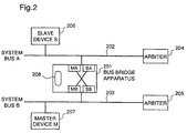
- Figure 2 is a block diagram illustrating a basic construction of a system utilizing a bus bridge apparatus according to a third embodiment.
- Figure 3 is a block diagram illustrating a basic construction of a system utilizing a bus bridge apparatus according to a fourth embodiment.
- Figure 4 is a block diagram illustrating a basic construction of a system utilizing a bus bridge apparatus according to a fourth embodiment.
- Figure 5 is a block diagram illustrating a basic construction of a system utilizing a bus bridge apparatus according to a fifth embodiment.
- Figure 6 is a block diagram illustrating a basic construction of a system utilizing a bus bridge apparatus according to a sixth embodiment.
- Figure 7 is a timing chart for explaining a first operation of the system utilizing the bus bridge apparatus of the sixth embodiment.
- Figure 8 is a timing chart for explaining a second operation of the system utilizing the bus bridge apparatus of the sixth embodiment.
- Figure 9 is a block diagram illustrating a basic construction of a system utilizing a bus bridge apparatus according to a seventh embodiment.
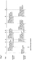
- Figure 10 is a timing chart for explaining a first operation of the system utilizing the bus bridge apparatus of the seventh embodiment.
- Figure 11 is a timing chart for explaining a second operation of the system utilizing the bus bridge apparatus of the seventh embodiment.
- Figure 12 is a diagram illustrating a system in which a conventional bus bridge apparatus is disposed between two independent system buses.
- Figure 1 is a block diagram illustrating a basic construction of a system utilizing a bus bridge apparatus according to a first embodiment of the present invention.
- a bus bridge apparatus 101 is provided with a base address holding means 108, a bus address generating means 109 and master/slave transfer control means 110.
- a system bus A 102 and a system bus B 103 are completely independent of each other.
- An arbiter 104 and a slave bus S 106 are connected to the system bus A 102.
- An arbiter 105 and a slave device M 107 are connected to the system bus B 103.
- both system buses 102 and 103 function independently as a system bus.
- the system so constructed realizes that, between two computer systems, one computer system performs access as if a slave device in the other computer system were a slave device on the former, by disposing a bus bridge apparatus of this embodiment between buses of the two computer systems.
- the bus bridge apparatus 101 has interface functions MA and MB as a bus master, and interface functions SA and SB, as a slave, for the system buses A and B, respectively. Operations of MA, MB, SA, and SB are cooperatively controlled by the master/slave transfer control means 110, in which addresses are previously mapped so that, from the system bus B side, the system bus A is seen as a certain address space.
- the master device M 107 requests bus use right to the arbiter 105 to acquire the right to use the system bus B, and issues the address corresponding to the slave device S 106, thereby starting access to the bus bridge apparatus 101.
- the master/slave transfer control means 110 starts the interface function SB on the system bus B, so that the bus bridge apparatus 101 serves as a slave for the master device M 107, while the means 110 starts the interface function MA on the system bus A for serving as a master device, requests bus use right to the arbiter 104 for acquiring the right to use the system bus A and then becomes a bus master.
- the interface function SB receives addresses from the master device M, and the master/slave transfer control means 110 decides that it is an access to a slave device on the system bus A, the means 110 extracts part representing offset from the received addresses. Based on base addresses held in the base address holding means 108, and the aforesaid offset, the bus address generating means 109 generates an address for an access destination in the slave device S 106.
- the base address holding means 108 is reloadable, and the base address is variable.
- the interface function MA serving as a bus master issues the address generated by the bus address generating means 109 and then starts an access to the slave device S 106.
- Embodiment 1 mutual bus access is realized by retaining the arbitration functions of the independent system buses A and B as they are, without changing system design of the two systems that are independent of each other.
- a system constituted by a bus bridge apparatus of Embodiment 1 is likely to cause time-out. Therefore, a system utilizing a bus bridge apparatus of this embodiment is directed to avoid it.
- the bus bridge apparatus 101 When the master device M 107 attempts to read data from the slave device S 106 through the bus bridge apparatus 101, the bus bridge apparatus 101 requests bus use right to the arbiter 104 in order to be a bus master of the system bus A, however, if the system bus A is presently occupied by another device, the bus bridge apparatus 101 cannot acquire bus use right. For a lengthy wait state, the system bus B is likely to cause time-out. When the bus bridge apparatus 101 decides that the possibility of time-out is high, the apparatus 101 issues an acknowledge signal (RERUN ACKNOWLEDGE) for requesting a rerun of the present access, to the master device M, so that a bus cycle of the system bus B is terminated temporarily.
- RERUN ACKNOWLEDGE acknowledge signal
- the bus bridge apparatus 101 continues to request bus use right to the arbiter 104. If a RERUN ACKNOWLEDGE is issued before acquiring bus use right from the arbiter 104, a bus cycle of the system bus B is completed. Therefore, it is possible to abandon an acquisition request and complete the entire operation.
- a bus cycle of the system bus A is normally completed by performing reading from the slave device S 106, so that the read data is abandoned without inputting to the bus bridge apparatus 101.
- Embodiment 2 mutual bus access is realized by retaining the arbitration functions of the independent system buses A and B, without changing system design of two independent systems being independent of each other.
- the master device M on the other system bus B cannot start a read access, it is possible to avoid time-out.
- time-out on the system bus B is avoided by temporarily accepting write data in a write buffer contained in the bus bridge apparatus 101 to complete a bus cycle of the system bus B, and performing writing to the slave device S some time later.
- FIG. 2 is a block diagram illustrating a basic construction of a system utilizing a bus bridge apparatus according to a third embodiment. Time-out is avoided by employing a bus bridge apparatus of this embodiment.
- a bus bridge apparatus 201 has a bus cycle generating means 208, and is disposed between a system bus A 202 and a system bus B 203.
- An arbiter 204 and a slave device S 206 are connected to the system bus A 202.
- An arbiter 205 and a master device M 207 are connected to the bus B 203.
- the system bus A 202 is a bus in which a bus master having bus use right has the right to access a slave device.
- the bus bridge apparatus 201 When the master device M 207 attempts to access the slave device S 206 through the bus bridge apparatus 201, if the system bus A is occupied by another device, the bus bridge apparatus 201 cannot acquire the right to use the system bus A, so that it continues to request bus use right to the arbiter 204 on the system bus A. For a lengthy waiting state, the system bus B is likely to cause time-out.
- the bus bridge apparatus 201 decides that the system bus B will cause time-out, the apparatus 201 issues a RERUN ACKNOWLEDGE to the master device M 207, to terminate temporarily a bus cycle of the system bus B. During this period, the apparatus 201 continues to request bus use right to the arbiter 204 on the system bus A.
- the bus cycle generating means 208 delays to send a bus cycle start signal, retaining the bus use right. During this period, if occurred again data transfer from a master device on the system bus B to a slave device on the system bus A, the bus cycle generating means 208 releases a pending status and then issues a bus cycle start signal, so that the bus bridge apparatus 201 accesses a target slave device.
- a master device that triggers access is not always the master device M that issued a RERUN ACKNOWLEDGE in the foregoing description.
- Embodiment 3 mutual bus access is realized by retaining the arbitration functions of the independent system buses A and B, without changing system design of two independent systems being independent of each other.
- the master device M on the other system bus B cannot start a read access, it is possible to avoid time-out.
- bus use right In a bus in which the arbiter 204 takes the bus use right given to a master device and gives it to another master device, if bus use right is taken from the arbiter 204 while the bus bridge apparatus 201 delays to issue a bus cycle start instruction, retaining the bus use right, the bus cycle generating means 208 is reset to an idle state, so that the entire operation is completed.
- the reason for this is that the master device M does not always win a bus arbitration on the system bus B against other master devices; and that, even if the master device M acquires the right to use the system bus B, when it accesses the bus bridge apparatus, a RERUN ACKNOWLEDGE is likely to be issued depending on the condition of the system bus A.
- a system utilizing a bus bridge apparatus solves such problems, and enables the master device M on the system bus B to access the slave device S of the system bus A.
- FIG. 3 is a diagram illustrating a basic construction of a system in this embodiment.
- a bus bridge apparatus 301 has a transfer buffer 308 and a device name storing means 309.
- An arbiter 304 and a slave device S 306 are connected to a system bus A 302.
- An arbiter 305, a master device M 307 and a master device E 310 are connected to a system bus B 303.
- the bus bridge apparatus 301 issues a RERUN ACKNOWLEDGE to the master device M, to temporarily terminates a bus cycle of the system bus B.
- the name of the master device M 307 is stored in the device name storing means 309. In order to store the name, for example, there are prepared bits as many as master devices so that one bit corresponds to one master device on the system bus B, thereafter, the bits are made valid whenever they are stored.
- a signal that indicates the acquisition of the right to use the system bus B, or employed ID number for a bus in which a master device issues ID number along with an address.
- bus bridge apparatus 301 Even after the bus bridge apparatus 301 issues a RERUN ACKNOWLEDGE to the master device M 307, it attempts to be a bus master of the system bus A. Assume now that the arbiter 304 on the system bus A is arbitrating a bus by round robin scheduling, and the number of master devices on the system bus A is X. If only the bus bridge apparatus 301 continues to issue a bus acquisition request, it wins at the Xth arbitration in the worst case, thus obtaining the right to use the system bus B. As a result, the bus bridge apparatus 301 reads, from the slave device S 306, data to be given to the master device M 307, and then inputs it to the transfer buffer 308, so that a bus cycle of the system bus A is terminated.
- each master bus is issuing a request for acquiring bus use right to the arbiter 305.
- the master device E 310 wins an arbitration to access the bus bridge apparatus 301.
- the bus bridge apparatus 301 identifies which master device won the arbitration and then checks with the content of the device name storing means 309.
- the apparatus 301 decides it is mismatch and then issues a RERUN ACKNOWLEDGE to the master device E.
- the arbiter 305 is also arbitrating a bus by round robin scheduling, and the number of master devices on the system bus B is Y. Therefore, the master device M will win at the Yth arbitration in the worse case, to obtain the right to use the system bus B.
- the master device M wins the arbitration and retries to access the bus bridge apparatus 301 it is decided to be match with the content of the device name storing means 309. Then, it is decided whether the aforesaid reading data from the slave device S to the transfer buffer 308 is completed. If not completed, the bus bridge apparatus 301 issues again a RERUN ACKNOWLEDGE to the master device M. If completed, the apparatus 301 gives data being read in the transfer buffer 308 to the master device M, at the same time, clears the content stored in the device name storing means, thereby completing the entire operation.
- the case requiring the longest time to complete the transfer is where the bus bridge apparatus 301 wins the Xth arbitration on the system bus A and then inputs data to the transfer buffer 308, thereafter, the master device M wins the Yth arbitration on the system bus B and reissues a read instruction.
- the sum of time required in the respective processing is the maximum wait time in this read access.
- the transfer buffer 308 is employed as a write buffer and write data is temporarily accepted by the transfer buffer 308 for terminating a bus cycle of the system bus B, and that data is later written to the slave device S.
- Embodiment 4 mutual bus access is realized by retaining the arbitration functions of the independent system buses A and B, without changing system design of two independent systems being independent of each other. Further, even when the system bus A having the slave device S to which access is desired, is busy, and therefore, the master device M on the other system bus B cannot start a read access, it is possible to avoid time-out. Furthermore, the master device M surely performs a read access to the slave device S within a given time.
- FIG. 4 is a block diagram illustrating a system to which a bus bridge apparatus of Embodiment 4 is utilized.
- a bus bridge apparatus 401 has a first transfer buffer 408, a first device name storing means 409, a second transfer buffer 412 and a second device name storing means 413.
- An arbiter 404, a slave device S1 406 and a master device M2 411 are connected to a system bus A 402.
- An arbiter 405, a master device M1 407 and a slave device S2 410 are connected to a system bus B 403.
- a system utilizing a bus bridge apparatus surely accesses the slave device S within a given time.
- This embodiment is particularly related to a case where the system bus A is a bus in which a bus master succeeded in acquiring bus use right has the right to access a slave device.
- FIG. 5 is a block diagram illustrating a basic construction of a system utilizing a bus bridge apparatus of this embodiment.
- a bus bridge apparatus 501 has a bus cycle generating means 508 and a device name storing means 509.
- An arbiter 504 and a slave device S 506 are connected to a system bus A 502.
- An arbiter 505, a master device M 507 and a master device E 510 are connected to a system bus B 503.
- the bus bridge apparatus 501 is provided with the bus cycle generating means 508 that delays to issue a bus cycle start signal while retaining bus use right, as described in Embodiment 3, and the device name storing means 509 as described in Embodiment 4.
- the bus bridge apparatus 501 issues a RERUN ACKNOWLEDGE to the master device M 507, thus terminating a bus cycle temporarily.
- the name of the master device M 507 is stored in the device name storing means 509. During this time, the bus bridge apparatus 501 continues to request bus use right to the arbiter 504 on the system bus A.
- each master device On the system bus B, each master device is issuing a request for acquiring bus use right to the arbiter 505 on the system bus B.
- the master device E 510 wins an arbitration and then accesses the bus bridge apparatus 501.
- the bus bridge apparatus 501 identifies which master device won the arbitration and then checks with the content of the device name storing means 509.
- the content of the device name storing means 509 is the master device M, it is decided to be mismatch when the master device M accesses the bus bridge apparatus 501, and then issued a RERUN ACKNOWLEDGE to the master device E.
- the master device M wins an arbitration and retries to access the bus bridge apparatus 501, it is decided that it matches with the content of the device name storing means 509. At this time, it is decided whether the bus cycle generating means 508 has obtained the right to use the system bus A. If not yet, the bus bridge apparatus 501 issues a RERUN ACKNOWLEDGE to the master device M. If already obtained, the bus cycle generating means 508 releases a temporary pending state to issue a bus cycle start signal, and accesses the master device M through the bus bridge apparatus 501 and, at the same time, clears the content stored in the device name storing means 509, thereby completing the entire operation.
- bus use right In the cases where the arbiter 504 takes the bus use right given to the master device and then gives it to another master device, if bus use right is taken from the arbiter 504 while the bus bridge apparatus 501 delays to issue a bus cycle start instruction, retaining the right to use the system bus A, the bus bridge apparatus 501 issues again a bus acquisition request to the arbiter 504. Upon the receipt of bus use right, the apparatus delays again to issue a bus cycle start signal.
- Embodiment 5 mutual bus access is realized by retaining the arbitration functions of the independent system buses A and B, without changing system design of two independent systems being independent of each other. Further, even if the system bus A having the slave device S to which access is desired, is busy, and therefore, the master device M on the other system bus B cannot start a read access, it is possible to avoid time-out. Furthermore, the master device M surely performs a read access to the slave device S within a given time.
- a bus bridge apparatus avoids a deadlock state without containing a bus arbiter function therein, when a master/slave transfer and an inter-slave transfer are performed at the same time, between system buses A and B that are completely independent of each other.
- FIG. 6 is a diagram for explaining a construction of a bus bridge apparatus of this embodiment and devices connected thereto.
- Data holding means MS 616 temporarily holds transferred data when transferring data between a slave device on the system bus A 609 and a master device on the system bus B 610 (i.e., master/slave transfer).
- Data holding means SS 617 temporarily holds transferred data when transferring data between a slave device on the system bus A 609 and a slave device on the system bus B 610 (i.e., inter-slave transfer).
- Inter-slave transfer control means 619 controls data transfer in the inter-slave transfer.
- Transfer control means 620 arbitrates between the master/slave transfer and the inter-slave transfer.
- Transfer source address holding means 621 holds the address of a transfer source slave in the inter-slave transfer, and its initial value is set by the master device E 613 through the interface function SB 604, and then incremented by the inter-slave transfer control means 619 during data transfer.
- Transfer destination address holding means 622 holds the address of a transfer destination slave in the inter-slave transfer, and its initial value is set by the master device E 613 through the interface function SB 604, and then incremented by the inter-slave transfer control means 619 during data transfer.
- Transfer size holding means 623 holds the size of data transfer in the inter-slave transfer, and its initial value is set by the master device E 613 through the interface function SB 604, and then decremented by the inter-slave transfer control means 619 during data transfer.
- Transfer direction holding means 624 holds the direction of data transfer in the inter-slave transfer, a direction is set before data transfer, by the master device E 613 through the interface function SB 604. For “0”, data transfer from the system bus A 609 to the system bus B 610 is executed. For “1”, data transfer from the system bus B 610 to the system bus A 609 is executed.
- Figure 8 is a diagram showing operations of the system buses A, B in Operation II.
- the master device E 613 writes C1 that is a transfer source address, to the transfer source address holding means 621, writes "64" that is a transfer size, to the transfer size holding means 623, and writes "0" as a transfer direction (transfer from the system bus A to B), to the transfer direction holding means 624, through the interface function SB 604, respectively.
- a transfer start instruction is given to the inter-slave transfer control means 619 through the interface function SB 604, whereby the bus bridge apparatus starts the inter-slave transfer from the slave device C to the slave device D.
- the inter-slave transfer control means 619 instructs the interface function MA 601 to serve as a bus master of the system bus A, in order to read 32 bytes data from the address C1 of the slave device C and then store it in the data holding means SS 617.
- the reason why the transfer size at the moment is 32 bytes, is that the maximum size per bus cycle on the system bus A is 32 bytes.
- the interface function MA 601 issues a bus acquisition request to the bus arbiter A 614, in order to be a master of the system bus A.
- the bus arbiter A 614 gives bus use right to the bus bridge apparatus.
- the interface function MA 601 becomes a bus master of the system bus A and reads 32 bytes data from the address C1 of the slave device C, thereby storing it in the data holding means SS 617.
- the master device E starts a bus cycle for writing 4 bytes data possessed by itself to a region led by the address C2 of the slave device C, by utilizing the master/slave transfer in the bus bridge apparatus.
- the master/slave transfer control means 608 issues an operation start instruction to the interface function SB 601.
- the SB 601 receives 4 bytes write data from the master device E, and holds it in the data holding means SS 617, thus completing the operation at time t4. Accordingly, the bus cycle of the master device E on the system bus B is completed.
- the master/slave transfer control means 608 issues an operation start instruction to the interface function MA 601. At this time, the MA 601 is being used for the inter-slave transfer, resulting in a wait state.
- the inter-slave transfer control means 619 instructs the MA 602 to serve as a bus master of the system bus B and transfer the 32 bytes data stored in the data holding means SS 617 to the address D1 of the slave device D.
- the MB 602 issues a bus acquisition request to the bus arbiter B 615, in order to be a bus master of the system bus B.
- the bus arbiter B 615 gives bus use right to the bus bridge apparatus.
- the MB 602 serves as a bus master of the system us B, and then transfers the 32 bytes data stored in the data holding means SS 617 to the address D1 of the slave device D.
- this transfer is completed.
- the master/slave transfer control means 608 that has been in a wait state, is in an operation state and then issues again an operation start instruction to the MA 601. Then, the MA 601 issues a bus acquisition request to the bus arbiter A 614, in order to be a bus master of the system bus A. At this time, since the system bus A is not being used, the bus arbiter A 614 gives bus use right to the bus bridge apparatus. As a result, the MA 601 becomes a bus master of the system bus A and then transfers 4 bytes data held in the data holding means SS 617 to the address C2 of the slave C, whereby the transfer is completed at time t6.
- the 32 bytes data stored in the means SS 617 is transferred to an address D1+32 of the slave device D.
- the value of the transfer source address holding means 621 is incremented by 32 and results in C1+64
- that of the transfer destination address holding means 622 is incremented by 32 and results in D1+64
- that of the transfer size holding means 623 is decremented by 32 and results in 0, thus completing the inter-slave transfer.
- Embodiment 6 when the master/slave transfer and the inter-slave transfer are performed at the same time, a deadlock state is avoided by including data holding means MS and SS that operate independently for a specific use, without containing a bus arbiter function in a bus bridge apparatus.
- a bus bridge apparatus avoids a deadlock state when a master/slave transfer and an inter-slave transfer are performed at the same time, between system buses A and B that are completely independent of each other, by providing only one data holding means, without containing a bus arbiter function in a bus bridge apparatus.
- FIG. 9 is a diagram for explaining a construction of a bus bridge apparatus of this embodiment and devices to be connected thereto.
- Data holding means 916 temporarily holds transferred data in performing data transfer between a slave device on the system bus A 909 and a master device on the system bus B 910 (i.e., master/slave transfer) and, in performing data transfer between a slave device on the system bus A 909 and a slave device on the system bus B 910 (i.e., inter-slave transfer).
- Figure 11 is a diagram showing operations of the system buses A, B in operation II.
- the master device E 913 writes C1 that is a transfer source address, to the transfer source address holding means 921, writes "64" that is a transfer size, to the transfer size holding means 923, and writes "0" as a transfer direction (transfer from the system bus A to B), to the transfer direction holding means 924, through the interface function SB 904, respectively.
- a transfer start instruction is given to the inter-slave transfer control means 919 through the interface function SB 904, whereby the bus bridge apparatus starts the inter-slave transfer from the slave device C to the slave device D.
- the inter-slave transfer control means 919 instructs the interface function MA 901 to serve as a bus master of the system bus A, in order to read 32 bytes data from the address C1 of the slave device C and then store it in the data holding means SS 916.
- the reason why a transfer size at the moment is 32 bytes, is that the maximum size per bus cycle in the system bus A is 32 bytes.
- the interface function MA 901 issues a bus acquisition request to the bus arbiter 914, in order to be a master of the system bus A.
- the bus arbiter 914 gives bus use right to the bus bridge apparatus.
- the interface function MA 901 becomes a bus master of the system bus A and reads 32 bytes data from the address C1 of the slave device C, thereby storing it in the data holding means SS 916.
- the master device E starts a bus cycle for writing 4 bytes data possessed by itself to a region led by the address C2 of the slave device C, by utilizing the master/slave transfer in the bus bridge apparatus.
- the master/slave transfer control means 908 attempts to start operation, at the moment, the data holding means 916 is being used for the inter-slave transfer, resulting in a wait state.
- the inter-slave transfer control means 919 instructs the MA 902 to serve as a bus master of the system bus B and then transfer the 32 bytes data stored in the data holding means SS 916 to the address D1 of the slave device D. Then, the MB 902 issues a bus acquisition request to the bus arbiter B 915, in order to be a bus master of the system bus B.
- the MB 902 is in a wait sate until it acquires bus use right.
- the transfer control means 920 abandons data stored in the data holding means 916 and gives the right to use the data holding means 916 to the master/slave transfer control means 908.
- the transfer control means 920 informs the inter-slave transfer control means 919 that the data transfer is canceled.
- the master/slave transfer control means 908 resumes the operation and then gives an operation instruction to the interface function MA 901.
- the MA 901 receives 4 bytes data from the master device E and holds it in the data holding means 916, thus completing the operation at time t5.
- the bus cycle of the master device E on the system bus B is completed.
- the master/slave transfer control means 908 issues an operation start instruction to the interface function MA 901.
- the MA 901 serves as a bus master of the system bus A and transfers the 4 bytes data held in the data holding means 916 to the address C2 of the slave C. This transfer is completed at time t6.
- the transfer control means 920 instructs the inter-slave transfer control means 919 to rerun data transfer operation.
- the means 919 instructs again the interface function MA 901 to serve as a bus master of the system bus A, to read 32 bytes data from the address C1 of the slave device C, and then store it to the data holding means 916.
- the MA 901 serves as a bus master of the system bus A, so that the 32 bytes data is read from the address C1 of the slave device C, and then stored in the data holding means 916.
- the inter-slave transfer control means 919 instructs the interface function MB 902 to serve as a bus master of the system bus B and transfer the 32 bytes data stored in the data holding means 916 to the address D1 of the slave device D.
- the MB 902 serves as a bus master of the system bus B to transfer 32 bytes data stored in the data holding means 916 to the address D1 of the slave device D.
- the 32 bytes data stored in the means 916 is transferred to an address D1+32 of the slave device D.
- the value of the transfer source address holding means 921 is incremented by 32 and results in C1+64
- that of the transfer destination address holding means 922 is incremented by 32 and results in D1+64
- that of the transfer size holding means 923 is decremented by 32 and results in 0, thus completing the inter-slave transfer.
- Embodiment 7 in a case where a deadlock state is likely to occur when a master/slave transfer and an inter-slave transfer are performed at the same time by data transfer control means, with only one data holding means, it is possible to avoid a deadlock state by abandoning data that has been transferred to the data holding means by the inter-slave transfer, and preferentially executing the master/slave transfer, without containing a bus arbiter function in a bus bridge apparatus.
Landscapes
- Engineering & Computer Science (AREA)
- Theoretical Computer Science (AREA)
- General Engineering & Computer Science (AREA)
- Physics & Mathematics (AREA)
- General Physics & Mathematics (AREA)
- Computer Hardware Design (AREA)
- Bus Control (AREA)
- Small-Scale Networks (AREA)
- Data Exchanges In Wide-Area Networks (AREA)
Applications Claiming Priority (3)
| Application Number | Priority Date | Filing Date | Title |
|---|---|---|---|
| JP8156781A JPH103447A (ja) | 1996-06-18 | 1996-06-18 | バスブリッジ装置 |
| JP15678196 | 1996-06-18 | ||
| JP156781/96 | 1996-06-18 |
Publications (3)
| Publication Number | Publication Date |
|---|---|
| EP0814408A2 true EP0814408A2 (fr) | 1997-12-29 |
| EP0814408A3 EP0814408A3 (fr) | 2002-03-27 |
| EP0814408B1 EP0814408B1 (fr) | 2003-01-29 |
Family
ID=15635179
Family Applications (1)
| Application Number | Title | Priority Date | Filing Date |
|---|---|---|---|
| EP97109826A Expired - Lifetime EP0814408B1 (fr) | 1996-06-18 | 1997-06-17 | Appareil de passerelle de bus |
Country Status (4)
| Country | Link |
|---|---|
| US (1) | US5978879A (fr) |
| EP (1) | EP0814408B1 (fr) |
| JP (1) | JPH103447A (fr) |
| DE (1) | DE69718710T2 (fr) |
Cited By (4)
| Publication number | Priority date | Publication date | Assignee | Title |
|---|---|---|---|---|
| WO1999050753A1 (fr) * | 1998-03-31 | 1999-10-07 | Lsi Logic Corporation | Procede et appareil servant a arbitrer l'acces a plusieurs bus dans un systeme de traitement de donnees |
| EP1187030A1 (fr) * | 2000-09-08 | 2002-03-13 | Texas Instruments Inc. | Système de bus à transactions multiples |
| EP1148425A3 (fr) * | 2000-04-18 | 2006-02-22 | Fujitsu Siemens Computers GmbH | Dispositif de traitement de données comprenant un circuit pour relier un premier bus de communication à un deuxième bus de communication |
| US7177966B2 (en) * | 2004-03-02 | 2007-02-13 | Renesas Technology Corp. | Microcomputer minimizing influence of bus contention |
Families Citing this family (12)
| Publication number | Priority date | Publication date | Assignee | Title |
|---|---|---|---|---|
| US6223237B1 (en) * | 1998-07-07 | 2001-04-24 | Adaptive Systems, Inc. | Expandable communications bus |
| US6636927B1 (en) * | 1999-09-24 | 2003-10-21 | Adaptec, Inc. | Bridge device for transferring data using master-specific prefetch sizes |
| US6976108B2 (en) * | 2001-01-31 | 2005-12-13 | Samsung Electronics Co., Ltd. | System on a chip having a system bus, an external bus, and a bus arbiter with programmable priorities for both buses, software, and method for assigning programmable priorities |
| TW514791B (en) * | 2001-05-28 | 2002-12-21 | Via Tech Inc | Structure, method and related control chip for accessing device of computer system with system management bus |
| FI20011257A0 (fi) * | 2001-06-13 | 2001-06-13 | Nokia Corp | Menetelmä väylän mukauttamiseksi ja väylä |
| KR101034494B1 (ko) * | 2004-02-11 | 2011-05-17 | 삼성전자주식회사 | 개방형 코어 프로토콜을 기반으로 하는 버스 시스템 |
| JP2005346513A (ja) * | 2004-06-04 | 2005-12-15 | Renesas Technology Corp | 半導体装置 |
| JP4260720B2 (ja) * | 2004-10-27 | 2009-04-30 | 日本テキサス・インスツルメンツ株式会社 | バス制御装置 |
| KR100631202B1 (ko) * | 2005-01-11 | 2006-10-04 | 삼성전자주식회사 | Cdma 버스를 이용한 원칩 시스템 및 그의 데이터전송방법 |
| US7634611B2 (en) * | 2006-03-17 | 2009-12-15 | Agilent Technologies, Inc. | Multi-master, chained two-wire serial bus |
| EP2063542B1 (fr) * | 2006-06-16 | 2013-06-12 | Sharp Kabushiki Kaisha | Dispositif de création de données, procédé de création de données, station de base, station mobile, procédé de détection de synchronisation, procédé d'identification de secteur, procédé de détection d'informations, et système de communication mobile |
| JP2008118211A (ja) * | 2006-10-31 | 2008-05-22 | Toshiba Corp | データ転送装置及びデータ転送方法 |
Family Cites Families (5)
| Publication number | Priority date | Publication date | Assignee | Title |
|---|---|---|---|---|
| US4257099A (en) * | 1975-10-14 | 1981-03-17 | Texas Instruments Incorporated | Communication bus coupler |
| JPH02178752A (ja) * | 1988-12-29 | 1990-07-11 | Nissin Electric Co Ltd | システムバスのエクステンダ |
| JPH02178753A (ja) * | 1988-12-29 | 1990-07-11 | Nissin Electric Co Ltd | システムバスのエクステンダ |
| US5717873A (en) * | 1993-09-30 | 1998-02-10 | Intel Corporation | Deadlock avoidance mechanism and method for multiple bus topology |
| CA2160499A1 (fr) * | 1994-11-30 | 1996-05-31 | Patrick Maurice Bland | Pont reliant les divers bus d'un systeme a bus a capacites d'adressage memoire differentes muni d'un dispositif de reaffectation des segments de memoire dans sa topographie memoire |
-
1996
- 1996-06-18 JP JP8156781A patent/JPH103447A/ja active Pending
-
1997
- 1997-06-17 US US08/877,208 patent/US5978879A/en not_active Expired - Fee Related
- 1997-06-17 DE DE69718710T patent/DE69718710T2/de not_active Expired - Fee Related
- 1997-06-17 EP EP97109826A patent/EP0814408B1/fr not_active Expired - Lifetime
Cited By (6)
| Publication number | Priority date | Publication date | Assignee | Title |
|---|---|---|---|---|
| WO1999050753A1 (fr) * | 1998-03-31 | 1999-10-07 | Lsi Logic Corporation | Procede et appareil servant a arbitrer l'acces a plusieurs bus dans un systeme de traitement de donnees |
| US6260093B1 (en) | 1998-03-31 | 2001-07-10 | Lsi Logic Corporation | Method and apparatus for arbitrating access to multiple buses in a data processing system |
| EP1148425A3 (fr) * | 2000-04-18 | 2006-02-22 | Fujitsu Siemens Computers GmbH | Dispositif de traitement de données comprenant un circuit pour relier un premier bus de communication à un deuxième bus de communication |
| EP1187030A1 (fr) * | 2000-09-08 | 2002-03-13 | Texas Instruments Inc. | Système de bus à transactions multiples |
| US6775732B2 (en) | 2000-09-08 | 2004-08-10 | Texas Instruments Incorporated | Multiple transaction bus system |
| US7177966B2 (en) * | 2004-03-02 | 2007-02-13 | Renesas Technology Corp. | Microcomputer minimizing influence of bus contention |
Also Published As
| Publication number | Publication date |
|---|---|
| US5978879A (en) | 1999-11-02 |
| JPH103447A (ja) | 1998-01-06 |
| EP0814408B1 (fr) | 2003-01-29 |
| DE69718710T2 (de) | 2003-10-23 |
| EP0814408A3 (fr) | 2002-03-27 |
| DE69718710D1 (de) | 2003-03-06 |
Similar Documents
| Publication | Publication Date | Title |
|---|---|---|
| EP0814408B1 (fr) | Appareil de passerelle de bus | |
| US6493776B1 (en) | Scalable on-chip system bus | |
| US5870625A (en) | Non-blocking memory write/read mechanism by combining two pending commands write and read in buffer and executing the combined command in advance of other pending command | |
| US5335329A (en) | Apparatus for providing DMA functionality to devices located in a bus expansion chassis | |
| US6189062B1 (en) | Apparatus and method for address translation in bus bridge devices | |
| JP2004171209A (ja) | 共有メモリデータ転送装置 | |
| JPH02289017A (ja) | コンピユータシステム内でデータ転送方法 | |
| CA2007737C (fr) | Operations de transfert de donnees entre deux bus asynchrones | |
| KR20020009823A (ko) | 버스 시스템 및 그 버스 중재방법 | |
| EP1187029B1 (fr) | Mise en oeuvre d'un arbitre PCI avec schéma de priorité dynamique | |
| US7203781B2 (en) | Bus architecture with primary bus and secondary or slave bus wherein transfer via DMA is in single transfer phase engagement of primary bus | |
| JP2996179B2 (ja) | Pciバス・システム | |
| US6247089B1 (en) | Efficient data loading scheme to minimize PCI bus arbitrations delays and wait states | |
| US20100153610A1 (en) | Bus arbiter and bus system | |
| JP2885640B2 (ja) | データバス転送方法 | |
| JPH0844661A (ja) | 情報処理装置 | |
| JPH09128324A (ja) | データ転送制御装置およびデータ転送制御方法 | |
| JPH0895899A (ja) | Dma転送制御装置 | |
| JP2000029823A (ja) | バスアクセス制御回路 | |
| JP2001318906A (ja) | マルチプロセッサ装置 | |
| JPH08339353A (ja) | マルチプロセッサ装置 | |
| JP2001075826A (ja) | 並列計算機における高効率セマフォ処理方式 | |
| JPH06332851A (ja) | データ転送方式 | |
| JPH11338815A (ja) | バスの転送効率低下を回避することができるブリッジ装置 | |
| JPS6341973A (ja) | マルチプロセツサシステム |
Legal Events
| Date | Code | Title | Description |
|---|---|---|---|
| PUAI | Public reference made under article 153(3) epc to a published international application that has entered the european phase |
Free format text: ORIGINAL CODE: 0009012 |
|
| AK | Designated contracting states |
Kind code of ref document: A2 Designated state(s): AT BE CH DE DK ES FI FR GB GR IE IT LU MC NL PT SE Kind code of ref document: A2 Designated state(s): DE FR GB |
|
| RIN1 | Information on inventor provided before grant (corrected) |
Inventor name: YUGAWA, TAIHEI Inventor name: OCHIAI, TOSHIYUKI Inventor name: HARUMOTO, HIDEAKI |
|
| PUAL | Search report despatched |
Free format text: ORIGINAL CODE: 0009013 |
|
| AK | Designated contracting states |
Kind code of ref document: A3 Designated state(s): AT BE CH DE DK ES FI FR GB GR IE IT LI LU MC NL PT SE |
|
| 17P | Request for examination filed |
Effective date: 20020411 |
|
| GRAH | Despatch of communication of intention to grant a patent |
Free format text: ORIGINAL CODE: EPIDOS IGRA |
|
| GRAH | Despatch of communication of intention to grant a patent |
Free format text: ORIGINAL CODE: EPIDOS IGRA |
|
| GRAA | (expected) grant |
Free format text: ORIGINAL CODE: 0009210 |
|
| AKX | Designation fees paid |
Free format text: DE FR GB |
|
| RBV | Designated contracting states (corrected) |
Designated state(s): DE FR GB |
|
| AK | Designated contracting states |
Designated state(s): DE FR GB |
|
| REG | Reference to a national code |
Ref country code: GB Ref legal event code: FG4D |
|
| REG | Reference to a national code |
Ref country code: IE Ref legal event code: FG4D |
|
| REF | Corresponds to: |
Ref document number: 69718710 Country of ref document: DE Date of ref document: 20030306 Kind code of ref document: P |
|
| ET | Fr: translation filed | ||
| PLBE | No opposition filed within time limit |
Free format text: ORIGINAL CODE: 0009261 |
|
| STAA | Information on the status of an ep patent application or granted ep patent |
Free format text: STATUS: NO OPPOSITION FILED WITHIN TIME LIMIT |
|
| 26N | No opposition filed |
Effective date: 20031030 |
|
| REG | Reference to a national code |
Ref country code: IE Ref legal event code: MM4A |
|
| PGFP | Annual fee paid to national office [announced via postgrant information from national office to epo] |
Ref country code: DE Payment date: 20080626 Year of fee payment: 12 |
|
| PGFP | Annual fee paid to national office [announced via postgrant information from national office to epo] |
Ref country code: FR Payment date: 20080617 Year of fee payment: 12 |
|
| PGFP | Annual fee paid to national office [announced via postgrant information from national office to epo] |
Ref country code: GB Payment date: 20080618 Year of fee payment: 12 |
|
| GBPC | Gb: european patent ceased through non-payment of renewal fee |
Effective date: 20090617 |
|
| REG | Reference to a national code |
Ref country code: FR Ref legal event code: ST Effective date: 20100226 |
|
| PG25 | Lapsed in a contracting state [announced via postgrant information from national office to epo] |
Ref country code: FR Free format text: LAPSE BECAUSE OF NON-PAYMENT OF DUE FEES Effective date: 20090630 |
|
| PG25 | Lapsed in a contracting state [announced via postgrant information from national office to epo] |
Ref country code: GB Free format text: LAPSE BECAUSE OF NON-PAYMENT OF DUE FEES Effective date: 20090617 |
|
| PG25 | Lapsed in a contracting state [announced via postgrant information from national office to epo] |
Ref country code: DE Free format text: LAPSE BECAUSE OF NON-PAYMENT OF DUE FEES Effective date: 20100101 |