EP0817527A2 - Restauration du canal D du RNIS sans perte de données de signalisation ou en paquets - Google Patents
Restauration du canal D du RNIS sans perte de données de signalisation ou en paquets Download PDFInfo
- Publication number
- EP0817527A2 EP0817527A2 EP97304221A EP97304221A EP0817527A2 EP 0817527 A2 EP0817527 A2 EP 0817527A2 EP 97304221 A EP97304221 A EP 97304221A EP 97304221 A EP97304221 A EP 97304221A EP 0817527 A2 EP0817527 A2 EP 0817527A2
- Authority
- EP
- European Patent Office
- Prior art keywords
- signaling channel
- software
- physical
- link
- channel
- Prior art date
- Legal status (The legal status is an assumption and is not a legal conclusion. Google has not performed a legal analysis and makes no representation as to the accuracy of the status listed.)
- Granted
Links
Images



Classifications
-
- H—ELECTRICITY
- H04—ELECTRIC COMMUNICATION TECHNIQUE
- H04Q—SELECTING
- H04Q3/00—Selecting arrangements
- H04Q3/0016—Arrangements providing connection between exchanges
- H04Q3/0025—Provisions for signalling
-
- H—ELECTRICITY
- H04—ELECTRIC COMMUNICATION TECHNIQUE
- H04J—MULTIPLEX COMMUNICATION
- H04J3/00—Time-division multiplex systems
- H04J3/02—Details
- H04J3/12—Arrangements providing for calling or supervisory signals
-
- H—ELECTRICITY
- H04—ELECTRIC COMMUNICATION TECHNIQUE
- H04Q—SELECTING
- H04Q11/00—Selecting arrangements for multiplex systems
- H04Q11/04—Selecting arrangements for multiplex systems for time-division multiplexing
- H04Q11/0428—Integrated services digital network, i.e. systems for transmission of different types of digitised signals, e.g. speech, data, telecentral, television signals
- H04Q11/0435—Details
- H04Q11/0457—Connection protocols
-
- H—ELECTRICITY
- H04—ELECTRIC COMMUNICATION TECHNIQUE
- H04Q—SELECTING
- H04Q2213/00—Indexing scheme relating to selecting arrangements in general and for multiplex systems
- H04Q2213/1305—Software aspects
-
- H—ELECTRICITY
- H04—ELECTRIC COMMUNICATION TECHNIQUE
- H04Q—SELECTING
- H04Q2213/00—Indexing scheme relating to selecting arrangements in general and for multiplex systems
- H04Q2213/13141—Hunting for free outlet, circuit or channel
-
- H—ELECTRICITY
- H04—ELECTRIC COMMUNICATION TECHNIQUE
- H04Q—SELECTING
- H04Q2213/00—Indexing scheme relating to selecting arrangements in general and for multiplex systems
- H04Q2213/13166—Fault prevention
-
- H—ELECTRICITY
- H04—ELECTRIC COMMUNICATION TECHNIQUE
- H04Q—SELECTING
- H04Q2213/00—Indexing scheme relating to selecting arrangements in general and for multiplex systems
- H04Q2213/13167—Redundant apparatus
-
- H—ELECTRICITY
- H04—ELECTRIC COMMUNICATION TECHNIQUE
- H04Q—SELECTING
- H04Q2213/00—Indexing scheme relating to selecting arrangements in general and for multiplex systems
- H04Q2213/13176—Common channel signaling, CCS7
-
- H—ELECTRICITY
- H04—ELECTRIC COMMUNICATION TECHNIQUE
- H04Q—SELECTING
- H04Q2213/00—Indexing scheme relating to selecting arrangements in general and for multiplex systems
- H04Q2213/13204—Protocols
-
- H—ELECTRICITY
- H04—ELECTRIC COMMUNICATION TECHNIQUE
- H04Q—SELECTING
- H04Q2213/00—Indexing scheme relating to selecting arrangements in general and for multiplex systems
- H04Q2213/13209—ISDN
-
- H—ELECTRICITY
- H04—ELECTRIC COMMUNICATION TECHNIQUE
- H04Q—SELECTING
- H04Q2213/00—Indexing scheme relating to selecting arrangements in general and for multiplex systems
- H04Q2213/13216—Code signals, frame structure
-
- H—ELECTRICITY
- H04—ELECTRIC COMMUNICATION TECHNIQUE
- H04Q—SELECTING
- H04Q2213/00—Indexing scheme relating to selecting arrangements in general and for multiplex systems
- H04Q2213/13352—Self-routing networks, real-time routing
-
- Y—GENERAL TAGGING OF NEW TECHNOLOGICAL DEVELOPMENTS; GENERAL TAGGING OF CROSS-SECTIONAL TECHNOLOGIES SPANNING OVER SEVERAL SECTIONS OF THE IPC; TECHNICAL SUBJECTS COVERED BY FORMER USPC CROSS-REFERENCE ART COLLECTIONS [XRACs] AND DIGESTS
- Y10—TECHNICAL SUBJECTS COVERED BY FORMER USPC
- Y10S—TECHNICAL SUBJECTS COVERED BY FORMER USPC CROSS-REFERENCE ART COLLECTIONS [XRACs] AND DIGESTS
- Y10S370/00—Multiplex communications
- Y10S370/901—Wide area network
- Y10S370/902—Packet switching
- Y10S370/903—Osi compliant network
- Y10S370/904—Integrated Services Digital Network, ISDN
Definitions
- This invention relates to telecommunication switching systems having a plurality of switching nodes, and, in particular, to the rapid backup of a signaling channel interconnecting two of the switch nodes.
- the problem with the utilization of the secondary D channel in accordance with the specifications is that the primary D channel must time out which takes approximately 25 to 30 seconds before the process is started to utilize the secondary D channel. Because of this delay, all calls that were in transit (e. g., being set up) or performing some feature operation must be terminated. In addition, any data call being performed on a logical link of the primary D channel must be terminated.
- the primary PRI link may be disabled.
- One reason is that the primary PRI link is a wired link that has been cut accidentally.
- a second reason is that in a highly distributed system such as illustrated in U. S. Patent 5,390,242 it is necessary to add and remove PRI links interconnecting switch nodes. At present, if calls are not to be terminated, it is necessary to wait until there are no calls being communicated on any of the links making up the FAS group. This is often done by indicating that each of the links is out of service. In general, this requires field personnel to work during the early morning hours when there is little activity on the system.
- a first physical object is established to control a physical protocol on the primary signaling channel
- a second physical object is established to control the physical protocol on the secondary signaling channel.
- a single software object is established to always control the first layer of software protocol on the common signaling channel whether that is the primary signaling channel or secondary signaling channel.
- information for the common signaling channel is routed from the second physical object to the software object, thereby preserving the common signaling channel.
- a first physical protocol identifier is assigned to the first physical object
- a second physical protocol identifier is assigned to the second physical object
- a first layer of software protocol identifier is assigned to the software object.
- the procedure for routing from the second physical object to the software object involves identifying the second physical protocol identifier with the first layer of software protocol identifier. Also, within the ISDN protocol, the first and second physical protocol identifiers are termination endpoint identifiers, and the first layer of software protocol identifier is a connection endpoint suffix.
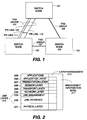
- FIG. 1 shows a telecommunication switching system having a plurality of switch nodes 101, 102, and 103.
- the switch nodes of FIG. 1 function as an integrated system to provide telecommunication services such as those provided by an individual or a network of AT&T Definity® Generic 2 Communications Systems.
- the switch nodes are shown as being interconnected by FAS groups of PRI links. Each FAS group comprises a plurality of PRI links such as PRI links 109 through 112 of FAS group 104.
- the switch nodes of FIG. 1 are arranged in a node hierarchy with switch node 101 being the highest switch node of the node hierarchy. The manner in which the node hierarchy initialization, and dialing plan initiationization are performed is described in detail in U. S. Patent 5,386,466 which is hereby incorporated by reference.
- Each PRI link in FAS group 104 comprises 24 channels. If a PRI link is utilized by itself, then the 24 channels of the PRI link are designated as follows: channel 0 is designated as the signaling channel/D channel and is utilized to handle the ISDN messages which are exchanged by the switch nodes. In addition, data calls can be set up on other logical links of the D channel. The remaining 23 channels are designated as B channels and can be utilized for voice or data information.
- one of the PRI links is designated to carry the primary D channel, such as PRI link 109, and a second PRI link is designated to carry the secondary D channel, such as PRI link 112.
- one of the 24 channels is designated as the D channel and the remaining 23 channels can be utilized for communicating voice or data information.
- the remaining PRI links such as PRI link 111 of FAS group 104, utilize all 24 channels for the communication of voice and data information.
- the software programs are arranged in a software hierarchy with more general system operations being performed as one moves from the lowest level of the software hierarchy to the highest level.
- switch nodes 101 and 102 transfer the transmission of signaling messages from the D channel of PRI link 109 to the D channel of PRI link 112 after approximately 25 to 30 seconds has elapsed. This transfer is controlled in switch node 101 and 102 by one of the higher software layers. Unfortunately, once the transfer is accomplished, all transit calls being transported on FAS group 104 are abandoned and must be reset up.
- the transfer from the D channel of PRI link 109 to the D channel of PRI link 112 is accomplished at the lowest software layer and allows for the preservation of all calls that are communicated on the D channel of PRI link 109.
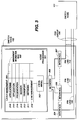
- FIG. 2 illustrates the software architecture of the switch nodes of FIG. 1. This architecture is based on the conventional OSI model modified to implement the ISDN protocol. Further modifications have been made to this model to incorporate the invention. Software layers 205 through 209 are described in U. S. Patent 5,386,466.
- the principal function of physical layer 201 is to terminate physical links. Specifically, physical layer 201 is responsive for maintaining physical channels and for controlling physical sub-channels thereon. Physical layer 201 comprises a software portion and physical interfaces. Further, the software portion of physical layer 201 is responsible for the direct control of the physical interface to which physical links communicate PRI and BRI information terminate. Physical layer 201 presents to link layer 212 physical sub-channels and physical channel as entities controllable by link layer 212. Since physical layer 201 is terminating the physical links, physical layer 201 determines when a D channel of the primary PRI link of a FAS group has failed because of the lost of framing on the channels of the D channel.
- link layer 212 The primary function of link layer 212 is to assure that the information transmitted over a physical channel is recovered intact and in the correct order. This is accomplished using another layer of protocol (referred to as the physical packet protocol) which allows multiple communications paths -- commonly referred to as logical links -- to be established on a given physical channel or a physical sub-channel communicating packetized data. These logical links are used to identify and process data being communicated between layer 212 and physical layer 201. In ISDN Q.921, the protocol used is the LAPD packet protocol. Further, link layer 212 allows higher software layers to control physical layer 201 in an abstract manner. Link layer 212 uses a first layer of software protocol.
- link layer 212 is divided into link interface 202 and link management 203. The reason for this division is set forth herein below. It will be helpful at this point to discuss the communication of ISDN signals over a D channel to help readers who have only a rudimentary knowledge of the communication of ISDN signals over a D channel.
- a plurality of logical links is established on a D channel. Only one of these logical links communicates ISDN control signals, and this logical link is referred to as a logical D channel (LDC).
- the LDC is identified by a logical D channel number (LDCN).
- Link interface 202 does the majority of the functions performed by link layer 212, including the establishment of logical links.
- Link management 203 identifies the various link interfaces for higher software layers. Further, link management 203 communicates information between the logical links and higher software layers.
- link management 403 is responsive to a signal from physical layer 201 indicating that the primary D channel has lost framing to switch to the D channel of the secondary PRI link of a FAS group.
- Network layer 204 processes information communicated on the LDCs and terminates the ISDN Q.931 protocol. Hence, this layer is responsible for negotiating the utilization of system resources for the termination or origination of calls external to a switching node.
- the network layer controls the allocation of channels on an interface on which a call is being received or set up.
- network layer 204 determines the primary and secondary D channels of a FAS group. For example, if switch node 102 receives a call from switch node 101 via PRI link 111, network layer 204 of switch node 102 negotiates with its peer layer (the corresponding network layer 204 in switch node 101) in order to obtain allocation of a D channel in PRI link 111.
- FIG. 3 illustrates, in block diagram form, the software architecture of FIG. 2 as implemented in switch node 102.
- Software layers 203 through 209 are implemented on the main processor of switch node 102 which is node processor 301.
- the software layers down through the link management portion of the link layer are realized by software layers denoted as 316 through 310 in node processor 301.
- the link interface portion of the link layer is implemented by a software module node in processor 301 designated as local angel 302.
- the physical layer is jointly implemented by hardware and software. Specifically, the hardware portion of the physical layer for switch node 102 is implemented by interfaces 304 through 307. The software portion of the physical layer is performed by local angel 302.
- PRI link 109 is the first PRI link between switch node 101 and switch node 102 to be initialized with PRI link 112 being the second.
- interface 304 and its corresponding interface in switch node 101 perform the necessary initial operations.
- One of these operations is the establishment of termination endpoint identifier (TEI) 412.
- TTI termination endpoint identifier
- Both the hardware and software operations upon a PRI link being initialized are set forth in detail in U. S. Patent 5,386,466.
- node numbers are exchanged between switch nodes 101 and 102, and switch node 102 determines that switch node 101 is higher in the hierarchy.
- connection endpoint suffix (CES) which is shown on FIG. 4 as CES 400.
- CES 400 and TEI 412 are logically connected to allow the communication of information.
- Link management 310 of FIG. 3 is responsive to the creation of CES 400 to create two logical links that terminate on virtual link object 431.
- Connection endpoint identifier 404 (also referred to as service access point identifier (SAPI) 0) is made operational on logical link 0 of D channel 421, and link management 310 establishes LAPD protocol 422 on this link and utilizing buffers 401.
- SAPI service access point identifier
- link management layer 310 establishes a communication link with its counterpart in switch node 101 on logical link 63 which is identified as CEI 403 (also referred to as SAPI 63) with the companion software entity LAPD 423 and buffers 402.
- network software layer 311 associate call records with LDCN 406 for any calls that are set up on PRI link 109.
- link management software layer 310 marks PRI link 109 as communicating the primary D channel for any FAS group that may be started.
- PRI link 112 is initialized between switch node 101 and switch node 102.
- the link interface software being executed in local angel 302 establishes logical links on D channel 420, establishes TEI 417, and identifies the TEI 417 to CES 410.
- link management software layer 310 establishes virtual link object 432 which comprises elements 408-411, 424 and 426.
- Link management 310 also marks in management information base 308 that PRI link 112 is the secondary PRI link.
- link management software layer 310 identifies PRI link 109 and PRI link 112 as comprising FAS group 104.
- link management software layer 310 does not identify CEI 411 as a SAPI 0 link to network software layer 311.
- network software layer 311 does not create an LDCN for this new SAPI 0 link.
- logical links 0 and 63 are set up on D channel 420, no messages are transmitted over these logical links while the primary PRI link 109 is properly functioning. Consequently, buffers 407 and 408 are empty.
- PRI link 111 and subsequent PRI links of FAS group 104 become active, no logical links are established on what would be the D channel of these new PRI links, but rather, that channel is used as another B channel. All calls that are set up on FAS group 104 are controlled by LDCN 406 as illustrated in FIG. 4.
- Link management 310 upon PRI link 109 becoming disabled.
- Interface 304 detects the loss of framing on D channel 421 as soon as PRI link 109 becomes disabled.
- Interface 304 reports this loss to link management software layer 310 via the link interface software.
- Link management 310 then directs the link interface software to communicate information between TEI 417 (which terminates D channel 420) and CES 400 rather than CES 410.
- the information in buffers 401 and 402 is still valid and has not been lost. Any packets which were in transit via PRI link 109 during the period of time that it became disabled will be recovered by the LAPD protocols 422 and 423 in conjunction with the LAPD protocols in switch node 101.
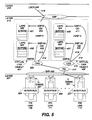
- Switch node 101 performs the same operations as performed by switch node 102. The result is illustrated in FIG. 5. Importantly, network software layer 311 never becomes aware of the change from D channel 421 to D channel 420; hence, network software layer 311 does not drop any calls. Note, that the higher software layers 312 through 316 are also totally unaware of the interchange of D channels.
- FIG. 6 illustrates the tables that comprise CEI 403, CEI 404, and CES 400 as shown on FIG. 4.
- the CES 611 and CES 601 entries in tables 608 and 618 respectively, define whether CES 400 or CES 410 of FIG. 4 is being utilized.
- channel number 622, interface number 623 and TEI 624 entries in table 628 define whether TEI 412 or TEI 417 of FIG. 4 is being utilized for communication of information.
- CES entries 601 and 611 are changed to reflect that TEI 417 is being utilized rather than TEI 412.
- the channel number entry defines the channel being utilized which in the case of a PRI link is channel 0.
- the interface number defines the physical interface, i.e., interface 304.
- the remainder of the entries are defined in U. S. Patent No. 4,386,466 which is hereby incorporated by reference.
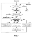
- FIG. 7 illustrates the operations of the link layer in setting up a FAS group and in processing the initialization of a new PRI link.
- Decision block 701 determines if a new link is initializing. If the answer is yes, block 702 establishes a TEI for this new PRI link. Decision block 703 then determines if there is already a PRI link going to the same destination switch node. If the answer is no, block 704 establishes the CES, and block 706 initializes the new link as a sole PRI link before transferring control back to decision block 701.
- decision block 707 determines if a FAS group has already been established. If the answer is yes in decision block 707, block 711 establishes the new PRI link using all of the channels as D channels before returning control back to 701. If the answer in decision block 707 is no, block 708 establishes the CES, and block 709 initializes the new link as a secondary link.
- FIG. 8 illustrates the operations performed by the link layer when a PRI link loses framing. If the answer in decision block 802 is no, block 803 processes the stimulus received by the link layer in the normal manner. If the answer in decision block 802 is yes, decision block 804 determines if the link is in a FAS group. If the answer is no in decision block 804, block 806 performs normal processing for a link that has lost framing. If the answer in decision block 804 is yes, decision block 807 determines if the primary link of the FAS group has lost framing.
- block 808 establishes communication between the TEI of the secondary link and the CES of the former primary link. This result is illustrated in FIG. 5.
- Block 809 marks the secondary link as the primary link in the management information base 308 of FIG. 3 before transferring control to decision block 813.
- decision block 813 determines whether it is possible to establish a new secondary link one of the other links presently in the FAS group. A new secondary link can only be established if channel 0 of one of the other links is idle so that this channel 0 can be designated as a D channel rather than a B channel. If the answer is no in decision block 813, block 814 performs normal processing. If the answer in decision block 813 is yes, block 816 establishes a new secondary link for the FAS group before transferring control back to decision block 701 of FIG. 7.
Landscapes
- Engineering & Computer Science (AREA)
- Computer Networks & Wireless Communication (AREA)
- Signal Processing (AREA)
- Data Exchanges In Wide-Area Networks (AREA)
- Telephonic Communication Services (AREA)
- Communication Control (AREA)
- Maintenance And Management Of Digital Transmission (AREA)
- Use Of Switch Circuits For Exchanges And Methods Of Control Of Multiplex Exchanges (AREA)
- Monitoring And Testing Of Exchanges (AREA)
Applications Claiming Priority (2)
| Application Number | Priority Date | Filing Date | Title |
|---|---|---|---|
| US08/672,887 US5831969A (en) | 1996-06-28 | 1996-06-28 | ISDN D channel restoration without loss of signaling or packet data |
| US672887 | 1996-06-28 |
Publications (3)
| Publication Number | Publication Date |
|---|---|
| EP0817527A2 true EP0817527A2 (fr) | 1998-01-07 |
| EP0817527A3 EP0817527A3 (fr) | 2001-01-03 |
| EP0817527B1 EP0817527B1 (fr) | 2007-08-22 |
Family
ID=24700431
Family Applications (1)
| Application Number | Title | Priority Date | Filing Date |
|---|---|---|---|
| EP97304221A Expired - Lifetime EP0817527B1 (fr) | 1996-06-28 | 1997-06-17 | Restauration du canal D du RNIS sans perte de données de signalisation ou en paquets |
Country Status (7)
| Country | Link |
|---|---|
| US (1) | US5831969A (fr) |
| EP (1) | EP0817527B1 (fr) |
| JP (1) | JPH1084593A (fr) |
| CN (1) | CN1103156C (fr) |
| AU (1) | AU2619597A (fr) |
| CA (1) | CA2202955C (fr) |
| DE (1) | DE69738041T2 (fr) |
Cited By (2)
| Publication number | Priority date | Publication date | Assignee | Title |
|---|---|---|---|---|
| WO2007118267A1 (fr) * | 2006-04-19 | 2007-10-25 | Uhs Systems Pty Ltd | Améliorations de liaisons de communication |
| EP2252005A4 (fr) * | 2008-04-11 | 2011-06-22 | Huawei Tech Co Ltd | Procédé de protection, dispositif et système de communication pour transmettre une signalisation |
Families Citing this family (12)
| Publication number | Priority date | Publication date | Assignee | Title |
|---|---|---|---|---|
| US6081841A (en) * | 1998-02-10 | 2000-06-27 | Ricoh Company, Ltd. | Method and apparatus for expanding data rate in an ISDN communication system |
| US6275578B1 (en) * | 1998-12-23 | 2001-08-14 | At&T Corp. | Method and apparatus for providing back-up, in-band signaling in a communications network |
| JP2000244562A (ja) * | 1999-02-18 | 2000-09-08 | Nec Corp | カットスルー伝送装置及びカットスルー伝送方法 |
| US6240107B1 (en) * | 1999-06-02 | 2001-05-29 | Adtran, Inc. | Self-configuring universal communication device for interfacing communication signals having different properties with repeaterless two-wire telephone link |
| FR2803711B1 (fr) * | 2000-01-06 | 2002-04-05 | Cit Alcatel | Procede de gestion de collision d'appels dans un canal de type canal d |
| US6738829B1 (en) * | 2000-10-16 | 2004-05-18 | Wind River Systems, Inc. | System and method for implementing a generic enhanced network driver |
| US6735296B2 (en) * | 2001-04-25 | 2004-05-11 | Lucent Technologies Inc. | Method and apparatus for swapping telephone numbers between switching modules |
| WO2006024225A1 (fr) * | 2004-08-29 | 2006-03-09 | Huawei Technologies Co., Ltd. | Procede de realisation d'une double inscription |
| CN101193093B (zh) * | 2007-01-30 | 2011-04-20 | 中兴通讯股份有限公司 | 双向串行通信断链的自动恢复方法和装置及使用系统 |
| US8761006B2 (en) * | 2009-10-13 | 2014-06-24 | At&T Intellectual Property I, L.P. | Method and apparatus for provisioning a backup signaling channel |
| CN109067509B (zh) * | 2018-08-22 | 2021-08-06 | 深圳市网心科技有限公司 | 分布式节点信令传输方法和系统、共享计算节点及信令网关 |
| CN117807383B (zh) * | 2024-03-01 | 2024-07-02 | 深圳市大数据研究院 | 信道状态信息恢复方法及装置、设备、存储介质 |
Family Cites Families (5)
| Publication number | Priority date | Publication date | Assignee | Title |
|---|---|---|---|---|
| DE3788577T2 (de) * | 1986-01-09 | 1994-07-07 | Nippon Electric Co | Paketvermitteltes Fernmeldenetz mit parallelen virtuellen Verbindungen zur Umweglenkung von Nachrichtenpaketen. |
| US5333187A (en) * | 1989-04-28 | 1994-07-26 | Hitachi, Ltd. | Switching system for electronic switcher |
| JPH0396054A (ja) * | 1989-09-08 | 1991-04-22 | Hitachi Ltd | Isdn網経由による共通線信号網構成方法および共通線信号路迂回方法 |
| JP2776977B2 (ja) * | 1990-11-07 | 1998-07-16 | 株式会社日立製作所 | Isdn通信システムの障害処理方法およびisdn通信システム |
| US5398236A (en) * | 1993-05-26 | 1995-03-14 | Nec America, Inc. | Asynchronous transfer mode link recovery mechanism |
-
1996
- 1996-06-28 US US08/672,887 patent/US5831969A/en not_active Expired - Lifetime
-
1997
- 1997-04-17 CA CA002202955A patent/CA2202955C/fr not_active Expired - Fee Related
- 1997-06-17 DE DE69738041T patent/DE69738041T2/de not_active Expired - Lifetime
- 1997-06-17 EP EP97304221A patent/EP0817527B1/fr not_active Expired - Lifetime
- 1997-06-23 AU AU26195/97A patent/AU2619597A/en not_active Abandoned
- 1997-06-26 CN CN97113999A patent/CN1103156C/zh not_active Expired - Fee Related
- 1997-06-27 JP JP9171305A patent/JPH1084593A/ja active Pending
Cited By (5)
| Publication number | Priority date | Publication date | Assignee | Title |
|---|---|---|---|---|
| WO2007118267A1 (fr) * | 2006-04-19 | 2007-10-25 | Uhs Systems Pty Ltd | Améliorations de liaisons de communication |
| EP2252005A4 (fr) * | 2008-04-11 | 2011-06-22 | Huawei Tech Co Ltd | Procédé de protection, dispositif et système de communication pour transmettre une signalisation |
| EP2509260A1 (fr) * | 2008-04-11 | 2012-10-10 | Huawei Technologies Co., Ltd. | Méthode, appareil et un système de communication pour la protection de la transmission de signalisation |
| RU2466505C2 (ru) * | 2008-04-11 | 2012-11-10 | Хуавэй Текнолоджиз Ко., Лтд. | Способ, устройство и система связи для защиты передачи сигнализации |
| US8593944B2 (en) | 2008-04-11 | 2013-11-26 | Huawei Technologies Co., Ltd. | Method, apparatus and communication system for protecting signaling transmission |
Also Published As
| Publication number | Publication date |
|---|---|
| JPH1084593A (ja) | 1998-03-31 |
| CA2202955A1 (fr) | 1997-12-28 |
| CN1171688A (zh) | 1998-01-28 |
| EP0817527A3 (fr) | 2001-01-03 |
| AU2619597A (en) | 1998-01-15 |
| CA2202955C (fr) | 2000-02-15 |
| CN1103156C (zh) | 2003-03-12 |
| US5831969A (en) | 1998-11-03 |
| DE69738041T2 (de) | 2008-05-15 |
| DE69738041D1 (de) | 2007-10-04 |
| EP0817527B1 (fr) | 2007-08-22 |
Similar Documents
| Publication | Publication Date | Title |
|---|---|---|
| US5848145A (en) | Automatic learning of network routing using random routes | |
| US5014266A (en) | Circuit switching system for interconnecting logical links between packet switching networks | |
| US5537404A (en) | Switched circuit connection management over public data networks for wide area networks | |
| US5831969A (en) | ISDN D channel restoration without loss of signaling or packet data | |
| EP0493912B1 (fr) | Commande à distance transparente d'un réseau de commutation | |
| EP0963662B1 (fr) | Procede visant a assurer l'activation d'une interface v5 | |
| US5991263A (en) | Channel and data link automatic restoration | |
| US5914939A (en) | Automatic learning of network routing by exchanging route information | |
| US5828652A (en) | Establishment of a flexible rate interface link to restore channels from a failed communication link | |
| EP0835038B1 (fr) | Restauration d'interface à débit de base RNIS sans perte d'appels | |
| EP0777397A2 (fr) | Augmentation de la capacité d'un système de communications personnel en utilisant le pontage de ligne partagée | |
| JP2731007B2 (ja) | 回線交換システム | |
| KR100333995B1 (ko) | 호출을손실함이없이isdnbri링크를복구하는방법및장치 | |
| JPH06177865A (ja) | 回線切替制御方法 | |
| KR100237473B1 (ko) | 협대역 종합정보통신망에서 패킷 영구 가상채널 설정방법 | |
| US20050071474A1 (en) | System for maintaining an active data link layer for ISDN call processing during a software reset operation | |
| JPH01248793A (ja) | 遠隔制御交換システムのチャネル割当て方法 | |
| JPH04346543A (ja) | 遠隔端末保守制御方式 | |
| JPH06276250A (ja) | 制御チャネル多重化方式 | |
| JPH03213043A (ja) | 信号方式 | |
| JPS61244159A (ja) | 通信中チヤネル変更方式 | |
| KR20020054193A (ko) | 액세스망의 브이 5.2 인터페이스에서 비씨씨 프로토콜을지원하기 위한 자원관리 제어방법 |
Legal Events
| Date | Code | Title | Description |
|---|---|---|---|
| PUAI | Public reference made under article 153(3) epc to a published international application that has entered the european phase |
Free format text: ORIGINAL CODE: 0009012 |
|
| AK | Designated contracting states |
Kind code of ref document: A2 Designated state(s): DE ES FR GB IT |
|
| PUAL | Search report despatched |
Free format text: ORIGINAL CODE: 0009013 |
|
| AK | Designated contracting states |
Kind code of ref document: A3 Designated state(s): AT BE CH DE DK ES FI FR GB GR IE IT LI LU MC NL PT SE |
|
| 17P | Request for examination filed |
Effective date: 20010703 |
|
| AKX | Designation fees paid |
Free format text: DE ES FR GB IT |
|
| GRAP | Despatch of communication of intention to grant a patent |
Free format text: ORIGINAL CODE: EPIDOSNIGR1 |
|
| GRAS | Grant fee paid |
Free format text: ORIGINAL CODE: EPIDOSNIGR3 |
|
| GRAA | (expected) grant |
Free format text: ORIGINAL CODE: 0009210 |
|
| AK | Designated contracting states |
Kind code of ref document: B1 Designated state(s): DE ES FR GB IT |
|
| REG | Reference to a national code |
Ref country code: GB Ref legal event code: FG4D |
|
| REF | Corresponds to: |
Ref document number: 69738041 Country of ref document: DE Date of ref document: 20071004 Kind code of ref document: P |
|
| ET | Fr: translation filed | ||
| PLBE | No opposition filed within time limit |
Free format text: ORIGINAL CODE: 0009261 |
|
| STAA | Information on the status of an ep patent application or granted ep patent |
Free format text: STATUS: NO OPPOSITION FILED WITHIN TIME LIMIT |
|
| 26N | No opposition filed |
Effective date: 20080526 |
|
| PG25 | Lapsed in a contracting state [announced via postgrant information from national office to epo] |
Ref country code: ES Free format text: THE PATENT HAS BEEN ANNULLED BY A DECISION OF A NATIONAL AUTHORITY Effective date: 20071203 |
|
| PGFP | Annual fee paid to national office [announced via postgrant information from national office to epo] |
Ref country code: IT Payment date: 20130620 Year of fee payment: 17 |
|
| PGFP | Annual fee paid to national office [announced via postgrant information from national office to epo] |
Ref country code: GB Payment date: 20140611 Year of fee payment: 18 |
|
| PGFP | Annual fee paid to national office [announced via postgrant information from national office to epo] |
Ref country code: DE Payment date: 20140611 Year of fee payment: 18 |
|
| PGFP | Annual fee paid to national office [announced via postgrant information from national office to epo] |
Ref country code: FR Payment date: 20140609 Year of fee payment: 18 |
|
| PG25 | Lapsed in a contracting state [announced via postgrant information from national office to epo] |
Ref country code: IT Free format text: LAPSE BECAUSE OF NON-PAYMENT OF DUE FEES Effective date: 20140617 |
|
| REG | Reference to a national code |
Ref country code: DE Ref legal event code: R119 Ref document number: 69738041 Country of ref document: DE |
|
| GBPC | Gb: european patent ceased through non-payment of renewal fee |
Effective date: 20150617 |
|
| REG | Reference to a national code |
Ref country code: FR Ref legal event code: ST Effective date: 20160229 |
|
| PG25 | Lapsed in a contracting state [announced via postgrant information from national office to epo] |
Ref country code: GB Free format text: LAPSE BECAUSE OF NON-PAYMENT OF DUE FEES Effective date: 20150617 Ref country code: DE Free format text: LAPSE BECAUSE OF NON-PAYMENT OF DUE FEES Effective date: 20160101 |
|
| PG25 | Lapsed in a contracting state [announced via postgrant information from national office to epo] |
Ref country code: FR Free format text: LAPSE BECAUSE OF NON-PAYMENT OF DUE FEES Effective date: 20150630 |