EP0820726A2 - Schliessvorrichtung für ein Aneurysma - Google Patents
Schliessvorrichtung für ein Aneurysma Download PDFInfo
- Publication number
- EP0820726A2 EP0820726A2 EP97305516A EP97305516A EP0820726A2 EP 0820726 A2 EP0820726 A2 EP 0820726A2 EP 97305516 A EP97305516 A EP 97305516A EP 97305516 A EP97305516 A EP 97305516A EP 0820726 A2 EP0820726 A2 EP 0820726A2
- Authority
- EP
- European Patent Office
- Prior art keywords
- occlusion
- retaining device
- lumen
- retaining
- delivery
- Prior art date
- Legal status (The legal status is an assumption and is not a legal conclusion. Google has not performed a legal analysis and makes no representation as to the accuracy of the status listed.)
- Granted
Links
- 206010002329 Aneurysm Diseases 0.000 title description 93
- 230000005012 migration Effects 0.000 claims abstract description 19
- 238000013508 migration Methods 0.000 claims abstract description 19
- 230000004888 barrier function Effects 0.000 claims abstract description 16
- 229910052751 metal Inorganic materials 0.000 claims abstract description 16
- 239000002184 metal Substances 0.000 claims abstract description 16
- 241000124008 Mammalia Species 0.000 claims abstract description 3
- RTAQQCXQSZGOHL-UHFFFAOYSA-N Titanium Chemical compound [Ti] RTAQQCXQSZGOHL-UHFFFAOYSA-N 0.000 claims abstract description 3
- 239000010936 titanium Substances 0.000 claims abstract description 3
- 238000004804 winding Methods 0.000 claims description 10
- 239000012530 fluid Substances 0.000 claims description 6
- PXHVJJICTQNCMI-UHFFFAOYSA-N Nickel Chemical compound [Ni] PXHVJJICTQNCMI-UHFFFAOYSA-N 0.000 claims description 4
- 239000007943 implant Substances 0.000 claims description 4
- 229910045601 alloy Inorganic materials 0.000 claims description 3
- 239000000956 alloy Substances 0.000 claims description 3
- 238000012544 monitoring process Methods 0.000 claims description 2
- 229910052759 nickel Inorganic materials 0.000 claims description 2
- 229910052719 titanium Inorganic materials 0.000 claims 1
- 229910001069 Ti alloy Inorganic materials 0.000 abstract description 2
- 229910000990 Ni alloy Inorganic materials 0.000 abstract 1
- 230000000903 blocking effect Effects 0.000 abstract 1
- 208000027418 Wounds and injury Diseases 0.000 description 24
- 238000000034 method Methods 0.000 description 18
- 238000013461 design Methods 0.000 description 15
- 230000007246 mechanism Effects 0.000 description 12
- 238000011282 treatment Methods 0.000 description 6
- 238000002513 implantation Methods 0.000 description 5
- 239000000463 material Substances 0.000 description 5
- 230000008901 benefit Effects 0.000 description 4
- 230000006870 function Effects 0.000 description 4
- 239000003795 chemical substances by application Substances 0.000 description 3
- 238000010276 construction Methods 0.000 description 3
- 208000014674 injury Diseases 0.000 description 3
- 238000003780 insertion Methods 0.000 description 3
- 230000037431 insertion Effects 0.000 description 3
- BASFCYQUMIYNBI-UHFFFAOYSA-N platinum Chemical compound [Pt] BASFCYQUMIYNBI-UHFFFAOYSA-N 0.000 description 3
- 230000008569 process Effects 0.000 description 3
- 230000004044 response Effects 0.000 description 3
- 230000002885 thrombogenetic effect Effects 0.000 description 3
- 230000008733 trauma Effects 0.000 description 3
- 206010003226 Arteriovenous fistula Diseases 0.000 description 2
- 208000036829 Device dislocation Diseases 0.000 description 2
- 238000004873 anchoring Methods 0.000 description 2
- 210000001367 artery Anatomy 0.000 description 2
- 230000000712 assembly Effects 0.000 description 2
- 238000000429 assembly Methods 0.000 description 2
- 230000017531 blood circulation Effects 0.000 description 2
- 238000007796 conventional method Methods 0.000 description 2
- 230000003628 erosive effect Effects 0.000 description 2
- 230000006872 improvement Effects 0.000 description 2
- 210000003739 neck Anatomy 0.000 description 2
- 229910001000 nickel titanium Inorganic materials 0.000 description 2
- 229910001285 shape-memory alloy Inorganic materials 0.000 description 2
- 239000000725 suspension Substances 0.000 description 2
- 230000002792 vascular Effects 0.000 description 2
- 210000005166 vasculature Anatomy 0.000 description 2
- 208000022211 Arteriovenous Malformations Diseases 0.000 description 1
- 208000005189 Embolism Diseases 0.000 description 1
- 206010028980 Neoplasm Diseases 0.000 description 1
- FAPWRFPIFSIZLT-UHFFFAOYSA-M Sodium chloride Chemical compound [Na+].[Cl-] FAPWRFPIFSIZLT-UHFFFAOYSA-M 0.000 description 1
- 208000007536 Thrombosis Diseases 0.000 description 1
- 229910052770 Uranium Inorganic materials 0.000 description 1
- HZEWFHLRYVTOIW-UHFFFAOYSA-N [Ti].[Ni] Chemical compound [Ti].[Ni] HZEWFHLRYVTOIW-UHFFFAOYSA-N 0.000 description 1
- 230000005856 abnormality Effects 0.000 description 1
- 230000004075 alteration Effects 0.000 description 1
- 230000006497 arterial abnormality Effects 0.000 description 1
- 230000005744 arteriovenous malformation Effects 0.000 description 1
- 230000015572 biosynthetic process Effects 0.000 description 1
- 210000004204 blood vessel Anatomy 0.000 description 1
- 238000005219 brazing Methods 0.000 description 1
- 230000036755 cellular response Effects 0.000 description 1
- 230000008859 change Effects 0.000 description 1
- 238000004891 communication Methods 0.000 description 1
- 239000002131 composite material Substances 0.000 description 1
- 239000004020 conductor Substances 0.000 description 1
- 230000008878 coupling Effects 0.000 description 1
- 238000010168 coupling process Methods 0.000 description 1
- 238000005859 coupling reaction Methods 0.000 description 1
- 238000004090 dissolution Methods 0.000 description 1
- 230000000694 effects Effects 0.000 description 1
- 238000005516 engineering process Methods 0.000 description 1
- 230000002708 enhancing effect Effects 0.000 description 1
- 239000000835 fiber Substances 0.000 description 1
- 239000000945 filler Substances 0.000 description 1
- 230000003890 fistula Effects 0.000 description 1
- PCHJSUWPFVWCPO-UHFFFAOYSA-N gold Chemical compound [Au] PCHJSUWPFVWCPO-UHFFFAOYSA-N 0.000 description 1
- 239000010931 gold Substances 0.000 description 1
- 229910052737 gold Inorganic materials 0.000 description 1
- 238000010438 heat treatment Methods 0.000 description 1
- 238000001727 in vivo Methods 0.000 description 1
- 230000003993 interaction Effects 0.000 description 1
- 230000001788 irregular Effects 0.000 description 1
- 239000007788 liquid Substances 0.000 description 1
- 230000014759 maintenance of location Effects 0.000 description 1
- 229910001092 metal group alloy Inorganic materials 0.000 description 1
- 239000002923 metal particle Substances 0.000 description 1
- 150000002739 metals Chemical class 0.000 description 1
- 230000004048 modification Effects 0.000 description 1
- 238000012986 modification Methods 0.000 description 1
- 210000003101 oviduct Anatomy 0.000 description 1
- 239000006223 plastic coating Substances 0.000 description 1
- 229910052697 platinum Inorganic materials 0.000 description 1
- -1 polytetrafluoroethylene Polymers 0.000 description 1
- 229920001343 polytetrafluoroethylene Polymers 0.000 description 1
- 239000004810 polytetrafluoroethylene Substances 0.000 description 1
- 230000000717 retained effect Effects 0.000 description 1
- 238000005476 soldering Methods 0.000 description 1
- 238000001356 surgical procedure Methods 0.000 description 1
- WFKWXMTUELFFGS-UHFFFAOYSA-N tungsten Chemical compound [W] WFKWXMTUELFFGS-UHFFFAOYSA-N 0.000 description 1
- 229910052721 tungsten Inorganic materials 0.000 description 1
- 239000010937 tungsten Substances 0.000 description 1
- 210000001177 vas deferen Anatomy 0.000 description 1
- 238000003466 welding Methods 0.000 description 1
Images


Classifications
-
- A—HUMAN NECESSITIES
- A61—MEDICAL OR VETERINARY SCIENCE; HYGIENE
- A61F—FILTERS IMPLANTABLE INTO BLOOD VESSELS; PROSTHESES; DEVICES PROVIDING PATENCY TO, OR PREVENTING COLLAPSING OF, TUBULAR STRUCTURES OF THE BODY, e.g. STENTS; ORTHOPAEDIC, NURSING OR CONTRACEPTIVE DEVICES; FOMENTATION; TREATMENT OR PROTECTION OF EYES OR EARS; BANDAGES, DRESSINGS OR ABSORBENT PADS; FIRST-AID KITS
- A61F2/00—Filters implantable into blood vessels; Prostheses, i.e. artificial substitutes or replacements for parts of the body; Appliances for connecting them with the body; Devices providing patency to, or preventing collapsing of, tubular structures of the body, e.g. stents
- A61F2/82—Devices providing patency to, or preventing collapsing of, tubular structures of the body, e.g. stents
- A61F2/86—Stents in a form characterised by the wire-like elements; Stents in the form characterised by a net-like or mesh-like structure
- A61F2/88—Stents in a form characterised by the wire-like elements; Stents in the form characterised by a net-like or mesh-like structure the wire-like elements formed as helical or spiral coils
-
- A—HUMAN NECESSITIES
- A61—MEDICAL OR VETERINARY SCIENCE; HYGIENE
- A61B—DIAGNOSIS; SURGERY; IDENTIFICATION
- A61B17/00—Surgical instruments, devices or methods
- A61B17/12—Surgical instruments, devices or methods for ligaturing or otherwise compressing tubular parts of the body, e.g. blood vessels or umbilical cord
- A61B17/12022—Occluding by internal devices, e.g. balloons or releasable wires
- A61B17/12099—Occluding by internal devices, e.g. balloons or releasable wires characterised by the location of the occluder
- A61B17/12109—Occluding by internal devices, e.g. balloons or releasable wires characterised by the location of the occluder in a blood vessel
- A61B17/12113—Occluding by internal devices, e.g. balloons or releasable wires characterised by the location of the occluder in a blood vessel within an aneurysm
- A61B17/12118—Occluding by internal devices, e.g. balloons or releasable wires characterised by the location of the occluder in a blood vessel within an aneurysm for positioning in conjunction with a stent
-
- A—HUMAN NECESSITIES
- A61—MEDICAL OR VETERINARY SCIENCE; HYGIENE
- A61B—DIAGNOSIS; SURGERY; IDENTIFICATION
- A61B17/00—Surgical instruments, devices or methods
- A61B17/12—Surgical instruments, devices or methods for ligaturing or otherwise compressing tubular parts of the body, e.g. blood vessels or umbilical cord
- A61B17/12022—Occluding by internal devices, e.g. balloons or releasable wires
- A61B17/12131—Occluding by internal devices, e.g. balloons or releasable wires characterised by the type of occluding device
- A61B17/1214—Coils or wires
- A61B17/12145—Coils or wires having a pre-set deployed three-dimensional shape
-
- A—HUMAN NECESSITIES
- A61—MEDICAL OR VETERINARY SCIENCE; HYGIENE
- A61B—DIAGNOSIS; SURGERY; IDENTIFICATION
- A61B17/00—Surgical instruments, devices or methods
- A61B17/12—Surgical instruments, devices or methods for ligaturing or otherwise compressing tubular parts of the body, e.g. blood vessels or umbilical cord
- A61B17/12022—Occluding by internal devices, e.g. balloons or releasable wires
- A61B17/12131—Occluding by internal devices, e.g. balloons or releasable wires characterised by the type of occluding device
- A61B17/1214—Coils or wires
- A61B17/12154—Coils or wires having stretch limiting means
-
- A—HUMAN NECESSITIES
- A61—MEDICAL OR VETERINARY SCIENCE; HYGIENE
- A61B—DIAGNOSIS; SURGERY; IDENTIFICATION
- A61B17/00—Surgical instruments, devices or methods
- A61B17/12—Surgical instruments, devices or methods for ligaturing or otherwise compressing tubular parts of the body, e.g. blood vessels or umbilical cord
- A61B17/12022—Occluding by internal devices, e.g. balloons or releasable wires
- A61B2017/1205—Introduction devices
- A61B2017/12054—Details concerning the detachment of the occluding device from the introduction device
- A61B2017/12063—Details concerning the detachment of the occluding device from the introduction device electrolytically detachable
-
- A—HUMAN NECESSITIES
- A61—MEDICAL OR VETERINARY SCIENCE; HYGIENE
- A61F—FILTERS IMPLANTABLE INTO BLOOD VESSELS; PROSTHESES; DEVICES PROVIDING PATENCY TO, OR PREVENTING COLLAPSING OF, TUBULAR STRUCTURES OF THE BODY, e.g. STENTS; ORTHOPAEDIC, NURSING OR CONTRACEPTIVE DEVICES; FOMENTATION; TREATMENT OR PROTECTION OF EYES OR EARS; BANDAGES, DRESSINGS OR ABSORBENT PADS; FIRST-AID KITS
- A61F2/00—Filters implantable into blood vessels; Prostheses, i.e. artificial substitutes or replacements for parts of the body; Appliances for connecting them with the body; Devices providing patency to, or preventing collapsing of, tubular structures of the body, e.g. stents
- A61F2/02—Prostheses implantable into the body
- A61F2/30—Joints
- A61F2002/30001—Additional features of subject-matter classified in A61F2/28, A61F2/30 and subgroups thereof
- A61F2002/30003—Material related properties of the prosthesis or of a coating on the prosthesis
- A61F2002/3006—Properties of materials and coating materials
- A61F2002/30092—Properties of materials and coating materials using shape memory or superelastic materials, e.g. nitinol
-
- A—HUMAN NECESSITIES
- A61—MEDICAL OR VETERINARY SCIENCE; HYGIENE
- A61F—FILTERS IMPLANTABLE INTO BLOOD VESSELS; PROSTHESES; DEVICES PROVIDING PATENCY TO, OR PREVENTING COLLAPSING OF, TUBULAR STRUCTURES OF THE BODY, e.g. STENTS; ORTHOPAEDIC, NURSING OR CONTRACEPTIVE DEVICES; FOMENTATION; TREATMENT OR PROTECTION OF EYES OR EARS; BANDAGES, DRESSINGS OR ABSORBENT PADS; FIRST-AID KITS
- A61F2210/00—Particular material properties of prostheses classified in groups A61F2/00 - A61F2/26 or A61F2/82 or A61F9/00 or A61F11/00 or subgroups thereof
- A61F2210/0014—Particular material properties of prostheses classified in groups A61F2/00 - A61F2/26 or A61F2/82 or A61F9/00 or A61F11/00 or subgroups thereof using shape memory or superelastic materials, e.g. nitinol
-
- A—HUMAN NECESSITIES
- A61—MEDICAL OR VETERINARY SCIENCE; HYGIENE
- A61F—FILTERS IMPLANTABLE INTO BLOOD VESSELS; PROSTHESES; DEVICES PROVIDING PATENCY TO, OR PREVENTING COLLAPSING OF, TUBULAR STRUCTURES OF THE BODY, e.g. STENTS; ORTHOPAEDIC, NURSING OR CONTRACEPTIVE DEVICES; FOMENTATION; TREATMENT OR PROTECTION OF EYES OR EARS; BANDAGES, DRESSINGS OR ABSORBENT PADS; FIRST-AID KITS
- A61F2250/00—Special features of prostheses classified in groups A61F2/00 - A61F2/26 or A61F2/82 or A61F9/00 or A61F11/00 or subgroups thereof
- A61F2250/0014—Special features of prostheses classified in groups A61F2/00 - A61F2/26 or A61F2/82 or A61F9/00 or A61F11/00 or subgroups thereof having different values of a given property or geometrical feature, e.g. mechanical property or material property, at different locations within the same prosthesis
- A61F2250/0039—Special features of prostheses classified in groups A61F2/00 - A61F2/26 or A61F2/82 or A61F9/00 or A61F11/00 or subgroups thereof having different values of a given property or geometrical feature, e.g. mechanical property or material property, at different locations within the same prosthesis differing in diameter
-
- A—HUMAN NECESSITIES
- A61—MEDICAL OR VETERINARY SCIENCE; HYGIENE
- A61F—FILTERS IMPLANTABLE INTO BLOOD VESSELS; PROSTHESES; DEVICES PROVIDING PATENCY TO, OR PREVENTING COLLAPSING OF, TUBULAR STRUCTURES OF THE BODY, e.g. STENTS; ORTHOPAEDIC, NURSING OR CONTRACEPTIVE DEVICES; FOMENTATION; TREATMENT OR PROTECTION OF EYES OR EARS; BANDAGES, DRESSINGS OR ABSORBENT PADS; FIRST-AID KITS
- A61F2310/00—Prostheses classified in A61F2/28 or A61F2/30 - A61F2/44 being constructed from or coated with a particular material
- A61F2310/00005—The prosthesis being constructed from a particular material
- A61F2310/00011—Metals or alloys
- A61F2310/00023—Titanium or titanium-based alloys, e.g. Ti-Ni alloys
Definitions
- This invention is an implantable medical device assembly for use in surgical procedures.
- the invention includes an artificial occlusion kit that uses a retaining device to prevent migration of artificial occlusion implants from an occlusion site, such as an aneurysm, and into an adjacent body space, such as a blood vessel.
- Implantable medical devices have been developed for treating various ailments associated with body lumens, such as ailments of body vessel walls or other lumenal walls.
- One category of implantable medical device that has been developed for artificial occlusion of body spaces is the category of "artificial occlusion devices.”
- artificial occlusion devices are useful in occluding body spaces, other applications include occluding body lumens.
- lumens that have been identified as candidates for treatment with artificial occlusion devices include, for example, the vas deferens or the fallopian tubes.
- artificial occlusion devices have been disclosed for medical treatment of the vascular lumens and aneurysms in the walls of such vessels. This treatment is commonly referred to as “artificial vaso-occlusion.”
- Artificial vaso-occlusion is a medical treatment that has involved techniques such as the delivery of various occlusive agents including solidifying suspensions, thrombogenic fluids, or emboli such as hog hair or suspensions of metal particles. Delivery of such agents or emboli normally causes a thrombogenic or other occlusive tissue response.
- occlusive agents including solidifying suspensions, thrombogenic fluids, or emboli such as hog hair or suspensions of metal particles. Delivery of such agents or emboli normally causes a thrombogenic or other occlusive tissue response.
- Recent advancements in artificial occlusion of vessels and aneurysms have included the delivery and implantation of metal coils. Implantable metal coils that are useful as artificial occlusion devices in vascular lumens or aneurysms are herein referred to as "vaso-occlusion coils.”
- Vaso-occlusion coils generally are constructed of a wire, usually made of a metal or metal alloy, that is wound into a helix.
- Vaso-occlusion coils are normally delivered through microcatheters such as the type disclosed in U.S. Patent No. 4,739,768 to Engelson.
- the microcatheter commonly tracks a guide wire to a point just proximal of or within the desired site for occlusion.
- the coil is advanced through the microcatheter and out the distal end hole so to at least partially fill the selected space and create an occlusion.
- vaso-occlusion results either from the space-filling mechanism inherent in the coil itself, or from a cellular response to the coil such as a thrombus formation, or both.
- the space-filling mechanism of the vaso-occlusion coil may be either based upon a pre-determined secondary geometry, or may be based upon random flow characteristics of the coil as it is expelled from a delivery sheath lumen.
- Vaso-occlusion coils have been disclosed that have a secondary geometry or shape which dictates at least in part their space-filling occlusion mechanism.
- a secondary shape may include a secondary helical structure which involves the primary coil helix being itself wound into a second helix.
- another benefit to having a secondary coil shape is that it may allow the coil readily to anchor itself against the walls of a delivery site.
- a vaso-occlusion coil having a secondary shape may be ejected from a sheath lumen where it was constrained in a stretched condition to have a first outer diameter equal to the sheath lumen inner diameter.
- the coil When ejected, the coil passively expands to its secondary shape, often having a larger, second outer diameter to aid in space-filling the body cavity or lumen. This may be an expansion to the coil's relaxed, unrestrained memory state--or at least until the coil encounters a vessel wall against which it exerts a force to complete the anchoring process.
- vaso-occlusion coil having a pre-determined secondary shape
- Ritchart describes a vaso-occlusive wire having a memory imparted thereto by heating the wire at about 800°F for 24 hours after it is shaped. This memory is effective to return the wire from a stretched, linear condition in which it is advanced through a catheter to a space-filling relaxed condition as the wire is released from the catheter.
- the diameter of the secondary shape is approximately equal to and may be larger than the vessel in which it is deployed.
- vaso-occlusion coils In contrast to vaso-occlusion coils having pre-determined secondary shapes that dictate in part their space-filling mechanism, other vaso-occlusion coils have been disclosed that take on random shapes when expelled from a delivery sheath. This type of vaso-occlusive coil is often referred to as the "liquid coil.”
- This type of vaso-occlusive coil is often referred to as the "liquid coil.”
- One example of such a vaso-occlusive coil which takes on a random occlusive shape when delivered into a body space is disclosed in pending U.S. Patent Application Serial No. 08/413,970, filed March 30, 1995. This document describes very soft and flexible coils which are flow-injectable through the delivery catheter using, e.g., saline solution.
- vaso-occlusion coils In addition to the various types of space-filling mechanisms and geometries of vaso-occlusion coils, other particularized features of coil designs, such as mechanisms for delivering vaso-occlusion coils through delivery catheters and implanting them in a desired occlusion site, have also been described. Examples of categories of vaso-occlusion coils based upon their delivery mechanisms include pushable coils, mechanically detachable coils, and electrolytically detachable coils.
- Pushable coils are commonly provided in a cartridge and are pushed or “plunged” from the cartridge into a delivery catheter lumen. A pusher rod advances the pushable coil through and out of the delivery catheter lumen and into the site for occlusion.
- mechanically detachable vaso-occlusion coils are integrated with a pusher rod and mechanically detached from the pusher after exiting a delivery catheter. Examples of such mechanically detachable vaso-occlusion coils are provided in U.S. Patent No. 5,261,916 to Engelson, or U.S. Patent No. 5,250,071 to Palermo.
- the electrolytically detachable type is also integrated with a pusher rod, but is detached from the pusher by applying a direct current that dissolves a sacrificial link between the pusher and the coil.
- Examples of such electrolytically detachable vaso-occlusion coils are disclosed in U.S. Patent No. 5,122,136 to Guglielmi. et al, and U.S. Patent No. 5,354,295 to Guglielmi, et al.
- vaso-occlusion coils having vaso-occlusive fibers attached thereto have been described (see for example, U.S. Patent. No. 5,226,911 to Chee et al.).
- a further type of vaso-occlusion coil is used as a detachable dielectric electrode in a radio-frequency artificial vaso-occlusion system, as disclosed in pending U.S. Patent Appl. Ser. No. 08/497,507, filed June 30, 1995.
- a wide variety of clinical abnormalities in body lumens may be treated with artificial occlusion methods.
- artificial occlusion methods have been disclosed for treating feeder vessels into tumors, arterio-venous malformations, fistulas, and aneurysms of vessel walls.
- aneurysms present particular medical risk due to the dangers of potential rupture of the thinned wall inherent in an aneurysm. Occlusion of aneurysms with vaso-occlusion coils without occluding the adjacent artery is a desirable method of reducing such risk.
- a microcatheter is initially steered into or adjacent the entrance of an aneurysm. aided by a steerable wire. The wire is then withdrawn from the microcatheter lumen and replaced by the vaso-occlusion coil.
- the vaso-occlusion coil is advanced through and out of the microcatheter, desirably being completely delivered into the aneurysm. After or during delivery of such a coil into the aneurysm, a portion of the coil might then migrate out of the aneurysm entrance zone and into the feeding vessel. This may cause an undesirable response of occluding the feeding vessel. Also, there is an additional risk that the blood flow may induce movement of the coil farther out of the aneurysm, resulting in a more developed embolus in the good vessel.
- Aneurysm commonly referred to as a "wide-neck aneurysm,” is known to present particular difficulty in placing and retaining vaso-occlusion coils.
- Wide-neck aneurysms are herein referred to as aneurysms of vessel walls having a neck or "entrance zone" from the adjacent vessel, which entrance zone has a diameter that either: (1) is at least 80% of the largest diameter of the aneurysm; or (2) is clinically observed to be too wide to effectively retain vaso-occlusion coils that are deployed using conventional techniques.
- catheter distal tip shapes may be formed on delivery microcatheters to help support the distal tip during deployment of vaso-occlusive agents.
- this may provide only a partial solution, particularly in the case of wide-neck aneurysms.
- a retaining device that is adapted to block an entrance zone to an aneurysm such that occlusion devices may be implanted in and retained within the aneurysm and are prevented from migrating through the entrance zone of the aneurysm and into the adjacent vessel.
- This invention is a novel artificial occlusion kit, which includes a novel implantable medical device useful for retaining occlusion devices at an occlusion site, and related method for use.
- a particularly useful application of the invention is in the treatment of wide-neck aneurysms and aneurysms emanating from a curving vessel..
- An artificial occlusion kit for implanting and retaining an artificial occlusion device in a body space adjacent to and extending from a body lumen in a mammal.
- the artificial occlusion kit has at least one occlusion device adapted for filling at least a portion of the body space, and a retaining device assembly that includes a retaining device.
- the retaining device of the artificial occlusion kit is adapted to be delivered and implanted at a retaining site in the body lumen adjacent to the body space to be occluded.
- This retaining device has a first shape that is radially expandable to a diameter that is sufficient to engage the wall of the body lumen at a retaining site adjacent the body space to be occluded.
- the retaining device When engaged with the body lumen wall, the retaining device forms a lumen having a diameter that is sufficient to allow flow therethrough, and also forms a barrier that prevents occlusion devices that are implanted in the body space from migrating out of the body space and into the adjacent body lumen.
- the first shape is formed when the retaining device is radially constrained during delivery to the retaining site, and a second shape with an expanded outer diameter is formed when the retaining device is released from radial constraint at the retaining site.
- Either a coaxial delivery sheath or a coaxial delivery wire may provide this radial constraint.
- the retaining device may be balloon expandable from the first shape to the second shape.
- At least one semi-penetrable space is provided in the barrier formed at the entrance zone into the body space to be occluded.
- This retaining device may be delivered to the retaining site, followed by introduction of at least one occlusion device into the body space to be occluded through the semi-penetrable space.
- the retaining device may be a metal wire wound into a primary helix that has a secondary geometry which is also a secondary helix.
- the adjacent windings of the secondary helix may be the semi-penetrable space provided by the appropriate retaining device variation.
- the semi-penetrable space is sized to allow at least one occlusion device, when radially artificially constrained to a first occlusion device outer diameter, to be inserted therethrough. Subsequent release of the radial constraint on the occlusion device allows it to reconfigure to a second outer diameter which prevents migration back through the semi-penetrable space.
- the semi-penetrable space of the retaining device is distendable.
- a delivery catheter with a tapered tip may be provided such that the semi-penetrable space is distendable by forcing the delivery catheter tip therethrough and into the body space to be occluded.
- an introducer wire is provided to distend the semi-penetrable spaces of the retaining device. At least one occlusion device is introduced into the body space to be occluded either coaxially through the delivery catheter or over the introducer wire.
- the retaining device is a wire wound into a primary helix over a core member.
- the core member is a metal, preferably a shape-memory alloy, and most preferably a shape-memory alloy of nickel and titanium.
- the wire is also preferably a metal, most preferably radiopaque.
- Each of the variations discussed herein may further include a smaller diameter "leading helix" in the retaining device to assist in the alignment and deployment of the retaining device as it exits the catheter.
- An implantable medical device assembly having the structure described for the retaining device of the novel artificial occlusion kit and which is attached to an elongate pusher via a sacrificial link that is electrolytically dissolvable.
- this implantable medical device may take the form of the "wire wound over core member" variation described for the artificial vaso-occlusion kit aspect of the invention.
- This invention includes methods for using the apparatus here described.
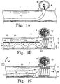
- Figure 1A shows a side view of a vessel with an aneurysm in its wall, wherein a vaso-occlusion coil component of an artificial occlusion kit is shown being delivered into the aneurysm.
- Figure 1B shows a side view of the vessel and aneurysm of Figure 1A, wherein a retaining device assembly of the artificial occlusion kit is shown being delivered to a retaining site in the vessel adjacent the aneurysm which is substantially filled with a plurality of vaso-occlusion coils.
- Figure 1C shows a side view of the same vessel and aneurysm wherein the retaining device is shown electrolytically detached from a pusher, the retaining device engaging the vessel wall adjacent the entrance zone of the aneurysm, bridging across the entrance zone to form a barrier against vaso-occlusion coil migration into the vessel, and forming a lumen allowing for physiological flow through the vessel.
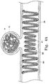
- Figures 2A-2C show in partial section, a side view of an electrolytically deployed device.
- Figure 3 shows in side view cross-section, a portion of the device shown in figures 2A-2C emphasizing the section of the device employing an electrolytically erodible link.
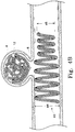
- Figures 4A, 4B, and 4C show in partial cut-away, cross-section, variations of the shape of retainers made according to this invention.
- Figure 5 shows a side view of a vessel having in its wall a wide-neck aneurysm, showing a variation of the artificial occlusion kit where the retaining device has a semi-penetrable space through which an artificial occlusion device is being introduced into an aneurysm.
- Figure 6 shows a side view of a vessel having in its wall a wide-neck aneurysm, showing a variation of the artificial occlusion kit where the retaining device has a distensible semi-penetrable space that is shown distended by a delivery catheter through which vaso-occlusion coils are being introduced into the aneurysm.
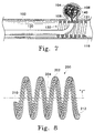
- Figure 7 shows a side view of the vessel and wide-neck aneurysm, showing a further variation of the assembly shown in Figure 5, wherein the distensible semi-penetrable space is shown distended by an introducer wire over which vaso-occlusion coils are being coaxially advanced into the aneurysm.
- Figure 8 shows a perspective view of a further variation of retaining device wherein the retaining device is shown to be constructed of a wire wound into a helix over a core member, the helical wire and core member being formed into a secondary geometry.
- Figures 9A and 9B show in schematic cross-section anatomically shaped filler coils suitable for use in conjunction with the retention devices made according to this invention.
- the present invention provides a novel solution to the problem of vaso-occlusion device migration out of aneurysms or other implantation sites and into the feeding vessels that are not the target of vaso-occlusion.
- a retaining device is used in a novel artificial occlusion assembly to prevent migration of one or more occlusion devices from a target occlusion site by forming a barrier at the entrance zone to the target site from a feeding vessel.
- Variations of a novel implantable medical device are provided as the retaining device, which novel implantable medical device is included within the scope of the present invention.
- Figures 1A-C show sequential steps of a novel method of occluding a body space -- here an aneurysm of a body lumen wall -- using one artificial occlusion kit embodiment of the current invention.
- a retaining device is provided in a kit together with at least one vaso-occlusion device, which kit is also shown in use with at least one delivery catheter.
- Figure 1A shows the first of a plurality of vaso-occlusion coils is shown as it is being implanted into an aneurysm.
- a retaining device of a retaining device assembly is shown being delivered to a retaining site in the body lumen adjacent the aneurysm after the aneurysm is substantially occluded with vaso-occlusion coils.
- the retaining device is completely implanted at the retaining site and detached from a pusher via electrolytic detachment from a pusher.
- the implanted retaining device shown forms a barrier against migration of the vaso-occlusion coils from the aneurysm and into the body lumen, while maintaining an open conduit for flow through the body lumen.
- FIG. 1A a cut-away side view of a vessel (2) having an aneurysm (4) in its wall is shown.
- Vaso-occlusion coil (8) is shown being delivered into aneurysm (4) out of the distal end of delivery catheter (10) in order to occlude the aneurysm (4).
- Vaso-occlusion coil (8) for the purposes ofthis invention may be any one of a wide variety of coils that are known in the art for occluding vessels or aneurysms.
- vaso-occlusion coil (8) may be a pushable coil of the type described in US 4,994,069.
- coil (8) may be a mechanically detachable coil such as that described in US 5,261,916 or US 5,250,071.
- coil (8) may be an electrolytically detachable coil such as that described in US 5,122,136 or US 5,354,294.
- vaso-occlusion coil (8) may have a pre-formed secondary shape that is constrained in a stretched orientation when being delivered through delivery catheter (10) but reconfigures when delivered beyond delivery catheter (10). Such reconfiguring often includes radial expansion to a relaxed memory state having a desired, pre-determined shaped geometry.
- coil (8) may have highly flexible portions that ball up from random convolutions formed while the coil flows distally during delivery, such as the coils described in pending US Pat. Appl. No. 08/413,970, filed March 30, 1995.
- vaso-occlusion coil The type and geometry of vaso-occlusion coil are normally chosen for the particular delivery mechanism and space-filling characteristics, as may be appropriate for a particular occlusion site.
- the disclosures of the above referenced vaso-occlusion coil documents are herein incorporated by reference.
- the appropriate design for delivery catheter (10) is defined by the ability to reach the desired occlusion site atraumatically and to efficaciously deliver the vaso-occlusion coil into the site as an occlusion implant.
- a catheter that may be used in the present invention is described in US 4,739,768 to Engelson, the disclosure of which is herein incorporated by reference.
- FIG. 1B shows a retaining device (19) being delivered through delivery catheter (20) and into vessel (2) at the site of aneurysm (4).
- a plurality of vaso-occlusion coils (12) is also shown having been implanted into aneurysm (4) prior to delivery of the retaining device (19).
- Retaining device (19) is shown as a distal segment of a retaining device assembly (15), wherein it is attached at its proximal end to a pusher (16) which is relatively more stiff than the implantable retaining device (19).
- Pusher (16) is adapted for advancing the retaining device percutaneously through the delivery catheter (20), even when in tortuous bends of the vasculature, into remote internal body spaces for occlusion.
- retaining device (19) and pusher (16) are shown to be coupled or attached via a joint or link (17).
- retaining device (19) and pusher (16) can be either electrolytically detachable at link (17) or mechanically detachable at link (17).
- link (17) is electrolytically dissolvable when current is applied thereto.
- Electrolytic detachment mechanisms of the types described in US 5,122,136 or US 5,354,295 may be suitable.
- pusher (16) and retaining device (19) are mechanically detachably engaged at link (17).
- the mechanical detachment mechanisms of the types described in US 5,261,916 or US 5,250,071 may be suitable.
- a retaining device to prevent migration of vaso-occlusion devices from an occlusion site need not be limited to use with a "detachable" pusher-retaining device mechanism as is shown in retaining device assembly (15). It may be equally efficacious, and perhaps even preferred in a given circumstance, to use separate, non-attached retaining device and pusher without the need for a detachable link such as link (17).
- pushers such as the type described in US 4,994,069 to Ritchart et al. may be satisfactory.
- the distal end of the pusher can be advanced axially within a delivery catheter lumen to abut a proximal end of the retaining device, also disposed within the delivery lumen. With the distal pusher end in confronting engagement with the retaining device proximal end, further advancement of the pusher by the user will effectively push the retaining device distally through the lumen, out of the delivery catheter from a distal port thereof, and into a vessel site adjacent a body space where occlusion devices are deployed.
- retaining device (19) has a memory in the form of a pre-determined, shaped, secondary geometry.
- Retaining device (19) is shown to have a first shape with a first outer diameter "A" where it is positioned within delivery catheter (20).
- retaining device (19) When released from a radially constraining condition, retaining device (19) also forms a second shape with a second outer diameter greater than the first outer diameter "A.” and sufficient to engage the vessel wall.
- retaining device (19) is shown extending beyond the distal delivery port of the delivery lumen (22) where it is radially artificially unconstrained and expanded to an outer diameter "B" larger than the first diameter "A,” engaging the lumen wall at the retaining site adjacent the aneurysm.
- the completely relaxed, unconstrained second outer diameter of the retaining device may be slightly greater than the diameter of the vessel. This may be necessary in order to maintain accurate placement of the retaining device in the vessel lumen at the aneurysm site.
- the purpose of the retaining device is merely to form a barrier at the entrance zone of the aneurysm to prevent occlusion coil migration. Unnecessary trauma to the vessel wall, such as from oversizing or coil designs that are too stiff to perform the stated purpose should be avoided.
- Retaining device (19) is shown in Figure 1B to have a helical geometry.
- retaining device (19) is a metal wire that is wound into a primary helix, shown in Figure 1B having a primary helix diameter "C".
- This primary helix is preferably pre-formed into a secondary geometry that, as shown for this embodiment, is also in the form of a secondary helix. Therefore.
- the first and second shapes and corresponding first and second outer diameters that the retaining device takes when being delivered to and implanted in the vessel, respectively, are defined by the secondary geometry of the retaining device. These shapes are formed about a longitudinal axis, shown in Figure 1B at "L,” and their respective outer diameters are defined on a radial plane perpendicular to that axis.
- Retaining device (19) is also shown in Figure 1B to form a lumen (30).
- lumen (30) is defined by the simple helical shape of the retaining device's secondary geometry and extends along the longitudinal axis "L" of that helix. It is contemplated that first and second shapes other than a simple helix may still fall within the scope of the present invention.
- the purpose of the retaining device is to form a barrier at the entrance zone to the body space being artificially occluded by occlusion devices. Occlusion of the body lumen adjacent to the occlusion site is to be avoided in the use of the present invention. It is therefore an important aspect of the present invention that there be a physiologically acceptable through-lumen formed by the retaining device when implanted into the body lumen.
- delivery catheter (10) may be the same catheter as that used for delivering the occlusion devices, such as delivery catheter (10) in Figure 1A.
- the two delivery catheters may in certain circumstances have different required characteristics for delivering the occlusion devices and retaining devices, respectively.
- a desired tip shape for delivering the occlusion devices into an aneurysm radially at the vessel wall may be different than the tip shape appropriate for delivering the retaining device transversely into the vessel lumen adjacent the aneurysm.
- the retaining device and the occluding devices are characteristically of different designs, since one's function is to substantially space fill and the other's is to form a barrier at the aneurysm and also to keep the vessel lumen open.
- the delivery catheters for the two designs may require different delivery lumen diameters, material construction. etc. as may be appropriate according to one of ordinary skill.
- a delivery wire may provide a coaxial rail over which a retaining device may be advanced such as by a pusher located proximally of the retaining device.
- the retaining device may have a lumen that coaxially tracks the delivery wire, the delivery wire providing radial constraint on the retaining device to form the first radially constrained shape. Advancing the retaining device distally past the end of the delivery wire releases the radial constraint and allows the retaining device to expand to a second shape.
- a further retaining device variation may be delivered upon and expanded by a balloon on the distal end of a balloon catheter.
- the retaining device is provided for delivery to the retaining site while it is formed in its first shape coaxially engaged over a balloon in a deflated state.
- inflation of the balloon radially expands the retaining device into a second shape having an outer diameter sufficient to engage the vessel wall and which forms a barrier across the entrance zone to an aneurysm.
- Subsequent deflation and withdrawal of the balloon leaves the radially expanded retaining device implanted at the retaining site, which retaining device forms a lumen where the expanded balloon once was.
- FIG. 1C a particular retaining device variation is shown detached at the retaining site in vessel (2) that is adjacent to a body space to be occluded, here aneurysm (4).
- Retaining device (19) is shown having a shape that is expanded along its length to a diameter sufficient to engage the vessel wall at regions adjacent an entrance zone (6) to aneurysm (4).
- Retaining device (19) also bridges across entrance zone (6) and forms a barrier against any of the plurality of vaso-occlusion devices (12) from migrating out of the aneurysm and into vessel (2).
- retaining device (19) has been detached from pusher (16) by means of electrolytic or erosive severing of link (17).
- electrolytic detachment may occur via the systems and methods as described in US 5,122,136; US 5,354,294; or co-pending US Pat. Appl. No. 08/499,525, filed on July 7, 1995, as may be apparent to one of ordinary skill in the art. The disclosures of these documents have previously been incorporated by reference.
- the retaining device of the current invention is not an occlusion device and must provide a through-lumen for flow when implanted into a vessel lumen (in fact the opposite function of the previously disclosed electrolytically detachable occlusion devices).
- Electrode (40) may be a skin electrode having a relatively high surface area in contact with the patient when compared to that of link (17).
- retaining device assembly (15) is disposed within the body such that link (17) is in patient contact. Since electrode (40) is in skin contact with the patient, a circuit may be formed wherein direct current from power source “E” may pass through link (17), quickly dissipate at a low current density through the patient as an electrical conductor, and through electrode (40) back to power source “E.” This current serves to dissolve link (17) until retaining device (19) is detached from pusher (16).
- Power source "E” may additionally superimpose an alternating current over the direct current signal, which alternating current signal may be sensed by a sensing circuit (not shown) as an indicator of the progression of electrolytic detachment at link (17). Additionally, a control circuit (not shown) may be used to alter the output power signal or shut the signal off upon the sensing of a critical parameter by the sensing circuit, such as the sensing of a particular change in the alternating current component of the output signal.
- a critical parameter such as the sensing of a particular change in the alternating current component of the output signal.
- the electrolytic detachment allows for minimal engaging structure at the detachable coupling end of the implantable medical device (as compared to mechanically detachable designs which may require clasps, enlarged balls, etc. on the end of the implant coil). It is believed, therefore, that electrolytic dissolution of link (17) thus provides an optimal solution for implanting an implantable medical device for use as an occlusion coil retaining device.
- FIGS 2A-2C depict a different variation of the artificial occlusion kit.
- a vaso-occlusive coil (12) is maintained in an aneurysm (4) emanating from an artery (2) by a retaining device assembly (30) which is delivered to the site of the aneurysm (4) by guidewire.
- the retaining device assembly (30) is maintained in a radially compressed fashion by the use of a pair of electrolytic links (32, 33).
- a pair of electrolytic links 32, 33
- Figure 2A shows the retaining device assembly (30) closely coiled to the body of the core or guidewire (31).
- the retaining device assembly (30) is of a material or has been treated in such a way that the "normal" or relaxed condition of the retaining device assembly (30) is as shown in Figure 2C.
- a single wire device is depicted in Figures 2A, 2B and 2C, but a helically wound coil is certainly suitable as well.
- the retaining device assembly (30) must be either insulated in its entirety from the surrounding fluid (via, e.g., a plastic coating or the like) or of a material which is more noble or higher in the electromotive series than are the links (32) and (33) shown in the drawing.
- this detachment link operates via the electrolytic erosion of the bare links found at (32) and (33).
- the link found at (33) is smaller in diameter than is the link found at (32).
- link (33) erodes to a point where it breaks earlier than does the link at (32) simply because of the smaller diameter of link (33).
- link (33) has disintegrated as is shown in Figure 2B, link (32) continues to electrolytically erode as time passes.
- the second joint (32) has broken and the retaining device assembly (30) has expanded as shown in Figure 2C, the core wire and its allied parts (31) are removed.
- Figure 3 shows a portion of the core wire (31) with the retaining device assembly (30) closely disposed on its outer surface as would be the case in Figure 2A.
- the inner core (36) is covered by an insulating layer (37) of, e.g., a polytetrafluoroethylene.
- the displayed link (33) is in an electrical contact with the core (36) and holds the retaining device assembly (30) in close contact with the core wire assembly (31). It is this link (33) which erodes to release the retaining device assembly (30).
- Figure 4A shows a variation of the overall shape of a retaining device assembly (38) made in keeping with this invention.
- the retaining device assembly (38) has two end regions (39) which have a diameter when deployed which approximates (or is slightly larger than) the inner diameter of the vessel lumen into which it is placed.
- the retaining device assembly (38) has a center section (41) which has a smaller overall radius than the two end sections (39).
- the smaller mid-section (41) has a variety of benefits. For instance, it does not press on the vessel or on the coil (12) within aneurysm (4). Yet it is sufficiently close to the mouth of aneurysm (4) to prevent coil (12) from migrating to other parts of the body.
- the retaining device assembly (38) made in this form is easier to move should it be mal-placed in the human body. It has smaller regions in contact with the vessel lumen.
- the shape of the device is not particularly critical in many of these variations.
- the shape of retaining device assembly (38) must be sufficiently appropriate for it to maintain the coil (12) within aneurysm (14). It must have sufficient radial springiness to allow its shape to be maintained in the lumen of the body vessel described herein.
- the retaining devices shown in the Figures will not achieve the desirable generally cylindrical shape found in those Figures. This problem can be alleviated in a variety of ways. A careful user will find it possible to twist the catheter during the initial ejection of a couple of turns of the retaining device assembly to maintain the device in the proper orientation in the lumen. Some users will find that the use of a catheter distal tip having a turn will help in deployment f the retainer.
- One very effective and highly desirable method of preventing the retainer from turning in the vessel lumen during deployment is found in Figures 4B and 4C.
- the retaining device assembly (43 in Figure 4B and 46 in Figure 4C), incorporates a leading or distal helix section which has a deployed diameter which is smaller than the diameter of the vessel lumen.
- the retaining device assembly (43) is first deployed to the right (or distal end) of the Figure.
- the proximal end of the retaining device assembly has a diameter (44) which is equal to or larger than the diameter of the vessel lumen.
- the earlier deployed distal end has a smaller diameter (45).
- the smaller diameter distal section exits the catheter end and simply forms a tubular cylinder within the lumen of the vessel.
- the distal end of the retainer device assembly (43) conceptually forms an indexing end and aligns the remainder of the retainer device assembly (43) with the lumen for further deployment.
- the distal diameter (45) should not be appreciably smaller than the lumen diameter (44) lest the retaining device assembly (43) begin to block blood flow. We believe that the distal diameter (45) should be at least 75% of the lumen diameter (44).
- proximal diameter portion of the retaining device assembly (43) does not completely cover the mouth (6) ofthe aneurysm (4) in the Figures. This is not critical but the is an option in this variation.
- Figure 4C shows a similar variation of the invention in which the distal portion of the retaining device assembly (46) is stepped and has two short sections of respectively smaller diameters (48,49).
- a further artificial occlusion kit embodiment allows for implantation of the retaining device prior to implantation of occlusion devices, an embodiment particularly useful in "wide-neck" aneurysms.
- occlusion devices may not be implantable at all into the aneurysm without immediate migration into a flowing vessel prior to insertion of a retaining device at the entrance zone.
- This embodiment solves this problem by providing semi-penetrable spaces in the retaining device at the entrance zone from the body lumen to the adjacent body space to be occluded.
- the retaining device in the variations of this embodiment may be a helically wound member, wherein the semi-penetrable space for occlusion device insertion is provided by the space between adjacent windings of the helix.
- the helically wound member that forms the retaining device is a metal wire wound into a primary helix which is further wound into a secondary helix. In this mode, windings of the secondary helix form the semi-penetrable space for occlusion device insertion.
- the pre-determined, semi-penetrable space (60) of retaining device (69) is defined by the space between adjacent helical windings (58) and (59).
- This semi-penetrable space (60) is equal to or greater in diameter than occlusion device (62) when it is being introduced into aneurysm (54).
- semi-penetrable space (60) is less than the diameter of occlusion device (62) after it is in the aneurysm.
- the spacing provided by the retaining device allows the introduction of occlusion devices into the aneurysm but does not allow significant migration of occlusion devices. once implanted, back into the adjacent vessel lumen (53).
- the occlusion device (62) is radially constrained to a first shape having a first outer diameter when within the delivery lumen of delivery catheter (70).
- the delivery catheter distal end is abutting the inner surface of the retaining device (69).
- the occlusion device (62) is then advanced out the distal end of the delivery catheter (70) and through the space in the retaining device (69), where it is then radially artificially unconstrained.
- the occlusion device (62) takes on a second shape having a second outer diameter that prevents it from migrating back through the semi-penetrable space and into the body lumen (53).
- the semi-penetrable spaces of the retaining device are distensible. This distensibility enhances the semi-penetrability of the spaces. More specifically, occlusion devices may be introduced through such spaces when an applied force distends open the spaces. Once the occlusion devices are implanted into the occlusion site, however, passive migration of the devices back through the spaces does not provide the requisite force to distend open these spaces--the passive migration is thus prevented.
- a particular occlusion device may be used in conjunction with a retaining device, and be of such construction and dimension that it may be advanced unaided through the spaces provided in the retaining device.
- detachable occlusion devices such as those described in US 5,122,136 or US 5,354,295 may be constructed with sufficient pushability to be advanced between adjacent coil winds of the retaining device and into the aneurysm sac. They may thereafter be detached within the aneurysm for occlusion.
- FIG. 6 Another aspect of this variation is shown in Figure 6.
- retaining device (119) is shown implanted into vessel (102) such that it radially engages the vessel wall adjacent to entrance zone (106) to wide-neck aneurysm (104) and bridges across entrance zone (106).
- the helical shape of retaining device (119) is shown to have a pre-determined spacing which may be spread when adjacent helical windings are forced apart.
- delivery catheter (110) is advanced through the retaining device and into the entrance zone (106) of the aneurysm (104).
- delivery catheter (110) has a tip (111) which is tapered and dimensioned such that adjacent helical windings of retaining device (119) are forced apart when delivery catheter (110) is forced radially against the retaining device (119) from its inner lumen (130) and toward the entrance zone (106).
- delivery catheter (110) may, for example, have a pre-shaped bend in the distal delivery catheter region ending in tip (111). This shape may aid in the advancement of the delivery catheter through the branching vasculature, or may also be sufficiently straightened coaxially over a guidewire to avoid proximal vessel trauma while tracking to the site.
- an introducer wire (140) may be forced through spaces provided in the retaining device, such as between adjacent winds of a helically shaped retaining device as shown in Figure 7.
- a delivery catheter such as delivery catheter (110) (shown in Figure 6) may thereafter be advanced coaxially over the introducer wire (140) and into the entrance zone of the wide-neck aneurysm.
- delivery catheter (120) is not shown to be advanced into entrance zone (106) or aneurysm (104), but rather is advanced merely to abut the inner diameter of the helical windings forming retaining device (119).
- Vaso-occlusion coil (108) is shown being advanced coaxially over introducer wire (140) while advancing through delivery catheter (120), through adjacent windings of helical retaining device (119), and ultimately off the distal end of introducer wire (140) and into the sac of aneurysm (104).
- vaso-occlusion coil (108) may occur, for example, by coaxially advancing a pusher member, located proximally of vaso-occlusion coil (108), in the distal direction against a proximal end of vaso-occlusion coil.
- introducer wire (140) may also be shapeable such that it is adapted for tracking to the retaining site adjacent the aneurysm, as well as for advancing through the spaces in the retaining device barrier at the aneurysm entrance zone.
- Conventional guidewires of the type known in the art may perform sufficiently as introducer wire (140) in a particular case.
- the present invention further contemplates obvious alterations to known wire designs in order to function with the individual features of a particular retaining device design, as may be apparent to one of ordinary skill.
- Such particularized retaining device features that may dictate introducer wire design parameters, for example, may be the diameter and degree of distensibility of the semi-permeable space.
- the implantable medical device that functions as a retaining device in the novel artificial occlusion kit has a particular construction that includes a wire (202) wound into a primary helix over an inner core member (204).
- the inner core member (204) and primary wire helix are also wound into a secondary geometry, and are soldered or welded at both of two ends (210) and (212).
- the secured ends (210) and (212) serve to secure the "wire over core” composite relationship and also provide smooth ends for safety considerations in this implantable device.
- the inner core member (204) is a metal mandrel, and more preferably is a superelastic alloy of nickel-titanium.
- the inner core member (204) is constructed of a nickel-titanium alloy and has an outer diameter from 0.003" to 0.006".
- the helically wound wire (202) in this preferred variation may be a radiopaque metal, such as platinum, gold, or tungsten, and has an outer diameter in the range of 0.001" to 0.006".
- the coil may have 0-100% spacing.
- wire (202) is wound at a pitch of 0.001" to 0.008" with 0-100% spacing. For instance, a coil made with 0.003" wire with 0.006" pitch has 100% spacing; a coil with 0.003" wire and 0.006" pitch has 0 % spacing.
- wire (202) is secured to the inner core member (204) using the following process: the coil is secured to the inner core member at least two or several locations, preferably at both ends.
- One method for joining the components involves resistance welding or a similar such process. Soldering or brazing is similarly useful in joining the metals.
- the inner core member (204) is chosen such as to provide the requisite shape memory and stiffness.
- This inner core member may not by itself provide optimal radiopacity, since it is not chosen for that purpose.
- the requisite radiopacity of the device may instead be provided by the outer wound coil (202), which might not provide optimal stiffness or material memory if it were only available alone in the device. It is believed that the combined features of this "wire over core” design may optimally adapt prior known implantable coil technologies to meet the particular structural needs of a retaining device in the current invention.
- the elongate retaining device be flexible along its length so that it can be implanted into lumens having bends.
- too much flexibility may correspond to irregular and random conformations of the coil when implanted in-vivo, which may produce an occlusive effect.
- a primary helical coil wound into a secondary helix without more. may be too flexible to effectively engage a vessel wall along the requisite length to form a barrier against occlusion device migration.
- the addition of the mandrel in what would otherwise be the primary helix lumen provides a stiffening structure that still allows for a certain controlled flexibility of the secondary helical shape.
- prior vaso-occlusion coils require substantial space filling for effective cross-sectional blockage of a body lumen, for example.
- only a minimal portion of the device may be required to actually radially engage a vessel wall for primarily the purpose of anchoring the device at the occlusion site.
- This means only a small portion of the coil may need to reconfigure from a first constrained diameter during delivery to a second diameter at least approximating the lumenal wall diameter when delivered. It may be acceptable, even desirable, for such occlusion coils to have portions not so significantly altered in their cross-sectional diameter when they are delivered at an implantation site, so long as their shape presents an occlusion to flow.
- the present inventive retaining device must take on a shape at the retaining site that has sufficient outer diameter along a sufficient length of the device to form an effective barrier across the aneurysm entrance zone at the vessel wall. Impinging into the lumen's cross-section is generally undesirable.
- the reconfiguration to this expanded shape from a first radially constrained shape during delivery may correspond to a higher degree of requisite material memory than is possible from a simple fine wire wound into the primary and secondary helix shapes as previously disclosed.
- An inner core mandrel may offer the structure necessary to provide such memory.
- the wire forming the primary helical core is wound much tighter than a similar wire might be wound to optimally form an occlusion device. It is believed that coil stiffness may be controlled by adjusting the outer diameter of the primary coil helix (e.g. tightness of winding) to which a given wire is wound. It is believed that, by providing one preferred retaining device may comprise a wire wound very tightly, into a primary helix that has also a secondary shape.
- One preferred application of this "tightly wound" variation comprises a platinum wire of 0.005" outer diameter wound over a .009" mandrel.
- common known occlusion coils for occluding aneurysms is constructed a .005" wire wound over a .011" mandrel.
- a wire having an outer diameter of .003" may be wound over a mandrel having an outer diameter of 0.007".
- the wire is thereafter annealed in the wound shape to form a primary coil of pre-determined dimensions.
- a secondary shape may then be imparted to the primary coil, which secondary shape may also be a helical coil.
- the ultimate goal of the particular artificial occlusion kits, novel components thereof, and related methods described above is to occlude aneurysms having entrance zones or necks that are of such width and geometry that conventional techniques would result in unwanted migration of occlusion devices from the aneurysm and into the adjacent vessel.
- the assemblies, components, and methods of the present invention that were conceived of in order to meet this need may provide additional benefits in other medical treatments.
- the invention contemplates retaining device designs that meet the general requirements of the novel artificial occlusion kit but vary from the specific variations just described.
- the artificial occlusion kit embodiments and variations have been described specifically as applied to aneurysms in vessel walls.
- other occlusion sites adjacent to and in fluid communication with body lumens may present similar concerns as to migration of occlusion devices from an occlusion site and into an adjacent lumen.
- a vessel that branches off of a feeding vessel may be a body space to be occluded and the feeding vessel at a region adjacent to the branching vessel may be a desired retaining site.
- the present invention contemplates use of the apparatus embodiments described in such body spaces and lumens in addition to aneurysm sites in vessels.
- the invention also broadly contemplates a retaining device structure that is expandable at a retaining site of a body lumen to form a barrier against migration of at least one occlusion device through an entrance zone between an occlusion site and an adjacent lumen, and that also provides a lumen for flow through the body lumen at the retaining site.
- a retaining device structure that is expandable at a retaining site of a body lumen to form a barrier against migration of at least one occlusion device through an entrance zone between an occlusion site and an adjacent lumen, and that also provides a lumen for flow through the body lumen at the retaining site.
- Examples have been provided in the form of shape memory coils delivered through radially confining delivery sheaths or over delivery wires, in addition to an alternative balloon expandable retaining device embodiment.
- Various specific retaining device designs that meet the broad requirements provided, beyond the particular variations provided, are within the scope of this invention.
- At least one novel electrolytically detachable implantable medical device has been conceived of for use as a retaining device in the artificial occlusion kit.
- This novel implantable medical device may have useful medical applications in addition to retaining artificial occlusion devices.
- the scope of this aspect of the invention, while intimately pertaining to an artificial occlusion kit, should not be limited to the kit embodiments described for artificial occlusion.
Landscapes
- Health & Medical Sciences (AREA)
- Life Sciences & Earth Sciences (AREA)
- Surgery (AREA)
- Engineering & Computer Science (AREA)
- Biomedical Technology (AREA)
- Animal Behavior & Ethology (AREA)
- Veterinary Medicine (AREA)
- Vascular Medicine (AREA)
- Public Health (AREA)
- Heart & Thoracic Surgery (AREA)
- General Health & Medical Sciences (AREA)
- Molecular Biology (AREA)
- Medical Informatics (AREA)
- Nuclear Medicine, Radiotherapy & Molecular Imaging (AREA)
- Reproductive Health (AREA)
- Cardiology (AREA)
- Oral & Maxillofacial Surgery (AREA)
- Transplantation (AREA)
- Neurosurgery (AREA)
- Surgical Instruments (AREA)
- Prostheses (AREA)
- Media Introduction/Drainage Providing Device (AREA)
- Materials For Medical Uses (AREA)
Applications Claiming Priority (2)
| Application Number | Priority Date | Filing Date | Title |
|---|---|---|---|
| US08/690,183 US5980514A (en) | 1996-07-26 | 1996-07-26 | Aneurysm closure device assembly |
| US690183 | 1996-07-26 |
Publications (3)
| Publication Number | Publication Date |
|---|---|
| EP0820726A2 true EP0820726A2 (de) | 1998-01-28 |
| EP0820726A3 EP0820726A3 (de) | 1998-04-15 |
| EP0820726B1 EP0820726B1 (de) | 2003-09-10 |
Family
ID=24771444
Family Applications (1)
| Application Number | Title | Priority Date | Filing Date |
|---|---|---|---|
| EP97305516A Expired - Lifetime EP0820726B1 (de) | 1996-07-26 | 1997-07-23 | Schliessvorrichtung für ein Aneurysma |
Country Status (11)
| Country | Link |
|---|---|
| US (3) | US5980514A (de) |
| EP (1) | EP0820726B1 (de) |
| JP (2) | JP3205526B2 (de) |
| KR (1) | KR980008179A (de) |
| AT (1) | ATE249171T1 (de) |
| AU (1) | AU709076B2 (de) |
| CA (1) | CA2211512C (de) |
| DE (1) | DE69724712T2 (de) |
| ES (1) | ES2202553T3 (de) |
| NO (1) | NO973373L (de) |
| TW (1) | TW359601B (de) |
Cited By (40)
| Publication number | Priority date | Publication date | Assignee | Title |
|---|---|---|---|---|
| WO1999030640A1 (en) * | 1997-12-15 | 1999-06-24 | Boston Scientific Limited | Sheet metal aneurysm neck bridge |
| WO1999056636A1 (en) * | 1998-05-04 | 1999-11-11 | Micrus Corporation | Method and apparatus for occlusion and reinforcement of aneurysms |
| WO1999066846A1 (en) * | 1998-06-24 | 1999-12-29 | Boston Scientific Limited | Detachable, varying flexibility, aneurysm neck bridge |
| EP0947180A3 (de) * | 1998-03-31 | 2000-01-05 | Cordis Corporation | Stent Aneurismus-Behandlungssystem und Einführverfahren |
| WO2000007524A1 (en) * | 1998-08-05 | 2000-02-17 | Advanced Cardiovascular Systems, Inc. | Intra-luminal device for treatment of body cavities and lumens and method of use |
| WO1999063896A3 (en) * | 1998-06-12 | 2000-02-17 | Scimed Life Systems Inc | Aneurysm closure device assembly |
| WO2000013593A1 (en) * | 1998-09-04 | 2000-03-16 | Boston Scientific Limited (Incorporated In Ireland) | Detachable aneurysm neck closure patch |
| WO2000021443A1 (en) * | 1998-10-09 | 2000-04-20 | Cook Incorporated | Vasoocclusion coil device having a core therein |
| US6168592B1 (en) | 1996-07-26 | 2001-01-02 | Target Therapeutics, Inc. | Aneurysm closure device assembly |
| WO2001003607A3 (en) * | 1999-07-12 | 2001-07-26 | Scimed Life Systems Inc | Aneurysm closure device assembly |
| WO2000004845A3 (en) * | 1998-07-24 | 2001-10-25 | Micrus Corp | Intravascular flow modifier and reinforcement device |
| WO2002013706A3 (en) * | 2000-08-11 | 2002-05-16 | Scimed Life Systems Inc | Variable softness vaso-occlusive coils |
| WO2001093780A3 (en) * | 2000-06-08 | 2002-06-20 | Micrus Corp | Intravascular flow modifier and reinforcement device |
| US6632241B1 (en) | 2000-03-22 | 2003-10-14 | Endovascular Technologies, Inc. | Self-expanding, pseudo-braided intravascular device |
| US6638293B1 (en) | 1996-02-02 | 2003-10-28 | Transvascular, Inc. | Methods and apparatus for blocking flow through blood vessels |
| EP1475042A2 (de) | 1998-06-16 | 2004-11-10 | Boston Scientific Limited | Intravaskulärer Stent zum Uberbrücken eines Aneurysmas |
| WO2005009253A1 (en) * | 2003-07-24 | 2005-02-03 | Scimed Life Systems, Inc. | Improved embolic coil |
| US6872218B2 (en) | 1998-12-15 | 2005-03-29 | Micrus Corporation | Variable stiffness coil for vasoocclusive devices |
| US6951571B1 (en) | 2004-09-30 | 2005-10-04 | Rohit Srivastava | Valve implanting device |
| EP1001707B1 (de) * | 1997-08-05 | 2006-03-08 | Boston Scientific Limited | Vaso-okklusive anordnung |
| WO2006060453A1 (en) * | 2004-12-01 | 2006-06-08 | Boston Scientific Limited | Embolic coils |
| US7316701B2 (en) | 1995-04-20 | 2008-01-08 | Micrus Endovascular Corporation | Three dimensional, low friction vasoocclusive coil, and method of manufacture |
| US7326225B2 (en) | 1997-12-05 | 2008-02-05 | Micrus Endovascular Corporation | Vasoocclusive device for treatment of aneurysms |
| US7410482B2 (en) | 1998-09-04 | 2008-08-12 | Boston Scientific-Scimed, Inc. | Detachable aneurysm neck bridge |
| US8388650B2 (en) | 2008-09-05 | 2013-03-05 | Pulsar Vascular, Inc. | Systems and methods for supporting or occluding a physiological opening or cavity |
| US8535345B2 (en) | 2004-10-07 | 2013-09-17 | DePuy Synthes Products, LLC | Vasoocclusive coil with biplex windings to improve mechanical properties |
| US8545530B2 (en) | 2005-10-19 | 2013-10-01 | Pulsar Vascular, Inc. | Implantable aneurysm closure systems and methods |
| US8551132B2 (en) | 2005-10-19 | 2013-10-08 | Pulsar Vascular, Inc. | Methods and systems for endovascularly clipping and repairing lumen and tissue defects |
| US8790363B2 (en) | 1995-04-20 | 2014-07-29 | DePuy Synthes Products, LLC | Three dimensional, low friction vasoocclusive coil, and method of manufacture |
| US8870908B2 (en) | 2007-08-17 | 2014-10-28 | DePuy Synthes Products, LLC | Twisted primary coil for vascular therapy |
| US9119625B2 (en) | 2011-10-05 | 2015-09-01 | Pulsar Vascular, Inc. | Devices, systems and methods for enclosing an anatomical opening |
| US9259229B2 (en) | 2012-05-10 | 2016-02-16 | Pulsar Vascular, Inc. | Systems and methods for enclosing an anatomical opening, including coil-tipped aneurysm devices |
| US9277924B2 (en) | 2009-09-04 | 2016-03-08 | Pulsar Vascular, Inc. | Systems and methods for enclosing an anatomical opening |
| US9687245B2 (en) | 2012-03-23 | 2017-06-27 | Covidien Lp | Occlusive devices and methods of use |
| US9713475B2 (en) | 2014-04-18 | 2017-07-25 | Covidien Lp | Embolic medical devices |
| US10004510B2 (en) | 2011-06-03 | 2018-06-26 | Pulsar Vascular, Inc. | Systems and methods for enclosing an anatomical opening, including shock absorbing aneurysm devices |
| US10335155B2 (en) | 2011-11-30 | 2019-07-02 | Covidien Lp | Positioning and detaching implants |
| US10624647B2 (en) | 2011-06-03 | 2020-04-21 | Pulsar Vascular, Inc. | Aneurysm devices with additional anchoring mechanisms and associated systems and methods |
| US10893868B2 (en) | 2012-01-20 | 2021-01-19 | Covidien Lp | Aneurysm treatment coils |
| US11684371B2 (en) | 2013-03-15 | 2023-06-27 | Embo Medical Limited | Embolization systems |
Families Citing this family (337)
| Publication number | Priority date | Publication date | Assignee | Title |
|---|---|---|---|---|
| USRE42625E1 (en) | 1990-03-13 | 2011-08-16 | The Regents Of The University Of California | Endovascular electrolytically detachable wire and tip for the formation of thrombus in arteries, veins, aneurysms, vascular malformations and arteriovenous fistulas |
| US6083220A (en) | 1990-03-13 | 2000-07-04 | The Regents Of The University Of California | Endovascular electrolytically detachable wire and tip for the formation of thrombus in arteries, veins, aneurysms, vascular malformations and arteriovenous fistulas |
| USRE42756E1 (en) | 1990-03-13 | 2011-09-27 | The Regents Of The University Of California | Endovascular electrolytically detachable wire and tip for the formation of thrombus in arteries, veins, aneurysms, vascular malformations and arteriovenous fistulas |
| US6190402B1 (en) | 1996-06-21 | 2001-02-20 | Musc Foundation For Research Development | Insitu formable and self-forming intravascular flow modifier (IFM) and IFM assembly for deployment of same |
| US5733329A (en) * | 1996-12-30 | 1998-03-31 | Target Therapeutics, Inc. | Vaso-occlusive coil with conical end |
| US5980554A (en) * | 1997-05-05 | 1999-11-09 | Micro Therapeutics, Inc. | Wire frame partial flow obstruction for aneurysm treatment |
| WO1999008607A1 (en) * | 1997-08-05 | 1999-02-25 | Boston Scientific Limited | Detachable aneurysm neck bridge |
| US6168570B1 (en) | 1997-12-05 | 2001-01-02 | Micrus Corporation | Micro-strand cable with enhanced radiopacity |
| DK173411B2 (da) * | 1998-06-19 | 2007-04-16 | Coloplast As | Opsamlingspose til menneskelige legemssekreter |
| US6248112B1 (en) | 1998-09-30 | 2001-06-19 | C. R. Bard, Inc. | Implant delivery system |
| US6458092B1 (en) | 1998-09-30 | 2002-10-01 | C. R. Bard, Inc. | Vascular inducing implants |
| US6432126B1 (en) | 1998-09-30 | 2002-08-13 | C.R. Bard, Inc. | Flexible vascular inducing implants |
| US6254612B1 (en) * | 1998-10-22 | 2001-07-03 | Cordis Neurovascular, Inc. | Hydraulic stent deployment system |
| US6692520B1 (en) | 1998-12-15 | 2004-02-17 | C. R. Bard, Inc. | Systems and methods for imbedded intramuscular implants |
| US6203779B1 (en) * | 1999-03-19 | 2001-03-20 | Charlie Ricci | Methods for treating endoleaks during endovascular repair of abdominal aortic aneurysms |
| US6620170B1 (en) | 1999-04-26 | 2003-09-16 | C. R. Bard, Inc. | Devices and methods for treating ischemia by creating a fibrin plug |
| WO2000069345A1 (en) * | 1999-05-14 | 2000-11-23 | C.R. Bard, Inc. | Implant anchor systems |
| US6986784B1 (en) | 1999-05-14 | 2006-01-17 | C. R. Bard, Inc. | Implant anchor systems |
| US20020169473A1 (en) * | 1999-06-02 | 2002-11-14 | Concentric Medical, Inc. | Devices and methods for treating vascular malformations |
| US6719805B1 (en) | 1999-06-09 | 2004-04-13 | C. R. Bard, Inc. | Devices and methods for treating tissue |
| US6277082B1 (en) | 1999-07-22 | 2001-08-21 | C. R. Bard, Inc. | Ischemia detection system |
| US6855160B1 (en) | 1999-08-04 | 2005-02-15 | C. R. Bard, Inc. | Implant and agent delivery device |
| US6709667B1 (en) * | 1999-08-23 | 2004-03-23 | Conceptus, Inc. | Deployment actuation system for intrafallopian contraception |
| US6419675B1 (en) * | 1999-09-03 | 2002-07-16 | Conmed Corporation | Electrosurgical coagulating and cutting instrument |
| US6602261B2 (en) | 1999-10-04 | 2003-08-05 | Microvention, Inc. | Filamentous embolic device with expansile elements |
| US6238403B1 (en) * | 1999-10-04 | 2001-05-29 | Microvention, Inc. | Filamentous embolic device with expansible elements |
| US6790218B2 (en) * | 1999-12-23 | 2004-09-14 | Swaminathan Jayaraman | Occlusive coil manufacture and delivery |
| US20050187564A1 (en) * | 1999-12-23 | 2005-08-25 | Swaminathan Jayaraman | Occlusive coil manufacturing and delivery |
| US7232421B1 (en) | 2000-05-12 | 2007-06-19 | C. R. Bard, Inc. | Agent delivery systems |
| US7153323B1 (en) * | 2000-06-30 | 2006-12-26 | Boston Scientific Scimed, Inc. | Aneurysm liner with multi-segment extender |
| US7204847B1 (en) | 2000-07-28 | 2007-04-17 | C. R. Bard, Inc. | Implant anchor systems |
| US6554849B1 (en) * | 2000-09-11 | 2003-04-29 | Cordis Corporation | Intravascular embolization device |
| IL155015A0 (en) | 2000-09-21 | 2003-10-31 | Atritech Inc | Apparatus for implanting devices in atrial appendages |
| US7029486B2 (en) * | 2000-09-26 | 2006-04-18 | Microvention, Inc. | Microcoil vaso-occlusive device with multi-axis secondary configuration |
| US6605101B1 (en) * | 2000-09-26 | 2003-08-12 | Microvention, Inc. | Microcoil vaso-occlusive device with multi-axis secondary configuration |
| US6589265B1 (en) | 2000-10-31 | 2003-07-08 | Endovascular Technologies, Inc. | Intrasaccular embolic device |
| US6569194B1 (en) | 2000-12-28 | 2003-05-27 | Advanced Cardiovascular Systems, Inc. | Thermoelastic and superelastic Ni-Ti-W alloy |
| US7294137B2 (en) * | 2001-03-27 | 2007-11-13 | Boston Scientific Scimed | Device for multi-modal treatment of vascular lesions |
| DE10118017B4 (de) * | 2001-04-10 | 2017-04-13 | Dendron Gmbh | Occlusionswendel und Vorrichtung zur Implantation von Occlusionswendeln |
| US6616676B2 (en) * | 2001-04-10 | 2003-09-09 | Scimed Life Systems, Inc. | Devices and methods for removing occlusions in vessels |
| CA2689598A1 (en) * | 2001-05-29 | 2002-12-05 | Microvention, Inc. | Method of manufacturing expansile filamentous embolization devices |
| US6673106B2 (en) * | 2001-06-14 | 2004-01-06 | Cordis Neurovascular, Inc. | Intravascular stent device |
| US6623506B2 (en) * | 2001-06-18 | 2003-09-23 | Rex Medical, L.P | Vein filter |
| WO2002102280A2 (en) | 2001-06-18 | 2002-12-27 | Rex Medical, L.P. | Removable vein filter |
| US6783538B2 (en) | 2001-06-18 | 2004-08-31 | Rex Medical, L.P | Removable vein filter |
| US6793665B2 (en) * | 2001-06-18 | 2004-09-21 | Rex Medical, L.P. | Multiple access vein filter |
| US8282668B2 (en) * | 2001-06-18 | 2012-10-09 | Rex Medical, L.P. | Vein filter |
| US7179275B2 (en) * | 2001-06-18 | 2007-02-20 | Rex Medical, L.P. | Vein filter |
| US20030100945A1 (en) | 2001-11-23 | 2003-05-29 | Mindguard Ltd. | Implantable intraluminal device and method of using same in treating aneurysms |
| US20030014075A1 (en) * | 2001-07-16 | 2003-01-16 | Microvention, Inc. | Methods, materials and apparatus for deterring or preventing endoleaks following endovascular graft implanation |
| US7011671B2 (en) | 2001-07-18 | 2006-03-14 | Atritech, Inc. | Cardiac implant device tether system and method |
| US8252040B2 (en) | 2001-07-20 | 2012-08-28 | Microvention, Inc. | Aneurysm treatment device and method of use |
| US8715312B2 (en) * | 2001-07-20 | 2014-05-06 | Microvention, Inc. | Aneurysm treatment device and method of use |
| US7572288B2 (en) * | 2001-07-20 | 2009-08-11 | Microvention, Inc. | Aneurysm treatment device and method of use |
| GB0121980D0 (en) | 2001-09-11 | 2001-10-31 | Cathnet Science Holding As | Expandable stent |
| US6811560B2 (en) * | 2001-09-20 | 2004-11-02 | Cordis Neurovascular, Inc. | Stent aneurysm embolization method and device |
| US6802851B2 (en) * | 2001-09-20 | 2004-10-12 | Gordia Neurovascular, Inc. | Stent aneurysm embolization method using collapsible member and embolic coils |
| EP1300120A1 (de) * | 2001-10-08 | 2003-04-09 | Jomed Nv | Stentanbringungssystem |
| DE10155191A1 (de) * | 2001-11-12 | 2003-05-22 | Dendron Gmbh | Medizinisches Implantat |
| US20060292206A1 (en) | 2001-11-26 | 2006-12-28 | Kim Steven W | Devices and methods for treatment of vascular aneurysms |
| US7147656B2 (en) | 2001-12-03 | 2006-12-12 | Xtent, Inc. | Apparatus and methods for delivery of braided prostheses |
| US20030135266A1 (en) | 2001-12-03 | 2003-07-17 | Xtent, Inc. | Apparatus and methods for delivery of multiple distributed stents |
| US20040186551A1 (en) | 2003-01-17 | 2004-09-23 | Xtent, Inc. | Multiple independent nested stent structures and methods for their preparation and deployment |
| US7294146B2 (en) | 2001-12-03 | 2007-11-13 | Xtent, Inc. | Apparatus and methods for delivery of variable length stents |
| US7270668B2 (en) * | 2001-12-03 | 2007-09-18 | Xtent, Inc. | Apparatus and methods for delivering coiled prostheses |
| US7182779B2 (en) | 2001-12-03 | 2007-02-27 | Xtent, Inc. | Apparatus and methods for positioning prostheses for deployment from a catheter |
| US7892273B2 (en) | 2001-12-03 | 2011-02-22 | Xtent, Inc. | Custom length stent apparatus |
| US7351255B2 (en) | 2001-12-03 | 2008-04-01 | Xtent, Inc. | Stent delivery apparatus and method |
| US7309350B2 (en) | 2001-12-03 | 2007-12-18 | Xtent, Inc. | Apparatus and methods for deployment of vascular prostheses |
| US8080048B2 (en) | 2001-12-03 | 2011-12-20 | Xtent, Inc. | Stent delivery for bifurcated vessels |
| US7137993B2 (en) | 2001-12-03 | 2006-11-21 | Xtent, Inc. | Apparatus and methods for delivery of multiple distributed stents |
| CN1638703A (zh) | 2002-01-25 | 2005-07-13 | 阿特里泰克公司 | 心房附件血液过滤系统 |
| US8062251B2 (en) * | 2002-02-01 | 2011-11-22 | Vascular Designs, Inc. | Multi-function catheter and use thereof |
| US20050267407A1 (en) * | 2002-02-01 | 2005-12-01 | Vascular Designs, Inc. | Multi-function catheter and use thereof |
| CA2476263C (en) * | 2002-02-01 | 2012-08-21 | Robert J. Goldman | Multi-function catheter and use thereof |
| US6989024B2 (en) | 2002-02-28 | 2006-01-24 | Counter Clockwise, Inc. | Guidewire loaded stent for delivery through a catheter |
| US7695488B2 (en) * | 2002-03-27 | 2010-04-13 | Boston Scientific Scimed, Inc. | Expandable body cavity liner device |
| US7195648B2 (en) * | 2002-05-16 | 2007-03-27 | Cordis Neurovascular, Inc. | Intravascular stent device |
| DE10233085B4 (de) * | 2002-07-19 | 2014-02-20 | Dendron Gmbh | Stent mit Führungsdraht |
| US8425549B2 (en) | 2002-07-23 | 2013-04-23 | Reverse Medical Corporation | Systems and methods for removing obstructive matter from body lumens and treating vascular defects |
| EP1526815A1 (de) | 2002-07-31 | 2005-05-04 | MicroVention, Inc. | Aus drei koaxiale elemente bestehende vaso-okklusionsvorrichtung |
| US20040044391A1 (en) * | 2002-08-29 | 2004-03-04 | Stephen Porter | Device for closure of a vascular defect and method of treating the same |
| WO2004026183A2 (en) | 2002-09-20 | 2004-04-01 | Nellix, Inc. | Stent-graft with positioning anchor |
| US7481821B2 (en) | 2002-11-12 | 2009-01-27 | Thomas J. Fogarty | Embolization device and a method of using the same |
| US20050043585A1 (en) * | 2003-01-03 | 2005-02-24 | Arindam Datta | Reticulated elastomeric matrices, their manufacture and use in implantable devices |
| US7229454B2 (en) * | 2003-01-07 | 2007-06-12 | Boston Scientific Scimed, Inc. | Occlusive cinching devices and methods of use |
| US20040260382A1 (en) | 2003-02-12 | 2004-12-23 | Fogarty Thomas J. | Intravascular implants and methods of using the same |
| US6979330B2 (en) * | 2003-03-13 | 2005-12-27 | Boston Scientific Scimed, Inc. | System for indirectly ablating tissue using implanted electrode devices |
| US8123774B2 (en) * | 2003-03-20 | 2012-02-28 | Boston Scientific Scimed, Inc. | Piezoelectric vascular implant release device |
| US20040193246A1 (en) * | 2003-03-25 | 2004-09-30 | Microvention, Inc. | Methods and apparatus for treating aneurysms and other vascular defects |
| US7771463B2 (en) | 2003-03-26 | 2010-08-10 | Ton Dai T | Twist-down implant delivery technologies |
| US20050209672A1 (en) * | 2004-03-02 | 2005-09-22 | Cardiomind, Inc. | Sliding restraint stent delivery systems |
| US20040193178A1 (en) * | 2003-03-26 | 2004-09-30 | Cardiomind, Inc. | Multiple joint implant delivery systems for sequentially-controlled implant deployment |
| EP1608299B1 (de) | 2003-03-26 | 2010-05-12 | Cardiomind, Inc. | Implantatablage-katheter mit elektrolytisch abbaubaren verbindungen |
| US7651513B2 (en) * | 2003-04-03 | 2010-01-26 | Boston Scientific Scimed, Inc. | Flexible embolic device delivery system |
| US7803395B2 (en) | 2003-05-15 | 2010-09-28 | Biomerix Corporation | Reticulated elastomeric matrices, their manufacture and use in implantable devices |
| US7241308B2 (en) | 2003-06-09 | 2007-07-10 | Xtent, Inc. | Stent deployment systems and methods |
| US20040260384A1 (en) * | 2003-06-17 | 2004-12-23 | Medtronic Ave | Superelastic coiled stent |
| US20050015110A1 (en) | 2003-07-18 | 2005-01-20 | Fogarty Thomas J. | Embolization device and a method of using the same |
| US7309345B2 (en) * | 2003-07-25 | 2007-12-18 | Boston Scientific-Scimed, Inc. | Method and system for delivering an implant utilizing a lumen reducing member |
| US7553324B2 (en) | 2003-10-14 | 2009-06-30 | Xtent, Inc. | Fixed stent delivery devices and methods |
| US7232461B2 (en) * | 2003-10-29 | 2007-06-19 | Cordis Neurovascular, Inc. | Neck covering device for an aneurysm |
| US7403966B2 (en) * | 2003-12-08 | 2008-07-22 | Freescale Semiconductor, Inc. | Hardware for performing an arithmetic function |
| US7326236B2 (en) | 2003-12-23 | 2008-02-05 | Xtent, Inc. | Devices and methods for controlling and indicating the length of an interventional element |
| US7763077B2 (en) | 2003-12-24 | 2010-07-27 | Biomerix Corporation | Repair of spinal annular defects and annulo-nucleoplasty regeneration |
| DE102004003265A1 (de) | 2004-01-21 | 2005-08-11 | Dendron Gmbh | Vorrichtung zur Implantation von elektrisch isolierten Okklusionswendeln |
| US7704266B2 (en) | 2004-01-22 | 2010-04-27 | Rex Medical, L.P. | Vein filter |
| US8062326B2 (en) | 2004-01-22 | 2011-11-22 | Rex Medical, L.P. | Vein filter |
| US7976562B2 (en) | 2004-01-22 | 2011-07-12 | Rex Medical, L.P. | Method of removing a vein filter |
| US8162972B2 (en) | 2004-01-22 | 2012-04-24 | Rex Medical, Lp | Vein filter |
| US9510929B2 (en) | 2004-01-22 | 2016-12-06 | Argon Medical Devices, Inc. | Vein filter |
| US7338512B2 (en) * | 2004-01-22 | 2008-03-04 | Rex Medical, L.P. | Vein filter |
| US8500774B2 (en) | 2004-01-22 | 2013-08-06 | Rex Medical, L.P. | Vein filter |
| US8211140B2 (en) | 2004-01-22 | 2012-07-03 | Rex Medical, L.P. | Vein filter |
| US7651521B2 (en) | 2004-03-02 | 2010-01-26 | Cardiomind, Inc. | Corewire actuated delivery system with fixed distal stent-carrying extension |
| US20050209671A1 (en) * | 2004-03-02 | 2005-09-22 | Cardiomind, Inc. | Corewire actuated delivery system with fixed distal stent-carrying extension |
| US20050209670A1 (en) * | 2004-03-02 | 2005-09-22 | Cardiomind, Inc. | Stent delivery system with diameter adaptive restraint |
| US7876738B2 (en) * | 2004-03-02 | 2011-01-25 | Nokia Corporation | Preventing an incorrect synchronization between a received code-modulated signal and a replica code |
| US7323006B2 (en) | 2004-03-30 | 2008-01-29 | Xtent, Inc. | Rapid exchange interventional devices and methods |
| US20070190108A1 (en) * | 2004-05-17 | 2007-08-16 | Arindam Datta | High performance reticulated elastomeric matrix preparation, properties, reinforcement, and use in surgical devices, tissue augmentation and/or tissue repair |
| BRMU8400954Y8 (pt) * | 2004-05-20 | 2013-02-19 | Disposição em limpador de lìngua | |
| US8617234B2 (en) * | 2004-05-25 | 2013-12-31 | Covidien Lp | Flexible vascular occluding device |
| WO2005115118A2 (en) | 2004-05-25 | 2005-12-08 | Chestnut Medical Technologies, Inc. | Flexible vascular occluding device |
| US8623067B2 (en) | 2004-05-25 | 2014-01-07 | Covidien Lp | Methods and apparatus for luminal stenting |
| US20060206200A1 (en) * | 2004-05-25 | 2006-09-14 | Chestnut Medical Technologies, Inc. | Flexible vascular occluding device |
| SG175723A1 (en) | 2004-05-25 | 2011-12-29 | Tyco Healthcare | Vascular stenting for aneurysms |
| US8267985B2 (en) | 2005-05-25 | 2012-09-18 | Tyco Healthcare Group Lp | System and method for delivering and deploying an occluding device within a vessel |
| US8317859B2 (en) | 2004-06-28 | 2012-11-27 | J.W. Medical Systems Ltd. | Devices and methods for controlling expandable prostheses during deployment |
| US20050288766A1 (en) | 2004-06-28 | 2005-12-29 | Xtent, Inc. | Devices and methods for controlling expandable prostheses during deployment |
| US8048145B2 (en) | 2004-07-22 | 2011-11-01 | Endologix, Inc. | Graft systems having filling structures supported by scaffolds and methods for their use |
| ATE540640T1 (de) * | 2004-07-22 | 2012-01-15 | Nellix Inc | Systeme zur behandlung von endovaskulären aneurysmen |
| EP1793744B1 (de) * | 2004-09-22 | 2008-12-17 | Dendron GmbH | Medizinisches implantat |
| US8845676B2 (en) | 2004-09-22 | 2014-09-30 | Micro Therapeutics | Micro-spiral implantation device |
| CA2581272A1 (en) * | 2004-09-22 | 2006-05-18 | Lee R. Guterman | Cranial aneurysm treatment arrangement |
| AU2005290052B2 (en) | 2004-09-27 | 2011-06-02 | Rex Medical, L.P. | Vein filter |
| US20060085057A1 (en) * | 2004-10-14 | 2006-04-20 | Cardiomind | Delivery guide member based stent anti-jumping technologies |
| US20060116714A1 (en) * | 2004-11-26 | 2006-06-01 | Ivan Sepetka | Coupling and release devices and methods for their assembly and use |
| US8771294B2 (en) | 2004-11-26 | 2014-07-08 | Biomerix Corporation | Aneurysm treatment devices and methods |
| US20060200190A1 (en) * | 2005-03-02 | 2006-09-07 | Lorenzo Juan A | Embolic coil with twisted wire |
| US7998164B2 (en) * | 2005-03-11 | 2011-08-16 | Boston Scientific Scimed, Inc. | Intravascular filter with centering member |
| US20060206199A1 (en) * | 2005-03-12 | 2006-09-14 | Churchwell Stacey D | Aneurysm treatment devices |
| US20060206198A1 (en) * | 2005-03-12 | 2006-09-14 | Churchwell Stacey D | Aneurysm treatment devices and methods |
| US20060224175A1 (en) * | 2005-03-29 | 2006-10-05 | Vrba Anthony C | Methods and apparatuses for disposition of a medical device onto an elongate medical device |
| US20060222596A1 (en) | 2005-04-01 | 2006-10-05 | Trivascular, Inc. | Non-degradable, low swelling, water soluble radiopaque hydrogel polymer |
| US7402168B2 (en) | 2005-04-11 | 2008-07-22 | Xtent, Inc. | Custom-length stent delivery system with independently operable expansion elements |
| US8273101B2 (en) | 2005-05-25 | 2012-09-25 | Tyco Healthcare Group Lp | System and method for delivering and deploying an occluding device within a vessel |
| EP1883371B1 (de) | 2005-05-25 | 2015-10-07 | Covidien LP | System und verfahren zur abgabe und ablage und zum verschluss einer vorrichtung in einem gefäss |
| US20070073379A1 (en) * | 2005-09-29 | 2007-03-29 | Chang Jean C | Stent delivery system |
| AU2006269419A1 (en) | 2005-07-07 | 2007-01-18 | Nellix, Inc. | Systems and methods for endovascular aneurysm treatment |
| US20070014831A1 (en) * | 2005-07-12 | 2007-01-18 | Hsing-Wen Sung | Biodegradable occlusive device with moisture memory |
| US8057495B2 (en) * | 2005-09-13 | 2011-11-15 | Cook Medical Technologies Llc | Aneurysm occlusion device |
| US20070073334A1 (en) * | 2005-09-29 | 2007-03-29 | Kamal Ramzipoor | Combined electrolytic and mechanical separation background |
| US8007509B2 (en) | 2005-10-12 | 2011-08-30 | Boston Scientific Scimed, Inc. | Coil assemblies, components and methods |
| US20070100414A1 (en) * | 2005-11-02 | 2007-05-03 | Cardiomind, Inc. | Indirect-release electrolytic implant delivery systems |
| US8101197B2 (en) | 2005-12-19 | 2012-01-24 | Stryker Corporation | Forming coils |
| US8152839B2 (en) | 2005-12-19 | 2012-04-10 | Boston Scientific Scimed, Inc. | Embolic coils |
| US20070150041A1 (en) * | 2005-12-22 | 2007-06-28 | Nellix, Inc. | Methods and systems for aneurysm treatment using filling structures |
| WO2007100556A1 (en) | 2006-02-22 | 2007-09-07 | Ev3 Inc. | Embolic protection systems having radiopaque filter mesh |
| AU2007227000A1 (en) | 2006-03-20 | 2007-09-27 | Xtent, Inc. | Apparatus and methods for deployment of linked prosthetic segments |
| US7699884B2 (en) | 2006-03-22 | 2010-04-20 | Cardiomind, Inc. | Method of stenting with minimal diameter guided delivery systems |
| US20070239199A1 (en) * | 2006-03-31 | 2007-10-11 | Swaminathan Jayaraman | Inferior vena cava filter |
| CA2649702C (en) | 2006-04-17 | 2014-12-09 | Microtherapeutics, Inc. | System and method for mechanically positioning intravascular implants |
| US8777979B2 (en) | 2006-04-17 | 2014-07-15 | Covidien Lp | System and method for mechanically positioning intravascular implants |
| US7790273B2 (en) * | 2006-05-24 | 2010-09-07 | Nellix, Inc. | Material for creating multi-layered films and methods for making the same |
| US7872068B2 (en) * | 2006-05-30 | 2011-01-18 | Incept Llc | Materials formable in situ within a medical device |
| US9307995B2 (en) * | 2006-06-15 | 2016-04-12 | Cook Medical Technologies Llc | Methods, systems and devices for the delivery of endoluminal prostheses |
| JP2010500917A (ja) | 2006-06-15 | 2010-01-14 | マイクロベンション, インコーポレイテッド | 膨張性ポリマーで構成される塞栓形成デバイス |
| US8366720B2 (en) * | 2006-07-31 | 2013-02-05 | Codman & Shurtleff, Inc. | Interventional medical device system having an elongation retarding portion and method of using the same |
| US10076401B2 (en) | 2006-08-29 | 2018-09-18 | Argon Medical Devices, Inc. | Vein filter |
| US20080269774A1 (en) | 2006-10-26 | 2008-10-30 | Chestnut Medical Technologies, Inc. | Intracorporeal Grasping Device |
| US20100152828A1 (en) * | 2006-11-02 | 2010-06-17 | Pakbaz R Sean | Devices and methods for accessing and treating an aneurysm |
| US8414927B2 (en) | 2006-11-03 | 2013-04-09 | Boston Scientific Scimed, Inc. | Cross-linked polymer particles |
| US8246641B2 (en) * | 2006-11-08 | 2012-08-21 | Cook Medical Technolgies, LLC | Thrombus removal device |
| US20080281350A1 (en) * | 2006-12-13 | 2008-11-13 | Biomerix Corporation | Aneurysm Occlusion Devices |
| US20080221666A1 (en) * | 2006-12-15 | 2008-09-11 | Cardiomind, Inc. | Stent systems |
| US20080166526A1 (en) * | 2007-01-08 | 2008-07-10 | Monk Russell A | Formed panel structure |
| US20080199510A1 (en) | 2007-02-20 | 2008-08-21 | Xtent, Inc. | Thermo-mechanically controlled implants and methods of use |
| US20080208214A1 (en) * | 2007-02-26 | 2008-08-28 | Olympus Medical Systems Corp. | Applicator and tissue fastening method through natural orifice |
| KR20100015521A (ko) | 2007-03-13 | 2010-02-12 | 마이크로 테라퓨틱스 인코포레이티드 | 임플란트, 맨드릴, 및 임플란트 형성방법 |
| JP5249249B2 (ja) | 2007-03-13 | 2013-07-31 | コヴィディエン リミテッド パートナーシップ | コイルと耐伸張性部材とが含まれているインプラント |
| US20080255654A1 (en) * | 2007-03-22 | 2008-10-16 | Bay Street Medical | System for delivering a stent |
| US8486132B2 (en) | 2007-03-22 | 2013-07-16 | J.W. Medical Systems Ltd. | Devices and methods for controlling expandable prostheses during deployment |
| US20080300667A1 (en) * | 2007-05-31 | 2008-12-04 | Bay Street Medical | System for delivering a stent |
| EP2162101B1 (de) | 2007-06-25 | 2019-02-20 | MicroVention, Inc. | Selbstexpandierende prothese |
| US20090018653A1 (en) * | 2007-07-13 | 2009-01-15 | Boston Scientific Scimed, Inc. | Hybrid and portable power supplies for electrolytically detaching implantable medical devices |
| JP2010534087A (ja) * | 2007-07-20 | 2010-11-04 | ボストン サイエンティフィック サイムド,インコーポレイテッド | 移植可能装置を電解作用により分離するための時間変化信号を用いた電源 |
| US8066757B2 (en) * | 2007-10-17 | 2011-11-29 | Mindframe, Inc. | Blood flow restoration and thrombus management methods |
| US20100256600A1 (en) * | 2009-04-04 | 2010-10-07 | Ferrera David A | Neurovascular otw pta balloon catheter and delivery system |
| US8926680B2 (en) | 2007-11-12 | 2015-01-06 | Covidien Lp | Aneurysm neck bridging processes with revascularization systems methods and products thereby |
| US10123803B2 (en) | 2007-10-17 | 2018-11-13 | Covidien Lp | Methods of managing neurovascular obstructions |
| US20100174309A1 (en) * | 2008-05-19 | 2010-07-08 | Mindframe, Inc. | Recanalization/revascularization and embolus addressing systems including expandable tip neuro-microcatheter |
| US9198687B2 (en) | 2007-10-17 | 2015-12-01 | Covidien Lp | Acute stroke revascularization/recanalization systems processes and products thereby |
| US9220522B2 (en) | 2007-10-17 | 2015-12-29 | Covidien Lp | Embolus removal systems with baskets |
| US8088140B2 (en) | 2008-05-19 | 2012-01-03 | Mindframe, Inc. | Blood flow restorative and embolus removal methods |
| US8585713B2 (en) | 2007-10-17 | 2013-11-19 | Covidien Lp | Expandable tip assembly for thrombus management |
| US11337714B2 (en) | 2007-10-17 | 2022-05-24 | Covidien Lp | Restoring blood flow and clot removal during acute ischemic stroke |
| US8956475B2 (en) | 2007-12-11 | 2015-02-17 | Howard Riina | Method and apparatus for restricting flow through an opening in the side wall of a body lumen, and/or for reinforcing a weakness in the side wall of a body lumen, while still maintaining substantially normal flow through the body lumen |
| US8968382B2 (en) * | 2007-12-11 | 2015-03-03 | Cornell University | Method and apparatus for restricting flow through an opening in the side wall |
| AU2008345590B2 (en) | 2007-12-21 | 2014-10-30 | Microvention, Inc. | Hydrogel filaments for biomedical uses |
| US20090192455A1 (en) * | 2008-01-07 | 2009-07-30 | David Ferrera | Novel enhanced ptna rapid exchange type of catheter system |
| US7862538B2 (en) * | 2008-02-04 | 2011-01-04 | Incept Llc | Surgical delivery system for medical sealant |
| EP2242454A1 (de) * | 2008-02-13 | 2010-10-27 | Nellix, Inc. | Graft-endorahmen mit axial variablen eigenschaften |
| JP2011512206A (ja) * | 2008-02-20 | 2011-04-21 | マレー ヴァスキュラー ピィーティーワイ リミテッド | ステント |
| US8221494B2 (en) | 2008-02-22 | 2012-07-17 | Endologix, Inc. | Apparatus and method of placement of a graft or graft system |
| EP2254485B1 (de) | 2008-02-22 | 2017-08-30 | Covidien LP | Vorrichtung zur flusswiederherstellung |
| US9101503B2 (en) | 2008-03-06 | 2015-08-11 | J.W. Medical Systems Ltd. | Apparatus having variable strut length and methods of use |
| EP2271390A4 (de) | 2008-04-11 | 2016-07-20 | Covidien Lp | Monorail-neuro-mikrokatheter zur abgabe von medizinischen vorrichtungen zur behandlung von schlaganfall, verfahren und produkte |
| JP5610542B2 (ja) | 2008-04-21 | 2014-10-22 | コヴィディエン リミテッド パートナーシップ | ブレードボール塞栓装置および送達システム |
| WO2009132309A1 (en) | 2008-04-25 | 2009-10-29 | Nellix, Inc. | Stent graft delivery system |
| US8702746B2 (en) * | 2008-04-29 | 2014-04-22 | Cook Medical Technologies Llc | Device and method for occlusion of fluid flow through a body vessel |
| US10028747B2 (en) | 2008-05-01 | 2018-07-24 | Aneuclose Llc | Coils with a series of proximally-and-distally-connected loops for occluding a cerebral aneurysm |
| WO2009134337A1 (en) * | 2008-05-01 | 2009-11-05 | Aneuclose Llc | Aneurysm occlusion device |
| US10716573B2 (en) | 2008-05-01 | 2020-07-21 | Aneuclose | Janjua aneurysm net with a resilient neck-bridging portion for occluding a cerebral aneurysm |
| US9675482B2 (en) | 2008-05-13 | 2017-06-13 | Covidien Lp | Braid implant delivery systems |
| EP2299933A4 (de) | 2008-06-04 | 2015-07-29 | Endologix Inc | Andockvorrichtung und verwendungsverfahren |
| JP2011522615A (ja) | 2008-06-04 | 2011-08-04 | ネリックス・インコーポレーテッド | 封止装置および使用方法 |
| AU2009274126A1 (en) | 2008-07-22 | 2010-01-28 | Covidien Lp | Vascular remodeling device |
| US12324756B2 (en) | 2008-09-25 | 2025-06-10 | Advanced Bifurcation Systems Inc. | System and methods for treating a bifurcation |
| US11298252B2 (en) | 2008-09-25 | 2022-04-12 | Advanced Bifurcation Systems Inc. | Stent alignment during treatment of a bifurcation |
| US8828071B2 (en) | 2008-09-25 | 2014-09-09 | Advanced Bifurcation Systems, Inc. | Methods and systems for ostial stenting of a bifurcation |
| US12076258B2 (en) | 2008-09-25 | 2024-09-03 | Advanced Bifurcation Systems Inc. | Selective stent crimping |
| JP5635515B2 (ja) | 2008-09-25 | 2014-12-03 | アドバンスド バイファケーション システムズ, インコーポレイテッド | 部分的圧着ステント |
| US8821562B2 (en) | 2008-09-25 | 2014-09-02 | Advanced Bifurcation Systems, Inc. | Partially crimped stent |
| US8470013B2 (en) * | 2008-10-20 | 2013-06-25 | Imds Corporation | Systems and methods for aneurysm treatment and vessel occlusion |
| US20100131002A1 (en) * | 2008-11-24 | 2010-05-27 | Connor Robert A | Stent with a net layer to embolize and aneurysm |
| WO2010068814A1 (en) | 2008-12-10 | 2010-06-17 | Boston Scientific Scimed, Inc. | Introducer sheath with an embolic coil device and methods for making the same |
| AU2010206960A1 (en) * | 2009-01-22 | 2011-08-11 | Cornell University | Method and apparatus for restricting flow through the wall of a lumen |
| JP5629871B2 (ja) | 2009-04-28 | 2014-11-26 | エンドロジックス、インク | 移植片あるいは移植片システムを配置する装置および方法 |
| BRPI1014645B1 (pt) | 2009-04-30 | 2020-07-07 | Technip France | método e sistema para compartilhar linhas de amarração |
| US10772717B2 (en) | 2009-05-01 | 2020-09-15 | Endologix, Inc. | Percutaneous method and device to treat dissections |
| EP2424447A2 (de) | 2009-05-01 | 2012-03-07 | Endologix, Inc. | Perkutanes verfahren und vorrichtung zur behandlung von dissektionen |
| WO2010134914A1 (en) * | 2009-05-20 | 2010-11-25 | University Of Miami | Spherical helix embolic coils for the treatment of cerebral aneurysms |
| US8657870B2 (en) | 2009-06-26 | 2014-02-25 | Biosensors International Group, Ltd. | Implant delivery apparatus and methods with electrolytic release |
| KR20120085238A (ko) * | 2009-07-09 | 2012-07-31 | 머레이 배스큘라 피티와이 리미티드 | 관형상 구조를 위한 지지 장치 |
| JP2013505791A (ja) * | 2009-09-24 | 2013-02-21 | マイクロベンション インコーポレイテッド | 医学的使用のための注射用ヒドロゲル繊維 |
| CN102791183B (zh) | 2009-10-26 | 2015-07-08 | 微排放器公司 | 由可膨胀的聚合物构成的栓塞装置 |
| US9095342B2 (en) | 2009-11-09 | 2015-08-04 | Covidien Lp | Braid ball embolic device features |
| US9358140B1 (en) | 2009-11-18 | 2016-06-07 | Aneuclose Llc | Stent with outer member to embolize an aneurysm |
| US20110276078A1 (en) | 2009-12-30 | 2011-11-10 | Nellix, Inc. | Filling structure for a graft system and methods of use |
| US8906057B2 (en) * | 2010-01-04 | 2014-12-09 | Aneuclose Llc | Aneurysm embolization by rotational accumulation of mass |
| JP4499831B1 (ja) * | 2010-01-22 | 2010-07-07 | 規方 田熊 | 動脈瘤塞栓具 |
| CN102740799A (zh) * | 2010-01-28 | 2012-10-17 | 泰科保健集团有限合伙公司 | 脉管重塑装置 |
| US8926681B2 (en) * | 2010-01-28 | 2015-01-06 | Covidien Lp | Vascular remodeling device |
| WO2011119884A1 (en) | 2010-03-24 | 2011-09-29 | Advanced Bifurcation Systems, Inc | System and methods for treating a bifurcation |
| CN103068345B (zh) | 2010-03-24 | 2015-10-14 | 高级分支系统股份有限公司 | 在对分叉部进行处理过程中的支架对准 |
| EP2549958A4 (de) | 2010-03-24 | 2016-09-14 | Advanced Bifurcation Systems Inc | Verfahren und systeme zur behandlung einer bifurkation mit provisorischem seitenzweig-stenting |
| US8425548B2 (en) | 2010-07-01 | 2013-04-23 | Aneaclose LLC | Occluding member expansion and then stent expansion for aneurysm treatment |
| US8961501B2 (en) | 2010-09-17 | 2015-02-24 | Incept, Llc | Method for applying flowable hydrogels to a cornea |
| US9039749B2 (en) | 2010-10-01 | 2015-05-26 | Covidien Lp | Methods and apparatuses for flow restoration and implanting members in the human body |
| EP2635241B1 (de) | 2010-11-02 | 2019-02-20 | Endologix, Inc. | Vorrichtung zur positionierung einer gefässprothese bzw. eines gefässprothesensystems |
| WO2012068298A1 (en) | 2010-11-17 | 2012-05-24 | Endologix, Inc. | Devices and methods to treat vascular dissections |
| AU2012207387B2 (en) | 2011-01-17 | 2017-02-16 | Artio Medical, Inc. | Ballstent device and methods of use |
| US11484318B2 (en) | 2011-01-17 | 2022-11-01 | Artio Medical, Inc. | Expandable body device and method of use |
| US8801768B2 (en) | 2011-01-21 | 2014-08-12 | Endologix, Inc. | Graft systems having semi-permeable filling structures and methods for their use |
| EP3449879B1 (de) | 2011-02-08 | 2020-09-23 | Advanced Bifurcation Systems Inc. | System zur behandlung einer bifurkation mit einem vollständig gecrimpten stent |
| EP2672925B1 (de) | 2011-02-08 | 2017-05-03 | Advanced Bifurcation Systems, Inc. | Multi-stent- und multi-ballon-vorrichtung zur behandlung von abzweigungen |
| WO2012109606A1 (en) | 2011-02-11 | 2012-08-16 | Nfocus Neuromedical, Inc. | Two-stage deployment aneurysm embolization devices |
| US10709449B2 (en) * | 2011-02-18 | 2020-07-14 | Ancora Heart, Inc. | Systems and methods for variable stiffness tethers |
| US9089332B2 (en) | 2011-03-25 | 2015-07-28 | Covidien Lp | Vascular remodeling device |
| CN103648437B (zh) | 2011-04-06 | 2016-05-04 | 恩朵罗杰克斯国际控股有限公司 | 用于血管动脉瘤治疗的方法和系统 |
| US9456823B2 (en) | 2011-04-18 | 2016-10-04 | Terumo Corporation | Embolic devices |
| US20120271409A1 (en) * | 2011-04-25 | 2012-10-25 | Medtronic Vascular, Inc. | Helical Radiopaque Marker |
| CA2835427A1 (en) | 2011-05-11 | 2012-11-15 | Microvention, Inc. | Device for occluding a lumen |
| US9138232B2 (en) | 2011-05-24 | 2015-09-22 | Aneuclose Llc | Aneurysm occlusion by rotational dispensation of mass |
| US20120330341A1 (en) | 2011-06-22 | 2012-12-27 | Becking Frank P | Folded-Flat Aneurysm Embolization Devices |
| WO2013008204A2 (en) | 2011-07-12 | 2013-01-17 | Maestroheart Sa | System for tissue marking and treatment |
| KR101497458B1 (ko) | 2011-08-25 | 2015-03-02 | 코비디엔 엘피 | 관강 조직의 치료용 시스템, 장치 및 방법 |
| WO2013049448A1 (en) | 2011-09-29 | 2013-04-04 | Covidien Lp | Vascular remodeling device |
| US8795313B2 (en) | 2011-09-29 | 2014-08-05 | Covidien Lp | Device detachment systems with indicators |
| US8945171B2 (en) | 2011-09-29 | 2015-02-03 | Covidien Lp | Delivery system for implantable devices |
| WO2013070686A1 (en) | 2011-11-08 | 2013-05-16 | Boston Scientific Scimed, Inc. | Handle assembly for a left atrial appendage occlusion device |
| JP6356612B2 (ja) | 2012-01-17 | 2018-07-11 | メタクティブ・メディカル・インコーポレイテッドMetactive Medical, Inc. | 拡張式本体デバイスおよび使用方法 |
| WO2013158781A1 (en) | 2012-04-18 | 2013-10-24 | Microvention, Inc. | Embolic devices |
| DE102012010687B4 (de) * | 2012-05-30 | 2021-08-19 | ADMEDES GmbH | Verfahren zum Herstellen eines Körperimplantats, Baugruppe aus einem Führungsdraht und einem Körperimplantat sowie medizinisches Instrument |
| US9155647B2 (en) | 2012-07-18 | 2015-10-13 | Covidien Lp | Methods and apparatus for luminal stenting |
| US9326774B2 (en) | 2012-08-03 | 2016-05-03 | Covidien Lp | Device for implantation of medical devices |
| WO2014058043A1 (ja) | 2012-10-12 | 2014-04-17 | 日本発條株式会社 | 生体内留置部材、ステント、塞栓部材、血管拡張キット及び動脈瘤塞栓キット |
| US9114001B2 (en) | 2012-10-30 | 2015-08-25 | Covidien Lp | Systems for attaining a predetermined porosity of a vascular device |
| US9452070B2 (en) | 2012-10-31 | 2016-09-27 | Covidien Lp | Methods and systems for increasing a density of a region of a vascular device |
| US9943427B2 (en) | 2012-11-06 | 2018-04-17 | Covidien Lp | Shaped occluding devices and methods of using the same |
| US9314248B2 (en) | 2012-11-06 | 2016-04-19 | Covidien Lp | Multi-pivot thrombectomy device |
| US9295571B2 (en) | 2013-01-17 | 2016-03-29 | Covidien Lp | Methods and apparatus for luminal stenting |
| US9157174B2 (en) | 2013-02-05 | 2015-10-13 | Covidien Lp | Vascular device for aneurysm treatment and providing blood flow into a perforator vessel |
| US9463105B2 (en) | 2013-03-14 | 2016-10-11 | Covidien Lp | Methods and apparatus for luminal stenting |
| EP2968692B8 (de) | 2013-03-14 | 2021-02-24 | Endologix LLC | Verfahren zur herstellung von materialien in situ in einer medizinischen vorrichtung |
| WO2014144980A1 (en) | 2013-03-15 | 2014-09-18 | Covidien Lp | Occlusive device |
| US9844383B2 (en) | 2013-05-08 | 2017-12-19 | Embolx, Inc. | Devices and methods for low pressure tumor embolization |
| US9907684B2 (en) | 2013-05-08 | 2018-03-06 | Aneuclose Llc | Method of radially-asymmetric stent expansion |
| JP6401781B2 (ja) | 2013-05-08 | 2018-10-10 | エンボルクス, インク.Embolx, Inc. | 一体型流量調整による経血管的腫瘍塞栓形成の装置及び方法 |
| US10076399B2 (en) | 2013-09-13 | 2018-09-18 | Covidien Lp | Endovascular device engagement |
| US9730701B2 (en) | 2014-01-16 | 2017-08-15 | Boston Scientific Scimed, Inc. | Retrieval wire centering device |
| WO2015153996A1 (en) | 2014-04-03 | 2015-10-08 | Micro Vention, Inc. | Embolic devices |
| EP3137124B1 (de) | 2014-04-29 | 2019-01-09 | Microvention, Inc. | Polymere mit wirkstoffen |
| US10092663B2 (en) | 2014-04-29 | 2018-10-09 | Terumo Corporation | Polymers |
| US9808256B2 (en) | 2014-08-08 | 2017-11-07 | Covidien Lp | Electrolytic detachment elements for implant delivery systems |
| US9814466B2 (en) | 2014-08-08 | 2017-11-14 | Covidien Lp | Electrolytic and mechanical detachment for implant delivery systems |
| RU2721288C2 (ru) | 2014-09-17 | 2020-05-18 | Метэктив Медикал, Инк. | Медицинское устройство для лечения мешотчатых аневризм |
| US9717503B2 (en) | 2015-05-11 | 2017-08-01 | Covidien Lp | Electrolytic detachment for implant delivery systems |
| WO2016201250A1 (en) | 2015-06-11 | 2016-12-15 | Microvention, Inc. | Expansile device for implantation |
| CN111529126A (zh) | 2015-06-30 | 2020-08-14 | 恩朵罗杰克斯股份有限公司 | 用于将第一细长构件固定至第二细长构件的系统及方法 |
| US10307168B2 (en) | 2015-08-07 | 2019-06-04 | Terumo Corporation | Complex coil and manufacturing techniques |
| EP3344161B1 (de) * | 2015-09-04 | 2023-12-20 | The Texas A&M University System | Gefässverschlussvorrichtung aus formgedächtnispolymer |
| US10478194B2 (en) | 2015-09-23 | 2019-11-19 | Covidien Lp | Occlusive devices |
| EP3373829B1 (de) | 2015-11-13 | 2025-08-06 | Cardiac Pacemakers, Inc. | Bioresorbierbarer verschluss für linkes vorhofohr mit endothelialisierungsfördernder oberfläche |
| US10350382B1 (en) | 2018-06-08 | 2019-07-16 | Embolx, Inc. | High torque catheter and methods of manufacture |
| US12268824B2 (en) | 2018-07-27 | 2025-04-08 | Embolx, Inc. | Shaped catheter tip for tracking over a guidewire through turns in the vasculature |
| US9550046B1 (en) | 2016-02-16 | 2017-01-24 | Embolx, Inc. | Balloon catheter and methods of fabrication and use |
| US12569653B2 (en) | 2016-02-16 | 2026-03-10 | Embolx, Inc. | Balloon catheters and methods of manufacture and use |
| US11464948B2 (en) | 2016-02-16 | 2022-10-11 | Embolx, Inc. | Balloon catheters and methods of manufacture and use |
| EP3463109A4 (de) | 2016-05-26 | 2020-01-08 | Nanostructures, Inc. | System und verfahren zur embolisierten okklusion von neurovaskulären aneurysmen |
| US10828039B2 (en) | 2016-06-27 | 2020-11-10 | Covidien Lp | Electrolytic detachment for implantable devices |
| US10828037B2 (en) | 2016-06-27 | 2020-11-10 | Covidien Lp | Electrolytic detachment with fluid electrical connection |
| US11051822B2 (en) | 2016-06-28 | 2021-07-06 | Covidien Lp | Implant detachment with thermal activation |
| WO2018176064A2 (en) | 2017-03-24 | 2018-09-27 | Metactive Medical, Inc. | Medical devices comprising detachable balloons and methods of manufacturing and use |
| US9848906B1 (en) | 2017-06-20 | 2017-12-26 | Joe Michael Eskridge | Stent retriever having an expandable fragment guard |
| EP4338688B1 (de) | 2017-12-18 | 2026-04-15 | Boston Scientific Scimed, Inc. | Okklusionsvorrichtung mit expandierbarem element |
| EP3740139A1 (de) | 2018-01-19 | 2020-11-25 | Boston Scientific Scimed Inc. | Okklusive medizinische vorrichtung mit abgabesystem |
| WO2019152434A1 (en) | 2018-01-31 | 2019-08-08 | Nanostructures, Inc. | Vascular occlusion devices utilizing thin film nitinol foils |
| EP3787484B1 (de) | 2018-05-02 | 2024-11-27 | Boston Scientific Scimed Inc. | Sensorsystem für okklusive versiegelung |
| WO2019222382A1 (en) | 2018-05-15 | 2019-11-21 | Boston Scientific Scimed, Inc. | Occlusive medical device with charged polymer coating |
| US11672541B2 (en) | 2018-06-08 | 2023-06-13 | Boston Scientific Scimed, Inc. | Medical device with occlusive member |
| US11123079B2 (en) | 2018-06-08 | 2021-09-21 | Boston Scientific Scimed, Inc. | Occlusive device with actuatable fixation members |
| WO2020010201A1 (en) | 2018-07-06 | 2020-01-09 | Boston Scientific Scimed, Inc. | Occlusive medical device |
| WO2020060932A1 (en) | 2018-09-18 | 2020-03-26 | Nanostructures, Inc. | Catheter based methods and devices for obstructive blood flow restriction |
| EP4403118B1 (de) | 2019-07-17 | 2026-02-11 | Boston Scientific Scimed, Inc. | Implantat für linkes herzohr mit kontinuierlicher abdeckung |
| CN114555167A (zh) | 2019-08-20 | 2022-05-27 | 埃姆博尔克斯公司 | 导管及其制造和使用方法 |
| CN114340516B (zh) | 2019-08-30 | 2025-03-14 | 波士顿科学医学有限公司 | 带密封盘的左心房附件植入物 |
| WO2021195085A1 (en) | 2020-03-24 | 2021-09-30 | Boston Scientific Scimed, Inc. | Medical system for treating a left atrial appendage |
| JP7627761B2 (ja) | 2020-11-30 | 2025-02-06 | ボストン サイエンティフィック サイムド,インコーポレイテッド | 植込型受動式平均圧センサ |
| EP4721694A2 (de) | 2020-12-18 | 2026-04-08 | Boston Scientific Scimed, Inc. | Okklusive medizinische vorrichtung mit messkapazitäten |
| WO2022155344A1 (en) | 2021-01-14 | 2022-07-21 | Boston Scientific Scimed, Inc. | Medical system for treating a left atrial appendage |
| US12383201B2 (en) | 2021-02-03 | 2025-08-12 | Boston Scientific Scimed, Inc. | Medical system for treating a left atrial appendage |
| JP7686094B2 (ja) | 2021-06-22 | 2025-05-30 | ボストン サイエンティフィック サイムド,インコーポレイテッド | 左心耳インプラント |
| WO2023278594A1 (en) | 2021-07-02 | 2023-01-05 | Embolx, Inc. | Catheters adapted for agent delivery |
| JP7690067B2 (ja) | 2021-07-08 | 2025-06-09 | ボストン サイエンティフィック サイムド,インコーポレイテッド | 左心耳閉鎖デバイス |
| WO2023038929A1 (en) | 2021-09-08 | 2023-03-16 | Boston Scientific Scimed, Inc. | Occlusive implant with multi-sharpness split tip soft tissue anchors |
| WO2024039643A1 (en) | 2022-08-16 | 2024-02-22 | Boston Scientific Scimed, Inc. | Medical device for occluding a left atrial appendage |
Citations (11)
| Publication number | Priority date | Publication date | Assignee | Title |
|---|---|---|---|---|
| US205512A (en) | 1878-07-02 | Improvement in razor-strops | ||
| US413970A (en) | 1889-10-29 | Retaining device for bottle-stoppers | ||
| US497507A (en) | 1893-05-16 | Alexander wurts | ||
| US4739768A (en) | 1986-06-02 | 1988-04-26 | Target Therapeutics | Catheter for guide-wire tracking |
| US4994069A (en) | 1988-11-02 | 1991-02-19 | Target Therapeutics | Vaso-occlusion coil and method |
| US5122136A (en) | 1990-03-13 | 1992-06-16 | The Regents Of The University Of California | Endovascular electrolytically detachable guidewire tip for the electroformation of thrombus in arteries, veins, aneurysms, vascular malformations and arteriovenous fistulas |
| US5226911A (en) | 1991-10-02 | 1993-07-13 | Target Therapeutics | Vasoocclusion coil with attached fibrous element(s) |
| US5250071A (en) | 1992-09-22 | 1993-10-05 | Target Therapeutics, Inc. | Detachable embolic coil assembly using interlocking clasps and method of use |
| US5261916A (en) | 1991-12-12 | 1993-11-16 | Target Therapeutics | Detachable pusher-vasoocclusive coil assembly with interlocking ball and keyway coupling |
| US5354295A (en) | 1990-03-13 | 1994-10-11 | Target Therapeutics, Inc. | In an endovascular electrolytically detachable wire and tip for the formation of thrombus in arteries, veins, aneurysms, vascular malformations and arteriovenous fistulas |
| US5354294A (en) | 1993-05-26 | 1994-10-11 | Xintec Corporation | Combination reflectance fiber optic laser beam angle delivery |
Family Cites Families (32)
| Publication number | Priority date | Publication date | Assignee | Title |
|---|---|---|---|---|
| US4512338A (en) * | 1983-01-25 | 1985-04-23 | Balko Alexander B | Process for restoring patency to body vessels |
| US4878906A (en) * | 1986-03-25 | 1989-11-07 | Servetus Partnership | Endoprosthesis for repairing a damaged vessel |
| US5569245A (en) * | 1990-03-13 | 1996-10-29 | The Regents Of The University Of California | Detachable endovascular occlusion device activated by alternating electric current |
| US5221261A (en) * | 1990-04-12 | 1993-06-22 | Schneider (Usa) Inc. | Radially expandable fixation member |
| US5344426A (en) | 1990-04-25 | 1994-09-06 | Advanced Cardiovascular Systems, Inc. | Method and system for stent delivery |
| JPH0447414A (ja) | 1990-06-13 | 1992-02-17 | Japan Servo Co Ltd | リニアアクチュエータの原点位置調整方法 |
| US5064435A (en) | 1990-06-28 | 1991-11-12 | Schneider (Usa) Inc. | Self-expanding prosthesis having stable axial length |
| NL9101159A (nl) | 1991-07-03 | 1993-02-01 | Industrial Res Bv | Vormvast te maken uitzetbare ring, cylinder of huls. |
| FR2678508B1 (fr) * | 1991-07-04 | 1998-01-30 | Celsa Lg | Dispositif pour le renfort de vaisseaux du corps humain. |
| CA2380683C (en) | 1991-10-28 | 2006-08-08 | Advanced Cardiovascular Systems, Inc. | Expandable stents and method for making same |
| US5258042A (en) | 1991-12-16 | 1993-11-02 | Henry Ford Health System | Intravascular hydrogel implant |
| CA2087132A1 (en) | 1992-01-31 | 1993-08-01 | Michael S. Williams | Stent capable of attachment within a body lumen |
| DE59205857D1 (de) * | 1992-02-03 | 1996-05-02 | Schneider Europ Ag | Katheter mit einer Gefässstütze |
| US5282823A (en) | 1992-03-19 | 1994-02-01 | Medtronic, Inc. | Intravascular radially expandable stent |
| US5201757A (en) | 1992-04-03 | 1993-04-13 | Schneider (Usa) Inc. | Medial region deployment of radially self-expanding stents |
| US5389106A (en) | 1993-10-29 | 1995-02-14 | Numed, Inc. | Impermeable expandable intravascular stent |
| US5476505A (en) | 1993-11-18 | 1995-12-19 | Advanced Cardiovascular Systems, Inc. | Coiled stent and delivery system |
| FR2714815B1 (fr) * | 1994-01-10 | 1996-03-08 | Microfil Ind Sa | Prothèse élastique pour élargir un conduit, notamment un vaisseau sanguin. |
| US5795331A (en) | 1994-01-24 | 1998-08-18 | Micro Therapeutics, Inc. | Balloon catheter for occluding aneurysms of branch vessels |
| US5453090A (en) | 1994-03-01 | 1995-09-26 | Cordis Corporation | Method of stent delivery through an elongate softenable sheath |
| WO1995023558A1 (en) | 1994-03-03 | 1995-09-08 | Target Therapeutics, Inc. | Method for detecting separation of a vasoocclusion device |
| EP0750480B1 (de) | 1994-03-18 | 2004-09-15 | Cook Incorporated | Schraubenförmige embolisationsspirale |
| US5522836A (en) * | 1994-06-27 | 1996-06-04 | Target Therapeutics, Inc. | Electrolytically severable coil assembly with movable detachment point |
| US5397355A (en) | 1994-07-19 | 1995-03-14 | Stentco, Inc. | Intraluminal stent |
| JP3148819B2 (ja) | 1995-01-12 | 2001-03-26 | 株式会社カネカメディックス | 体内留置具 |
| US5609628A (en) * | 1995-04-20 | 1997-03-11 | Keranen; Victor J. | Intravascular graft and catheter |
| US5639277A (en) * | 1995-04-28 | 1997-06-17 | Target Therapeutics, Inc. | Embolic coils with offset helical and twisted helical shapes |
| US5624461A (en) * | 1995-06-06 | 1997-04-29 | Target Therapeutics, Inc. | Three dimensional in-filling vaso-occlusive coils |
| US5582619A (en) * | 1995-06-30 | 1996-12-10 | Target Therapeutics, Inc. | Stretch resistant vaso-occlusive coils |
| US6190402B1 (en) | 1996-06-21 | 2001-02-20 | Musc Foundation For Research Development | Insitu formable and self-forming intravascular flow modifier (IFM) and IFM assembly for deployment of same |
| US5980514A (en) | 1996-07-26 | 1999-11-09 | Target Therapeutics, Inc. | Aneurysm closure device assembly |
| US5951599A (en) | 1997-07-09 | 1999-09-14 | Scimed Life Systems, Inc. | Occlusion system for endovascular treatment of an aneurysm |
-
1996
- 1996-07-26 US US08/690,183 patent/US5980514A/en not_active Expired - Lifetime
-
1997
- 1997-07-22 NO NO973373A patent/NO973373L/no unknown
- 1997-07-23 ES ES97305516T patent/ES2202553T3/es not_active Expired - Lifetime
- 1997-07-23 EP EP97305516A patent/EP0820726B1/de not_active Expired - Lifetime
- 1997-07-23 DE DE69724712T patent/DE69724712T2/de not_active Expired - Lifetime
- 1997-07-23 AT AT97305516T patent/ATE249171T1/de not_active IP Right Cessation
- 1997-07-23 TW TW086110482A patent/TW359601B/zh active
- 1997-07-23 AU AU30125/97A patent/AU709076B2/en not_active Ceased
- 1997-07-25 CA CA002211512A patent/CA2211512C/en not_active Expired - Fee Related
- 1997-07-25 KR KR1019970034851A patent/KR980008179A/ko not_active Ceased
- 1997-07-28 JP JP20187897A patent/JP3205526B2/ja not_active Expired - Fee Related
-
1999
- 1999-04-23 US US09/298,357 patent/US6168592B1/en not_active Expired - Lifetime
-
2001
- 2001-01-23 JP JP2001015129A patent/JP2001245892A/ja not_active Withdrawn
- 2001-10-26 US US09/699,267 patent/US6344041B1/en not_active Expired - Lifetime
Patent Citations (13)
| Publication number | Priority date | Publication date | Assignee | Title |
|---|---|---|---|---|
| US205512A (en) | 1878-07-02 | Improvement in razor-strops | ||
| US413970A (en) | 1889-10-29 | Retaining device for bottle-stoppers | ||
| US497507A (en) | 1893-05-16 | Alexander wurts | ||
| US4739768A (en) | 1986-06-02 | 1988-04-26 | Target Therapeutics | Catheter for guide-wire tracking |
| US4739768B2 (en) | 1986-06-02 | 1995-10-24 | Target Therapeutics Inc | Catheter for guide-wire tracking |
| US4739768B1 (en) | 1986-06-02 | 1994-11-15 | Target Therapeutics Inc | Catheter for guide-wire tracking |
| US4994069A (en) | 1988-11-02 | 1991-02-19 | Target Therapeutics | Vaso-occlusion coil and method |
| US5354295A (en) | 1990-03-13 | 1994-10-11 | Target Therapeutics, Inc. | In an endovascular electrolytically detachable wire and tip for the formation of thrombus in arteries, veins, aneurysms, vascular malformations and arteriovenous fistulas |
| US5122136A (en) | 1990-03-13 | 1992-06-16 | The Regents Of The University Of California | Endovascular electrolytically detachable guidewire tip for the electroformation of thrombus in arteries, veins, aneurysms, vascular malformations and arteriovenous fistulas |
| US5226911A (en) | 1991-10-02 | 1993-07-13 | Target Therapeutics | Vasoocclusion coil with attached fibrous element(s) |
| US5261916A (en) | 1991-12-12 | 1993-11-16 | Target Therapeutics | Detachable pusher-vasoocclusive coil assembly with interlocking ball and keyway coupling |
| US5250071A (en) | 1992-09-22 | 1993-10-05 | Target Therapeutics, Inc. | Detachable embolic coil assembly using interlocking clasps and method of use |
| US5354294A (en) | 1993-05-26 | 1994-10-11 | Xintec Corporation | Combination reflectance fiber optic laser beam angle delivery |
Cited By (71)
| Publication number | Priority date | Publication date | Assignee | Title |
|---|---|---|---|---|
| US8790363B2 (en) | 1995-04-20 | 2014-07-29 | DePuy Synthes Products, LLC | Three dimensional, low friction vasoocclusive coil, and method of manufacture |
| US7316701B2 (en) | 1995-04-20 | 2008-01-08 | Micrus Endovascular Corporation | Three dimensional, low friction vasoocclusive coil, and method of manufacture |
| US7303571B2 (en) | 1996-02-02 | 2007-12-04 | Medtronic Vascular, Inc. | Methods and apparatus for blocking flow through blood vessels |
| US6638293B1 (en) | 1996-02-02 | 2003-10-28 | Transvascular, Inc. | Methods and apparatus for blocking flow through blood vessels |
| US6168592B1 (en) | 1996-07-26 | 2001-01-02 | Target Therapeutics, Inc. | Aneurysm closure device assembly |
| US6344041B1 (en) | 1996-07-26 | 2002-02-05 | David Kupiecki | Aneurysm closure device assembly |
| US6096034A (en) * | 1996-07-26 | 2000-08-01 | Target Therapeutics, Inc. | Aneurysm closure device assembly |
| EP1001707B1 (de) * | 1997-08-05 | 2006-03-08 | Boston Scientific Limited | Vaso-okklusive anordnung |
| US7326225B2 (en) | 1997-12-05 | 2008-02-05 | Micrus Endovascular Corporation | Vasoocclusive device for treatment of aneurysms |
| WO1999030640A1 (en) * | 1997-12-15 | 1999-06-24 | Boston Scientific Limited | Sheet metal aneurysm neck bridge |
| US6036720A (en) * | 1997-12-15 | 2000-03-14 | Target Therapeutics, Inc. | Sheet metal aneurysm neck bridge |
| EP0947180A3 (de) * | 1998-03-31 | 2000-01-05 | Cordis Corporation | Stent Aneurismus-Behandlungssystem und Einführverfahren |
| USRE42758E1 (en) | 1998-05-04 | 2011-09-27 | Micrus Corporation | Expandable curvilinear strut arrangement for deployment with a catheter to repair an aneurysm |
| WO1999056636A1 (en) * | 1998-05-04 | 1999-11-11 | Micrus Corporation | Method and apparatus for occlusion and reinforcement of aneurysms |
| WO1999063896A3 (en) * | 1998-06-12 | 2000-02-17 | Scimed Life Systems Inc | Aneurysm closure device assembly |
| EP1475042A3 (de) * | 1998-06-16 | 2006-02-15 | Boston Scientific Limited | Intravaskulärer Stent zum Uberbrücken eines Aneurysmas |
| EP1475042A2 (de) | 1998-06-16 | 2004-11-10 | Boston Scientific Limited | Intravaskulärer Stent zum Uberbrücken eines Aneurysmas |
| WO1999066846A1 (en) * | 1998-06-24 | 1999-12-29 | Boston Scientific Limited | Detachable, varying flexibility, aneurysm neck bridge |
| EP1609426A3 (de) * | 1998-06-24 | 2006-03-22 | Boston Scientific Limited | Schliessvorrichtung für ein Aneurysma mit variabler Flexibilität |
| US6913618B2 (en) | 1998-07-24 | 2005-07-05 | Micrus Corporation | Intravascular flow modifier and reinforcement device |
| WO2000004845A3 (en) * | 1998-07-24 | 2001-10-25 | Micrus Corp | Intravascular flow modifier and reinforcement device |
| US6855155B2 (en) | 1998-07-24 | 2005-02-15 | Micrus Corporation | Intravascular flow modifier and reinforcement device |
| WO2000007524A1 (en) * | 1998-08-05 | 2000-02-17 | Advanced Cardiovascular Systems, Inc. | Intra-luminal device for treatment of body cavities and lumens and method of use |
| US6093199A (en) * | 1998-08-05 | 2000-07-25 | Endovascular Technologies, Inc. | Intra-luminal device for treatment of body cavities and lumens and method of use |
| US8372062B2 (en) | 1998-09-04 | 2013-02-12 | Stryker Corporation | Detachable aneurysm neck bridge |
| US8529556B2 (en) | 1998-09-04 | 2013-09-10 | Stryker Corporation | Detachable aneurysm neck bridge |
| US8449532B2 (en) | 1998-09-04 | 2013-05-28 | Stryker Corporation | Detachable aneurysm neck bridge |
| US8267923B2 (en) | 1998-09-04 | 2012-09-18 | Stryker Corporation | Detachable aneurysm neck bridge |
| US7128736B1 (en) | 1998-09-04 | 2006-10-31 | Boston Scientific Scimed, Inc. | Detachable aneurysm neck closure patch |
| WO2000013593A1 (en) * | 1998-09-04 | 2000-03-16 | Boston Scientific Limited (Incorporated In Ireland) | Detachable aneurysm neck closure patch |
| US7410482B2 (en) | 1998-09-04 | 2008-08-12 | Boston Scientific-Scimed, Inc. | Detachable aneurysm neck bridge |
| US7713264B2 (en) | 1998-09-04 | 2010-05-11 | Boston Scientific Scimed, Inc. | Detachable aneurysm neck bridge |
| WO2000021443A1 (en) * | 1998-10-09 | 2000-04-20 | Cook Incorporated | Vasoocclusion coil device having a core therein |
| US6551340B1 (en) | 1998-10-09 | 2003-04-22 | Board Of Regents The University Of Texas System | Vasoocclusion coil device having a core therein |
| US6872218B2 (en) | 1998-12-15 | 2005-03-29 | Micrus Corporation | Variable stiffness coil for vasoocclusive devices |
| US6663607B2 (en) | 1999-07-12 | 2003-12-16 | Scimed Life Systems, Inc. | Bioactive aneurysm closure device assembly and kit |
| WO2001003607A3 (en) * | 1999-07-12 | 2001-07-26 | Scimed Life Systems Inc | Aneurysm closure device assembly |
| US6632241B1 (en) | 2000-03-22 | 2003-10-14 | Endovascular Technologies, Inc. | Self-expanding, pseudo-braided intravascular device |
| WO2001093780A3 (en) * | 2000-06-08 | 2002-06-20 | Micrus Corp | Intravascular flow modifier and reinforcement device |
| WO2002013706A3 (en) * | 2000-08-11 | 2002-05-16 | Scimed Life Systems Inc | Variable softness vaso-occlusive coils |
| US8043321B2 (en) | 2003-07-24 | 2011-10-25 | Boston Scientific Scimed, Inc. | Embolic coil |
| EP2805681A1 (de) * | 2003-07-24 | 2014-11-26 | Scimed Life Systems, Inc. | Emboliespiralfeder |
| WO2005009253A1 (en) * | 2003-07-24 | 2005-02-03 | Scimed Life Systems, Inc. | Improved embolic coil |
| US6951571B1 (en) | 2004-09-30 | 2005-10-04 | Rohit Srivastava | Valve implanting device |
| US8535345B2 (en) | 2004-10-07 | 2013-09-17 | DePuy Synthes Products, LLC | Vasoocclusive coil with biplex windings to improve mechanical properties |
| US8888806B2 (en) | 2004-10-07 | 2014-11-18 | DePuy Synthes Products, LLC | Vasoocclusive coil with biplex windings to improve mechanical properties |
| WO2006060453A1 (en) * | 2004-12-01 | 2006-06-08 | Boston Scientific Limited | Embolic coils |
| US8545530B2 (en) | 2005-10-19 | 2013-10-01 | Pulsar Vascular, Inc. | Implantable aneurysm closure systems and methods |
| US8551132B2 (en) | 2005-10-19 | 2013-10-08 | Pulsar Vascular, Inc. | Methods and systems for endovascularly clipping and repairing lumen and tissue defects |
| US10499927B2 (en) | 2005-10-19 | 2019-12-10 | Pulsar Vascular, Inc. | Methods and systems for endovascularly clipping and repairing lumen and tissue defects |
| US8870908B2 (en) | 2007-08-17 | 2014-10-28 | DePuy Synthes Products, LLC | Twisted primary coil for vascular therapy |
| US9615831B2 (en) | 2008-09-05 | 2017-04-11 | Pulsar Vascular, Inc. | Systems and methods for supporting or occluding a physiological opening or cavity |
| US11185333B2 (en) | 2008-09-05 | 2021-11-30 | Pulsar Vascular, Inc. | Systems and methods for supporting or occluding a physiological opening or cavity |
| US8388650B2 (en) | 2008-09-05 | 2013-03-05 | Pulsar Vascular, Inc. | Systems and methods for supporting or occluding a physiological opening or cavity |
| US10285709B2 (en) | 2008-09-05 | 2019-05-14 | Pulsar Vascular, Inc. | Systems and methods for supporting or occluding a physiological opening or cavity |
| US9277924B2 (en) | 2009-09-04 | 2016-03-08 | Pulsar Vascular, Inc. | Systems and methods for enclosing an anatomical opening |
| US10335153B2 (en) | 2009-09-04 | 2019-07-02 | Pulsar Vascular, Inc. | Systems and methods for enclosing an anatomical opening |
| US11633189B2 (en) | 2009-09-04 | 2023-04-25 | Pulsar Vascular, Inc. | Systems and methods for enclosing an anatomical opening |
| US10004510B2 (en) | 2011-06-03 | 2018-06-26 | Pulsar Vascular, Inc. | Systems and methods for enclosing an anatomical opening, including shock absorbing aneurysm devices |
| US11344311B2 (en) | 2011-06-03 | 2022-05-31 | Pulsar Vascular, Inc. | Aneurysm devices with additional anchoring mechanisms and associated systems and methods |
| US10624647B2 (en) | 2011-06-03 | 2020-04-21 | Pulsar Vascular, Inc. | Aneurysm devices with additional anchoring mechanisms and associated systems and methods |
| US11457923B2 (en) | 2011-10-05 | 2022-10-04 | Pulsar Vascular, Inc. | Devices, systems and methods for enclosing an anatomical opening |
| US9636117B2 (en) | 2011-10-05 | 2017-05-02 | Pulsar Vascular, Inc. | Devices, systems and methods for enclosing an anatomical opening |
| US10426487B2 (en) | 2011-10-05 | 2019-10-01 | Pulsar Vascular, Inc. | Devices, systems and methods for enclosing an anatomical opening |
| US9119625B2 (en) | 2011-10-05 | 2015-09-01 | Pulsar Vascular, Inc. | Devices, systems and methods for enclosing an anatomical opening |
| US10335155B2 (en) | 2011-11-30 | 2019-07-02 | Covidien Lp | Positioning and detaching implants |
| US10893868B2 (en) | 2012-01-20 | 2021-01-19 | Covidien Lp | Aneurysm treatment coils |
| US9687245B2 (en) | 2012-03-23 | 2017-06-27 | Covidien Lp | Occlusive devices and methods of use |
| US9259229B2 (en) | 2012-05-10 | 2016-02-16 | Pulsar Vascular, Inc. | Systems and methods for enclosing an anatomical opening, including coil-tipped aneurysm devices |
| US11684371B2 (en) | 2013-03-15 | 2023-06-27 | Embo Medical Limited | Embolization systems |
| US9713475B2 (en) | 2014-04-18 | 2017-07-25 | Covidien Lp | Embolic medical devices |
Also Published As
| Publication number | Publication date |
|---|---|
| JPH1071154A (ja) | 1998-03-17 |
| US6168592B1 (en) | 2001-01-02 |
| DE69724712D1 (de) | 2003-10-16 |
| NO973373D0 (no) | 1997-07-22 |
| US5980514A (en) | 1999-11-09 |
| EP0820726A3 (de) | 1998-04-15 |
| ES2202553T3 (es) | 2004-04-01 |
| TW359601B (en) | 1999-06-01 |
| CA2211512A1 (en) | 1998-01-26 |
| AU709076B2 (en) | 1999-08-19 |
| NO973373L (no) | 1998-01-27 |
| US6344041B1 (en) | 2002-02-05 |
| ATE249171T1 (de) | 2003-09-15 |
| DE69724712T2 (de) | 2004-07-01 |
| JP3205526B2 (ja) | 2001-09-04 |
| JP2001245892A (ja) | 2001-09-11 |
| CA2211512C (en) | 2000-11-28 |
| EP0820726B1 (de) | 2003-09-10 |
| AU3012597A (en) | 1998-02-05 |
| KR980008179A (ko) | 1998-04-30 |
Similar Documents
| Publication | Publication Date | Title |
|---|---|---|
| US5980514A (en) | Aneurysm closure device assembly | |
| US6096034A (en) | Aneurysm closure device assembly | |
| US20250099107A1 (en) | Micro-macro endovascular occlusion device and methodology | |
| US6551305B2 (en) | Shape memory segmented detachable coil | |
| USRE43311E1 (en) | Fast-detaching electrically insulated implant | |
| US6036720A (en) | Sheet metal aneurysm neck bridge | |
| JP2679877B2 (ja) | 移動可能な離脱点を有する電気分解的分離可能なコイルアセンブリ | |
| JP2001513390A (ja) | 迅速取り外し電気絶縁インプラント | |
| EP0750480A1 (de) | Schraubenförmige embolisationsspirale | |
| WO1999008607A1 (en) | Detachable aneurysm neck bridge | |
| EP3923859B1 (de) | Mikro-makro-endovaskuläre okklusionsvorrichtung | |
| KR20200115320A (ko) | 동맥류 치료 디바이스 | |
| KR20180103065A (ko) | 가요성 분리 영역을 이용하는 혈관용 이식 시스템 및 혈관용 이식 프로세스 | |
| JP2007507313A (ja) | プラットホームカテーテル | |
| AU4739199A (en) | Aneurysm closure device assembly | |
| JP7775207B2 (ja) | 血管内補綴物送達システム |
Legal Events
| Date | Code | Title | Description |
|---|---|---|---|
| PUAI | Public reference made under article 153(3) epc to a published international application that has entered the european phase |
Free format text: ORIGINAL CODE: 0009012 |
|
| 17P | Request for examination filed |
Effective date: 19970917 |
|
| AK | Designated contracting states |
Kind code of ref document: A2 Designated state(s): AT BE CH DE DK ES FI FR GB GR IE IT LI LU MC NL PT SE |
|
| PUAL | Search report despatched |
Free format text: ORIGINAL CODE: 0009013 |
|
| AK | Designated contracting states |
Kind code of ref document: A3 Designated state(s): AT BE CH DE DK ES FI FR GB GR IE IT LI LU MC NL PT SE |
|
| AKX | Designation fees paid |
Free format text: AT BE CH DE DK ES FI FR GB GR IE IT LI LU MC NL PT SE |
|
| RBV | Designated contracting states (corrected) |
Designated state(s): AT BE CH DE DK ES FI FR GB GR IE IT LI LU MC NL PT SE |
|
| RAP3 | Party data changed (applicant data changed or rights of an application transferred) |
Owner name: TARGET THERAPEUTICS, INC. |
|
| 17Q | First examination report despatched |
Effective date: 20020220 |
|
| RAP1 | Party data changed (applicant data changed or rights of an application transferred) |
Owner name: BOSTON SCIENTIFIC LIMITED |
|
| GRAH | Despatch of communication of intention to grant a patent |
Free format text: ORIGINAL CODE: EPIDOS IGRA |
|
| GRAH | Despatch of communication of intention to grant a patent |
Free format text: ORIGINAL CODE: EPIDOS IGRA |
|
| GRAA | (expected) grant |
Free format text: ORIGINAL CODE: 0009210 |
|
| AK | Designated contracting states |
Kind code of ref document: B1 Designated state(s): AT BE CH DE DK ES FI FR GB GR IE IT LI LU MC NL PT SE |
|
| PG25 | Lapsed in a contracting state [announced via postgrant information from national office to epo] |
Ref country code: LI Free format text: LAPSE BECAUSE OF FAILURE TO SUBMIT A TRANSLATION OF THE DESCRIPTION OR TO PAY THE FEE WITHIN THE PRESCRIBED TIME-LIMIT Effective date: 20030910 Ref country code: FI Free format text: LAPSE BECAUSE OF FAILURE TO SUBMIT A TRANSLATION OF THE DESCRIPTION OR TO PAY THE FEE WITHIN THE PRESCRIBED TIME-LIMIT Effective date: 20030910 Ref country code: CH Free format text: LAPSE BECAUSE OF FAILURE TO SUBMIT A TRANSLATION OF THE DESCRIPTION OR TO PAY THE FEE WITHIN THE PRESCRIBED TIME-LIMIT Effective date: 20030910 Ref country code: BE Free format text: LAPSE BECAUSE OF FAILURE TO SUBMIT A TRANSLATION OF THE DESCRIPTION OR TO PAY THE FEE WITHIN THE PRESCRIBED TIME-LIMIT Effective date: 20030910 Ref country code: AT Free format text: LAPSE BECAUSE OF FAILURE TO SUBMIT A TRANSLATION OF THE DESCRIPTION OR TO PAY THE FEE WITHIN THE PRESCRIBED TIME-LIMIT Effective date: 20030910 |
|
| REG | Reference to a national code |
Ref country code: GB Ref legal event code: FG4D |
|
| REG | Reference to a national code |
Ref country code: CH Ref legal event code: EP |
|
| REF | Corresponds to: |
Ref document number: 69724712 Country of ref document: DE Date of ref document: 20031016 Kind code of ref document: P |
|
| REG | Reference to a national code |
Ref country code: IE Ref legal event code: FG4D |
|
| PG25 | Lapsed in a contracting state [announced via postgrant information from national office to epo] |
Ref country code: SE Free format text: LAPSE BECAUSE OF FAILURE TO SUBMIT A TRANSLATION OF THE DESCRIPTION OR TO PAY THE FEE WITHIN THE PRESCRIBED TIME-LIMIT Effective date: 20031210 Ref country code: GR Free format text: LAPSE BECAUSE OF FAILURE TO SUBMIT A TRANSLATION OF THE DESCRIPTION OR TO PAY THE FEE WITHIN THE PRESCRIBED TIME-LIMIT Effective date: 20031210 Ref country code: DK Free format text: LAPSE BECAUSE OF FAILURE TO SUBMIT A TRANSLATION OF THE DESCRIPTION OR TO PAY THE FEE WITHIN THE PRESCRIBED TIME-LIMIT Effective date: 20031210 |
|
| PG25 | Lapsed in a contracting state [announced via postgrant information from national office to epo] |
Ref country code: PT Free format text: LAPSE BECAUSE OF FAILURE TO SUBMIT A TRANSLATION OF THE DESCRIPTION OR TO PAY THE FEE WITHIN THE PRESCRIBED TIME-LIMIT Effective date: 20031215 |
|
| REG | Reference to a national code |
Ref country code: CH Ref legal event code: PL |
|
| REG | Reference to a national code |
Ref country code: ES Ref legal event code: FG2A Ref document number: 2202553 Country of ref document: ES Kind code of ref document: T3 |
|
| ET | Fr: translation filed | ||
| PLBE | No opposition filed within time limit |
Free format text: ORIGINAL CODE: 0009261 |
|
| STAA | Information on the status of an ep patent application or granted ep patent |
Free format text: STATUS: NO OPPOSITION FILED WITHIN TIME LIMIT |
|
| PG25 | Lapsed in a contracting state [announced via postgrant information from national office to epo] |
Ref country code: LU Free format text: LAPSE BECAUSE OF NON-PAYMENT OF DUE FEES Effective date: 20040723 |
|
| PG25 | Lapsed in a contracting state [announced via postgrant information from national office to epo] |
Ref country code: MC Free format text: LAPSE BECAUSE OF NON-PAYMENT OF DUE FEES Effective date: 20040731 |
|
| 26N | No opposition filed |
Effective date: 20040614 |
|
| PGFP | Annual fee paid to national office [announced via postgrant information from national office to epo] |
Ref country code: ES Payment date: 20060710 Year of fee payment: 10 |
|
| PGFP | Annual fee paid to national office [announced via postgrant information from national office to epo] |
Ref country code: IT Payment date: 20060731 Year of fee payment: 10 |
|
| PGFP | Annual fee paid to national office [announced via postgrant information from national office to epo] |
Ref country code: NL Payment date: 20070619 Year of fee payment: 11 |
|
| REG | Reference to a national code |
Ref country code: ES Ref legal event code: FD2A Effective date: 20070724 |
|
| PGFP | Annual fee paid to national office [announced via postgrant information from national office to epo] |
Ref country code: GB Payment date: 20080616 Year of fee payment: 12 |
|
| PG25 | Lapsed in a contracting state [announced via postgrant information from national office to epo] |
Ref country code: ES Free format text: LAPSE BECAUSE OF NON-PAYMENT OF DUE FEES Effective date: 20070724 |
|
| NLV4 | Nl: lapsed or anulled due to non-payment of the annual fee |
Effective date: 20090201 |
|
| PG25 | Lapsed in a contracting state [announced via postgrant information from national office to epo] |
Ref country code: NL Free format text: LAPSE BECAUSE OF NON-PAYMENT OF DUE FEES Effective date: 20090201 |
|
| PG25 | Lapsed in a contracting state [announced via postgrant information from national office to epo] |
Ref country code: IT Free format text: LAPSE BECAUSE OF NON-PAYMENT OF DUE FEES Effective date: 20070723 |
|
| GBPC | Gb: european patent ceased through non-payment of renewal fee |
Effective date: 20090723 |
|
| PG25 | Lapsed in a contracting state [announced via postgrant information from national office to epo] |
Ref country code: GB Free format text: LAPSE BECAUSE OF NON-PAYMENT OF DUE FEES Effective date: 20090723 |
|
| PGFP | Annual fee paid to national office [announced via postgrant information from national office to epo] |
Ref country code: FR Payment date: 20110727 Year of fee payment: 15 |
|
| REG | Reference to a national code |
Ref country code: DE Ref legal event code: R082 Ref document number: 69724712 Country of ref document: DE Representative=s name: VIERING, JENTSCHURA & PARTNER PATENT- UND RECH, DE Effective date: 20121129 Ref country code: DE Ref legal event code: R082 Ref document number: 69724712 Country of ref document: DE Representative=s name: VIERING, JENTSCHURA & PARTNER, DE Effective date: 20121129 Ref country code: DE Ref legal event code: R081 Ref document number: 69724712 Country of ref document: DE Owner name: STRYKER CORP., KALAMAZOO, US Free format text: FORMER OWNER: BOSTON SCIENTIFIC LTD., BARBADOS, WEST INDIES, BB Effective date: 20121129 Ref country code: DE Ref legal event code: R081 Ref document number: 69724712 Country of ref document: DE Owner name: STRYKER NV OPERATIONS LTD., IE Free format text: FORMER OWNER: BOSTON SCIENTIFIC LTD., BARBADOS, WEST INDIES, BB Effective date: 20121129 Ref country code: DE Ref legal event code: R081 Ref document number: 69724712 Country of ref document: DE Owner name: STRYKER NV OPERATIONS LTD., IE Free format text: FORMER OWNER: BOSTON SCIENTIFIC LTD., BARBADOS, BB Effective date: 20121129 Ref country code: DE Ref legal event code: R081 Ref document number: 69724712 Country of ref document: DE Owner name: STRYKER CORP., US Free format text: FORMER OWNER: BOSTON SCIENTIFIC LTD., BARBADOS, BB Effective date: 20121129 |
|
| REG | Reference to a national code |
Ref country code: FR Ref legal event code: ST Effective date: 20130329 |
|
| PG25 | Lapsed in a contracting state [announced via postgrant information from national office to epo] |
Ref country code: FR Free format text: LAPSE BECAUSE OF NON-PAYMENT OF DUE FEES Effective date: 20120731 |
|
| PGFP | Annual fee paid to national office [announced via postgrant information from national office to epo] |
Ref country code: DE Payment date: 20130717 Year of fee payment: 17 |
|
| PGFP | Annual fee paid to national office [announced via postgrant information from national office to epo] |
Ref country code: IE Payment date: 20130511 Year of fee payment: 17 |
|
| REG | Reference to a national code |
Ref country code: DE Ref legal event code: R119 Ref document number: 69724712 Country of ref document: DE |
|
| REG | Reference to a national code |
Ref country code: IE Ref legal event code: MM4A |
|
| PG25 | Lapsed in a contracting state [announced via postgrant information from national office to epo] |
Ref country code: DE Free format text: LAPSE BECAUSE OF NON-PAYMENT OF DUE FEES Effective date: 20150203 |
|
| REG | Reference to a national code |
Ref country code: DE Ref legal event code: R119 Ref document number: 69724712 Country of ref document: DE Effective date: 20150203 |
|
| PG25 | Lapsed in a contracting state [announced via postgrant information from national office to epo] |
Ref country code: IE Free format text: LAPSE BECAUSE OF NON-PAYMENT OF DUE FEES Effective date: 20140723 |