EP0822013A1 - Vorrichtung zum waschen von flaschen für rotationsmaschinen - Google Patents
Vorrichtung zum waschen von flaschen für rotationsmaschinen Download PDFInfo
- Publication number
- EP0822013A1 EP0822013A1 EP97904464A EP97904464A EP0822013A1 EP 0822013 A1 EP0822013 A1 EP 0822013A1 EP 97904464 A EP97904464 A EP 97904464A EP 97904464 A EP97904464 A EP 97904464A EP 0822013 A1 EP0822013 A1 EP 0822013A1
- Authority
- EP
- European Patent Office
- Prior art keywords
- arms
- rinsing
- bottle
- fixing
- opening
- Prior art date
- Legal status (The legal status is an assumption and is not a legal conclusion. Google has not performed a legal analysis and makes no representation as to the accuracy of the status listed.)
- Ceased
Links
- 238000005406 washing Methods 0.000 title abstract 3
- 230000007246 mechanism Effects 0.000 claims abstract description 80
- 239000007788 liquid Substances 0.000 claims abstract description 20
- 238000002347 injection Methods 0.000 claims description 73
- 239000007924 injection Substances 0.000 claims description 73
- 230000000903 blocking effect Effects 0.000 claims description 70
- 230000009471 action Effects 0.000 claims description 39
- 238000011084 recovery Methods 0.000 claims description 23
- 230000006835 compression Effects 0.000 claims description 15
- 238000007906 compression Methods 0.000 claims description 15
- 238000011010 flushing procedure Methods 0.000 claims description 11
- 230000000717 retained effect Effects 0.000 claims description 6
- 230000001360 synchronised effect Effects 0.000 claims description 2
- 208000031968 Cadaver Diseases 0.000 description 35
- 238000006243 chemical reaction Methods 0.000 description 9
- 238000006073 displacement reaction Methods 0.000 description 4
- 238000000926 separation method Methods 0.000 description 4
- 241001080024 Telles Species 0.000 description 3
- 230000000694 effects Effects 0.000 description 3
- 230000003247 decreasing effect Effects 0.000 description 2
- 238000000605 extraction Methods 0.000 description 2
- 239000000463 material Substances 0.000 description 2
- 238000000034 method Methods 0.000 description 2
- 230000008569 process Effects 0.000 description 2
- 230000032258 transport Effects 0.000 description 2
- 208000031872 Body Remains Diseases 0.000 description 1
- 241000196324 Embryophyta Species 0.000 description 1
- 240000008042 Zea mays Species 0.000 description 1
- 238000013459 approach Methods 0.000 description 1
- 239000000470 constituent Substances 0.000 description 1
- 230000008878 coupling Effects 0.000 description 1
- 238000010168 coupling process Methods 0.000 description 1
- 238000005859 coupling reaction Methods 0.000 description 1
- 230000007423 decrease Effects 0.000 description 1
- 239000012530 fluid Substances 0.000 description 1
- 230000005484 gravity Effects 0.000 description 1
Images


Classifications
-
- B—PERFORMING OPERATIONS; TRANSPORTING
- B08—CLEANING
- B08B—CLEANING IN GENERAL; PREVENTION OF FOULING IN GENERAL
- B08B9/00—Cleaning hollow articles by methods or apparatus specially adapted thereto
- B08B9/08—Cleaning containers, e.g. tanks
- B08B9/20—Cleaning containers, e.g. tanks by using apparatus into or on to which containers, e.g. bottles, jars, cans are brought
- B08B9/28—Cleaning containers, e.g. tanks by using apparatus into or on to which containers, e.g. bottles, jars, cans are brought the apparatus cleaning by splash, spray, or jet application, with or without soaking
- B08B9/30—Cleaning containers, e.g. tanks by using apparatus into or on to which containers, e.g. bottles, jars, cans are brought the apparatus cleaning by splash, spray, or jet application, with or without soaking and having conveyors
- B08B9/32—Rotating conveyors
-
- B—PERFORMING OPERATIONS; TRANSPORTING
- B08—CLEANING
- B08B—CLEANING IN GENERAL; PREVENTION OF FOULING IN GENERAL
- B08B9/00—Cleaning hollow articles by methods or apparatus specially adapted thereto
- B08B9/08—Cleaning containers, e.g. tanks
- B08B9/20—Cleaning containers, e.g. tanks by using apparatus into or on to which containers, e.g. bottles, jars, cans are brought
- B08B9/42—Cleaning containers, e.g. tanks by using apparatus into or on to which containers, e.g. bottles, jars, cans are brought the apparatus being characterised by means for conveying or carrying containers therethrough
- B08B9/426—Grippers for bottles
Definitions
- the subject of the invention is a device for rinsing bottles, for rotary machines, applicable to industrial bottling processes including automatic rinsing phase for new bottles.
- the stop stops acting on the opening roller and, by consequence, the spring opening causes the opening body to move in the opposite direction: the power arms separate from the fixing levers, then the fixing arms close together, and the clamps close from enclose the bottle under the continuous action exerted the opening spring on the opening body.
- the base body remains in the same position relative to the longitudinal support, thanks to the action of the guide roller located between the two concentric guides at the carousel.
- concentric guides describe a helical movement and move towards the outside coaxially, which makes the body rotate 180 ° base and places the bottle in position rinsing, position in which the injection takes place rinse aid or air.
- the concentric guides describe a helical movement and move inward about the same axis, which rotates the body of 180 ° base in opposite direction to the previous one and locates the bottle in exit position. In this position of exit, the action of another stop on the roller opening, as indicated before, the opening clamps and allows the device extraction of rinsed bottles to do its job.
- the injection valve whose characteristics have been described above works the way next. Initially, as long as no action is taken on the injection valve, in other words as long as the opening roller does not move and the extensions remain engaged in the grooves of blocking of the blocking body under the action of the spring recovery, the closing body presses on the guide body under the action of the opening springs, while the blocking body is pushed inside the body main under the action of the blocking springs; the flexible line between the closing seats closing and blocking bodies are then compressed and no longer lets the fluid through.
- valve operation injection which is the subject of this invention is the following.
- the fixing mechanism when no action the line is not exerted on the injection valve flexible is compressed and prevents the passage of liquid or air.
- the fixing mechanism reaches the rinsing position, the fixing arms, who are closer to each other than they would be if they held a bottle, play on the arm of the blocking levers and cause the reconciliation; therefore, the resistant arms separate and the blocking extensions are released from blocking grooves where they were engaged.
- the stop acts on the opening roller, the closing body moves and closing springs are under greater pressure, while the blocking body is pushed by the blocking springs and therefore the closing seats continue compress the flexible pipe, preventing rinse aid or air to pass and spill.
- this stop on the opening roller causes the displacement of the closing bodies and blocking in the opposite direction to the previous one, and maintaining pressure on the flexible line, preventing the rinse aid or air to pass.
- the action of the recovery spring locates the extensions in the locking grooves and the valve returns to the initial position described above.
- the rinsing device which is the subject of the invention is also characterized in that the mechanism of rinsing, which includes a lever of the first kind whose arm has a positioning roller, whose fulcrum is located between the end internal of the longitudinal support and the injection valve, and whose resistant arm carries a collecting tank and a cannula joined together, has a spring recovery that works continuously in compression and one end of which bears against the inner end of the longitudinal support, the other end being against the force arm, so that it continually tends to locate the collector and the cannula in the flushing position, the rotation of the lever in the direction induced by the movement of the spring of recovery being limited by a positioning stop arranged on the longitudinal support which plays on the main arm.
- the mechanism of rinsing which includes a lever of the first kind whose arm has a positioning roller, whose fulcrum is located between the end internal of the longitudinal support and the injection valve, and whose resistant arm carries a collecting tank and a cannula joined together,
- the rinsing mechanism whose characteristics have described above works as follows. Initially, when no action is taken on the positioning roller, the elastic reaction of the recovery spring and the action of the stopper positioning locate the collecting tray and the cannula in the rinse aid injection position or of air. When the rotation of the fixing mechanism places the bottle to be rinsed in a position close to the rinsing position, the action of a stop on the positioning roller causes the rotation of the lever, so that the cannula and the collecting tray come to be in a position lower than the rinsing position, the recovery spring being under greater pressure since its length has decreases.
- the stop stops acting and the elastic reaction of the recovery spring causes the rotation of the lever in the opposite direction to the previous one; the cannula resumes its initial position and enters the bottle, the rotation of the lever being limited by the stop of positioning.
- the injection valve sends rinse aid or air into the bottle.
- the action a stop again causes the lever to rotate, as described above; the cannula is then extracted from the bottle and the fixing mechanism initiates a rotation during which the bottle leaves the rinse position. This done, the stop stops acting on the positioning roller; the elastic reaction of the recovery spring then causes a new rotation of the lever and the collecting tank as well as the cannula return to the initial position described more high.
- the rinsing device which is the subject of the invention is also characterized in that the collecting means of residual rinse aid include at least one, and preferably two or more pipes of suction equipped respectively with suction nozzles, permanently connected to a vacuum cleaner and fixed to the outermost concentric guide when the bottle rotates between the position the outlet position, these lines and the suction nozzles being arranged so that when the fixing mechanism passes from the rinsing position at the outlet position, the suction nozzles are placed between the rotation arms and the front arms of the basic body of the fixing mechanism, and this at a relatively short distance from the pass of the bottle.
- the collecting means of residual rinse aid include at least one, and preferably two or more pipes of suction equipped respectively with suction nozzles, permanently connected to a vacuum cleaner and fixed to the outermost concentric guide when the bottle rotates between the position the outlet position, these lines and the suction nozzles being arranged so that when the fixing mechanism passes from the rinsing position at the outlet position, the suction nozzles are placed between the
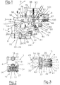
- FIGS. 1, 2, 3, 6 and 7 Figures 4, 5, 8, 9, 10, 11, 12 and 13 describe the mode of operation of the mechanisms and the injection valve of the rinsing; for this reason, Figures 4, 5, 8, 9, 10, 11, 12 and 13 bear the relative numerical references the operation of the injection mechanisms and valve.
- Figures 1 and 7 show that the flushing device which is the subject of the invention comprises a mechanism for attachment 1, an injection valve 2, a rinsing 3 and means 4 for collecting liquid residual rinse, which are only shown on Figure 13.
- the fixing mechanisms 1 and rinse 3, as well as the injection valve 2, are arranged at the outer end 5 of the longitudinal support 6 whose internal end 7 is equipped with means allowing its coupling to the rinsing carousel.
- the fixing mechanism 1 comprises a base body 8, a guide roller 18 and fixing clamps 15.
- Figures 1 and 2 show that the base body 8 is consists of two half-bodies 9 in the shape of an approximate "U”, arranged face to face and in parallel, united by their ends corresponding to a connecting body respective 10, 11. Two of the opposite arms of the base body 8, i.e.
- the rotation arms 12 are each connected to one of the arms 13 of the longitudinal support 6 which are arranged inside as shown in Figure 1, the union being ensured by axes 14 which allow the basic body 8 to rotate back and forth in a angle of at least 180 °, as shown in Figures 8, 9 and 13; attached to the connecting body 18 which connects these arms 12, there is the suitable guide roller 18 to rotate between two concentric guides of the carousel, a prismatic guide 19 of cross section rectangular and another cylindrical guide 20 which, on its section corresponding to the fixing operation of a bottle 28 (see FIG. 7, 8, 9 and 13) present a rectangular cross section as shown Figure 1.
- Figures 2 and 3 show that the clamps 15 include two identical fixing levers 16, two guide pins 34, an opening body 21, a opening spring 22 and an opening roller 23.
- FIG 3 shows that the fixing levers 16, which are of the first kind, are arranged symmetrically by relative to the front arms 14, and each comprises an arm resistance or fixing 24, a fulcrum 29 and a force arm 30: the fixing arms 24 are arranged opposite the bottoms 25 of the half-bodies 9, and each from them is fixed a non-slip element 24 which, like the shown in detail in Figure 5, is adapted to the neck 27 of a bottle 28; the support points 29 are arranged on the connecting body 11; and the power arms 30 form a certain angle inward.
- the axes of guide 34 are fixed by one of their ends, that from inside 35, to the connecting body 11 which they protrude perpendicularly, as shown in the figure 3; these guide pins 34 are attached by their external ends 36 by means of a bridge 37 which makes stop function.
- the spring opening 22 is disposed between the guide pins 34 and works continuously in compression by pressing on one of its ends, that of the interior 40, housed in a cavity 33 against the connecting body 11, its other end, that of the exterior 41, being housed in the central hole 31, against a stop 42 of the opening body 21;
- the opening spring 22 has a core 17 which avoids deformation or buckling, and which is fixed by its internal end 32 to the cavity 33 of the connecting body 11; the core 17 is adapted from way to pass through the central hole 31 of the opening body 21 when it is moved.
- the elastic reaction of the opening spring 22 tends continually locating the opening body 21 in the position shown in Figure 3, position in which the action exerted by the opening grooves 39 on the power arms 30 of the fixing levers 16 locates the fixing arms 24 in the position of closing the clamps 15.
- the opening roller 23 is fixed to the opening body 21, perpendicularly disposed relative to the guide pins 34.
- FIG 3 shows the arrangement fixing clamps 15 when no pressure is exerted on the opening roller 23; as indicated above, under these conditions, the reaction of the opening spring 22 on the opening body 21 located the fixing arms 24 of the fixing lever 16 in closed position.
- the concentric guides 19, 20 describe a second helical turn in the opposite direction and, like the shows figure 13, the fixing mechanism 1 described in turn an angle of 180 ° in the direction indicated by the letter F and comes to place the bottle 28 in position vertical or outlet; it is in this position that the action of a stop, not shown, on the roller opening 23, causes opening as described above clamps 15 and allows the mechanism extraction of rinsed bottles 28 to make sound office; then, when this stop stops acting on the opening roller 23, fixing clamps 15 return to their initial position described above.
- Figure 6 shows that the injection valve 2 includes a main body 43, a guide body 44, a body of blocking 45, a closing body 46, two axes of blocking 47, two blocking springs 48, two springs closure 49, an opening axis 50 and a pipe flexible 51.
- the main body 43 includes two extensions transverse 52 of support 6, equal and parallel between them, (see side view, figure 1), united by their lower end 53 by means of a guide body 44, and having at their lower end 54 two supports angled 55 arranged face to face.
- the guide body 44 has a central hole 56 and two side holes 57, equal and located in the same alignment.
- the body of blocking 45 is elongated; at its end upper 58, it has two transverse extensions 59 each provided with an orifice 60 and a groove blocking 61, and, at its lower end 62, a closing seat 63.
- the closing body 46 is disposed transversely between the guide body 44 and the angled supports 55: at each end, it is coupled perpendicular to a locking pin 47; each of these locking pins passes through a lateral orifice 57 of the guide body 44 and an orifice 60 of the blocking body 45, and has a transverse projection 64 adapted to a seat 65 of the blocking body 45, so that when the injection valve 2 is in the closed position (see figure 6), it fixes the distance between the bodies of blocking 45 and closing 46; between the locking axes 47, there is a closing seat 65; and, axially, a pin 66 to which the end is coupled internal 67 of the opening axis 50, which allows it to rotate in both directions.
- the locking springs are arranged in alignment with the locking pins 47 and work continuously in compression, pressing a of their ends against a stop 68 disposed at the outer end 69 of the locking pin 47, and their other end against the blocking body 45.
- the closing springs 49 work continuously in compression, pressing one of their ends against the bottom 70 of one of the cavities 71 of the closure body 46, cavities arranged in alignment with the axis of blocking 47 which corresponds to them, and their other end against a respective bent spring 55.
- the injection valve 2 is provided with actuating means 72 which, as shown in Figure 6, are arranged at the outer end 73 of the opening axis 50 and include an opening roller 74 and two arms actuation 75 (see side view - Figure 1); each actuating arm 75 is connected by its ends, with the possibility of pivoting in both directions, one of the transverse extensions 52 of the main body 43 and at the outer end 73 of the opening axis 50, the whole being adapted so that the rotation of the roller 74 around the main body 43, in a one way or the other, causes vertical displacement of the closing body 46.
- actuating means 72 which, as shown in Figure 6, are arranged at the outer end 73 of the opening axis 50 and include an opening roller 74 and two arms actuation 75 (see side view - Figure 1); each actuating arm 75 is connected by its ends, with the possibility of pivoting in both directions, one of the transverse extensions 52 of the main body 43 and at the outer end 73 of the opening axis 50, the whole being adapted so that
- the injection valve 2 has blocking means 76 (see Figures 1, 6 and 7) which include two levers blocking 77 symmetrical and equal, arranged in relation to the longitudinal axis of the support 6, and a spring of recovery 78.
- the blocking levers 77 which are first genus, and, as shown in Figures 1 and 7, are located parallel to the support 6, take their fulcrum 79 at a relatively short distance from the injection valve 2;
- the main arm 80 which forms a certain inward angle is provided with a shirt 81;
- the resistant arm 82 which forms a certain angle inwards, is provided with an extension of blocking 83 (shown in section - Figure 6) suitable for remain engaged in the locking groove 61, between the blocking body 45 and the guide body 44 of the valve injection 2;
- the recovery spring 78 is joined by its ends to a force arm 82, so that it continuously tends to locate blocking extensions 83 in the locking grooves 61.
- FIG. 1 and 6 show the injection valve 2 in closed position, i.e. as it is located when no action is exerted on the opening roller; in these conditions, FIG. 6 shows that the flexible pipe 51 is compressed between the closing seats 63 and 65 of the blocking body 45 and closing body 46, preventing passage of rinse aid or air.
- the valve injection 2 should work as follows when it reaches the rinsing position.
- the fixing clips 15 of the fixing mechanism 1 must be in the position shown in Figure 3; in other words, the action of the opening spring 22 on the opening body 21 causes the approximation and the closing the fixing arms 24.
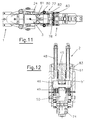
- the mechanism attachment 1 reaches the indicated rinsing position in FIG. 11, by pressing on the shirts 81 of the arm 80 of the locking levers 77, the arms of attachment 24 bring them together, then the separation of the resistance arms 82; its length increasing, the recovery spring 78 is therefore subject to stronger traction, and extensions blocking 83 are released from the locking grooves 61 of the injection valve 2.
- the action of the stop 85 on the opening roller 74 drives the axis opening 50 to turn in the direction indicated by the letter C (see Figure 9); therefore as the shows FIG. 12, the closing body 46 lowers, increasing the pressure on the closing springs 49, then the blocking body 45 in turn lowers under the action of the blocking springs 48 and comes to compress the flexible pipe 51, preventing the flushing liquid or seems to pass by and spread.
- the action that the stop 85 then exerts on the opening roller 74 causes, as indicated above, the rotation of the axis opening 50 in the direction indicated by the letter D (see figure 13) and the elevation of the closing bodies 46 and blocking 45, the flexible pipe 51 remaining compressed under the action of closing springs 49 and 48.
- Figure 1 shows that the flushing mechanism 3 includes a lever 88 of the first kind including the arm of force 89 is provided with a positioning roller 90 on which acts a stop 91, the fulcrum 92 of the lever being located on the support 6 between the end internal 7 and the injection valve 2; the resistant arm 93 includes a collecting tank 94 provided with a drain 95 leading to a collector not shown; a cannula 96 is connected to flexible line 51 and fixed on the tray 94.
- a housing 97 in which is placed a recovery spring 98 which works continuously in compression, pressing one of its ends against the main arm 89 by means of a socket 99, and its other end against the bottom 100 of the housing 97; given the arrangement of the recovery spring 98, the flushing mechanism 3 continuously tends to rotate in the direction indicated by the letter G (see figure 1), this circular movement being limited by a stop of positioning 101 placed at the front end 7 of the support 6.
- the flushing mechanism 3 operates as follows.
- the action that the stop 91 exerts on the position roller causes the lever to rotate 88 in the direction indicated by the letter H, which has for effect of bringing the recovery tank 94 and the cannula 96 in the position prior to the rinsing position; at the same time, its length decreasing, the spring recovery 98 is subjected to greater pressure.
- the stop 91 ceases to act on the positioning roller 90; the elastic reaction of the recovery spring 98 causes then the rotation of the lever 88 in the direction indicated by the letter G, the cannula 96 engages in the bottle 28 and the injection valve 2 injects the liquid therein rinse or air.
- stop 91 on the positioning roller 90 causes the lever 88 to rotate in the meaning indicated by the letter H and, after leaving the rinsing position, fixing mechanism 1 primer the movement indicated by the letter F to locate the bottle 28 in the out position. Then the stop 91 stops acting on the positioning roller 90. Consequently, the elastic reaction of the spring recovery 98 causes the lever 88 to rotate in the direction indicated by the letter G (see figure 9), and the rinsing mechanism 3 returns to the initial position shown in Figure 1.
- FIG. 13 shows that the collecting means 4 of the residual liquid include a suction line 102, permanently connected to a vacuum cleaner, not shown, and fixed to the cylindrical guide 20; at its end free 103, the suction line 102 has a suction nozzle 104.
- Line 102 and nozzle 104 suction are arranged so that they come stand between the rotation arms 12 and before 14 from base body 8, at a relatively short distance of the neck 27 of the bottle 28, when the mechanism of fixing 1 goes from the rinsing position to the position Release.
- a single line 102 has been shown, with its suction nozzle 104; however, depending on the scenario and their particular needs, especially when the density of the rinse aid used is very high, if necessary, it can be placed on the cylindrical guide 20 two or more suction lines 120 with their respective nozzles 104, regularly distributed along the helical path of the guide 20.
Landscapes
- Engineering & Computer Science (AREA)
- Mechanical Engineering (AREA)
- Filling Of Jars Or Cans And Processes For Cleaning And Sealing Jars (AREA)
- Cleaning In General (AREA)
Applications Claiming Priority (3)
| Application Number | Priority Date | Filing Date | Title |
|---|---|---|---|
| ES9600399 | 1996-02-21 | ||
| ES9600399A ES2127100B1 (es) | 1996-02-21 | 1996-02-21 | Dispositivo enjuagador de botellas, para maquinas rotativas. |
| PCT/ES1997/000039 WO1997030800A1 (es) | 1996-02-21 | 1997-02-20 | Dispositivo enjuagador de botellas, para maquinas rotativas |
Publications (1)
| Publication Number | Publication Date |
|---|---|
| EP0822013A1 true EP0822013A1 (de) | 1998-02-04 |
Family
ID=8293873
Family Applications (1)
| Application Number | Title | Priority Date | Filing Date |
|---|---|---|---|
| EP97904464A Ceased EP0822013A1 (de) | 1996-02-21 | 1997-02-20 | Vorrichtung zum waschen von flaschen für rotationsmaschinen |
Country Status (3)
| Country | Link |
|---|---|
| EP (1) | EP0822013A1 (de) |
| ES (1) | ES2127100B1 (de) |
| WO (1) | WO1997030800A1 (de) |
Cited By (1)
| Publication number | Priority date | Publication date | Assignee | Title |
|---|---|---|---|---|
| IT202200018582A1 (it) * | 2022-09-12 | 2024-03-12 | Mbf Spa | Macchina sciacquatrice per bottiglie e metodo di sciacquatura di bottiglie |
Families Citing this family (1)
| Publication number | Priority date | Publication date | Assignee | Title |
|---|---|---|---|---|
| ES2154976B1 (es) * | 1998-05-12 | 2001-11-16 | Desarrollos Tecnologicos Bando | Lavadora de productos envasados. |
Family Cites Families (4)
| Publication number | Priority date | Publication date | Assignee | Title |
|---|---|---|---|---|
| IT1141837B (it) * | 1980-09-05 | 1986-10-08 | M E C I Di Bianchini & Marchin | Perfezionamenti ad una macchina sciacquatrice automatica |
| DE4022486C1 (en) * | 1990-07-14 | 1991-08-08 | Hermann 8404 Woerth De Kronseder | Bottle reverser or inverter - uses gripping head opened and closed by first cam and swivelled by second cam |
| IT228052Y1 (it) * | 1992-06-30 | 1998-02-05 | Ave Spa Off | Pinza a ganasce mobili per la presa di bottiglie o similari, applica- bile preferibilmente su macchine sciacquatrici sterilizzatrici automa- |
| ES2072808B1 (es) * | 1993-02-05 | 1998-04-01 | Soler Singla Alberto | Dispositivo enjuagador de botellas para maquinas rotativas. |
-
1996
- 1996-02-21 ES ES9600399A patent/ES2127100B1/es not_active Expired - Fee Related
-
1997
- 1997-02-20 EP EP97904464A patent/EP0822013A1/de not_active Ceased
- 1997-02-20 WO PCT/ES1997/000039 patent/WO1997030800A1/es not_active Ceased
Non-Patent Citations (1)
| Title |
|---|
| See references of WO9730800A1 * |
Cited By (2)
| Publication number | Priority date | Publication date | Assignee | Title |
|---|---|---|---|---|
| IT202200018582A1 (it) * | 2022-09-12 | 2024-03-12 | Mbf Spa | Macchina sciacquatrice per bottiglie e metodo di sciacquatura di bottiglie |
| EP4335561A1 (de) * | 2022-09-12 | 2024-03-13 | MBF S.p.A. | Spülmaschine für flaschen und verfahren zum spülen von flaschen |
Also Published As
| Publication number | Publication date |
|---|---|
| WO1997030800A1 (es) | 1997-08-28 |
| ES2127100A1 (es) | 1999-04-01 |
| ES2127100B1 (es) | 1999-12-16 |
Similar Documents
| Publication | Publication Date | Title |
|---|---|---|
| EP0477352B2 (de) | Greifklemme und damit ausgerüstete behandlungsmaschine für gegenstände, insbesondere flaschen | |
| EP0477341B2 (de) | Vorrichtungen und maschine zum behandeln von flaschen | |
| FR2824542A1 (fr) | Pince de prehension de recipients et procede de transport correspondant | |
| FR2473024A1 (fr) | Procede et dispositif d'ouverture de produits formes de plusieurs feuilles, et unite de traitement utilisant le dispositif | |
| EP0884219B1 (de) | Bewegbare Trittstufe für ein Fahrzeug | |
| CH630192A5 (fr) | Boite d'entreposage de billets. | |
| FR2510453A1 (fr) | Appareil pour la fermeture d'attaches | |
| EP0614708A1 (de) | Spüleinrichtung für Flaschenreinigungsrundmaschinen | |
| EP0822013A1 (de) | Vorrichtung zum waschen von flaschen für rotationsmaschinen | |
| FR2668460A1 (fr) | Procede et dispositif d'amenee et de blocage de fil sur un dispositif de bobinage d'une machine textile. | |
| FR3108593A1 (fr) | Dispositif de transfert d'articles présentant des dimensions transversales variées et installation comprenant de tels dispositifs. | |
| FR2462904A1 (fr) | Appui-tete pour fauteuil de traitement, notamment fauteuil dentaire | |
| FR2650807A1 (fr) | Dispositif permettant l'ouverture et la fermeture de recipients ayant a vide une forme aplatie | |
| EP4582764A1 (de) | Anordnung zur positionierung und lagesicherung eines geschosses in einer mulde und ladehilfevorrichtung mit einer solchen anordnung | |
| CH645861A5 (fr) | Mecanisme pour prelever des billets un par un a partir d'une pile de billets. | |
| FR2489802A1 (fr) | Perfectionnements a une machine rinceuse automatique, notamment pour bouteilles | |
| EP1281343A1 (de) | Rollenhalterflansch zur Vermeidung von Schleifenbildung in einem Aufwischmaterialspender | |
| EP0549466A1 (de) | Vorrichtung zum Zuführen eines flachen Gegenstandes zu einer einrichtung zum Behandeln dieses Gegenstandes | |
| FR2689093A1 (fr) | Dispositif de sertissage de boîtes de conserve à grande cadence. | |
| FR2660982A1 (fr) | Dispositif de commande d'ecoulement. | |
| FR2478614A1 (fr) | Perfectionnements aux distributeurs de muselets | |
| FR2521525A1 (fr) | Poste d'etiquetage pour des objets tels que des bouteilles | |
| FR2570209A1 (fr) | Dispositif d'encaissement a echappement pour publiphones et autres appareils a prepaiement susceptibles de recevoir plusieurs types differents de pieces de monnaie | |
| FR2850306A1 (fr) | Mandrin pince | |
| FR2737125A1 (fr) | Support d'ensemble comportant une plaque dorsale et un element cylindrique fixe sur celle-ci |
Legal Events
| Date | Code | Title | Description |
|---|---|---|---|
| PUAI | Public reference made under article 153(3) epc to a published international application that has entered the european phase |
Free format text: ORIGINAL CODE: 0009012 |
|
| 17P | Request for examination filed |
Effective date: 19971105 |
|
| AK | Designated contracting states |
Kind code of ref document: A1 Designated state(s): DE ES FR IT |
|
| GRAG | Despatch of communication of intention to grant |
Free format text: ORIGINAL CODE: EPIDOS AGRA |
|
| 17Q | First examination report despatched |
Effective date: 20010627 |
|
| STAA | Information on the status of an ep patent application or granted ep patent |
Free format text: STATUS: THE APPLICATION HAS BEEN REFUSED |
|
| 18R | Application refused |
Effective date: 20020106 |