EP0822302A1 - Armoire de disribution pour des installations de chauffage et/ou de sanitaire - Google Patents
Armoire de disribution pour des installations de chauffage et/ou de sanitaire Download PDFInfo
- Publication number
- EP0822302A1 EP0822302A1 EP97112611A EP97112611A EP0822302A1 EP 0822302 A1 EP0822302 A1 EP 0822302A1 EP 97112611 A EP97112611 A EP 97112611A EP 97112611 A EP97112611 A EP 97112611A EP 0822302 A1 EP0822302 A1 EP 0822302A1
- Authority
- EP
- European Patent Office
- Prior art keywords
- distribution cabinet
- box
- rail
- vertical
- cabinet according
- Prior art date
- Legal status (The legal status is an assumption and is not a legal conclusion. Google has not performed a legal analysis and makes no representation as to the accuracy of the status listed.)
- Withdrawn
Links
- 238000010438 heat treatment Methods 0.000 title claims description 3
- 238000009434 installation Methods 0.000 title claims description 3
- 238000009826 distribution Methods 0.000 claims abstract description 31
- 229920003023 plastic Polymers 0.000 claims abstract description 9
- 239000004033 plastic Substances 0.000 claims abstract description 9
- 239000011324 bead Substances 0.000 claims description 7
- 210000002105 tongue Anatomy 0.000 claims description 6
- 239000002184 metal Substances 0.000 claims description 3
- 230000002093 peripheral effect Effects 0.000 abstract 1
- 230000003014 reinforcing effect Effects 0.000 abstract 1
- 238000005553 drilling Methods 0.000 description 3
- 239000000463 material Substances 0.000 description 2
- 229910000831 Steel Inorganic materials 0.000 description 1
- 238000010276 construction Methods 0.000 description 1
- 238000005520 cutting process Methods 0.000 description 1
- 238000006073 displacement reaction Methods 0.000 description 1
- 238000004519 manufacturing process Methods 0.000 description 1
- 239000007769 metal material Substances 0.000 description 1
- 238000000034 method Methods 0.000 description 1
- 239000011505 plaster Substances 0.000 description 1
- 239000010959 steel Substances 0.000 description 1
- 239000013589 supplement Substances 0.000 description 1
- 238000009966 trimming Methods 0.000 description 1
Images




Classifications
-
- E—FIXED CONSTRUCTIONS
- E04—BUILDING
- E04F—FINISHING WORK ON BUILDINGS, e.g. STAIRS, FLOORS
- E04F19/00—Other details of constructional parts for finishing work on buildings
- E04F19/08—Built-in cupboards; Masks of niches; Covers of holes enabling access to installations
-
- F—MECHANICAL ENGINEERING; LIGHTING; HEATING; WEAPONS; BLASTING
- F24—HEATING; RANGES; VENTILATING
- F24D—DOMESTIC- OR SPACE-HEATING SYSTEMS, e.g. CENTRAL HEATING SYSTEMS; DOMESTIC HOT-WATER SUPPLY SYSTEMS; ELEMENTS OR COMPONENTS THEREFOR
- F24D19/00—Details
- F24D19/0097—Casings or frame structures for hydraulic components
Definitions
- the invention relates to a distribution cabinet for sanitary and / or heating installations with a back wall and at least three frame legs having box and a door frame which can be fixed to the box with a Door, and the distribution cabinet can be fixed in a masonry and below the door frame, a cover panel is provided and within the box and behind the cover panel is a pipe guide rail is arranged and undercuts facing the receiving space on the rear wall of the box are provided for the arrangement of brackets.
- Distribution cabinets for the purpose mentioned have become known in many versions (DE-GM 91 12 410; DE-GM 19 85 358; AT-GM 745 U1). Especially In this context, the previously known construction should be mentioned (DE 32 16 832 A1), which can be used in masonry and can be locked with a door and which has a wall anchor.
- the plastic box of the Distribution cabinet is deep-drawn and has an advanced heel Plaster size on.
- the box is stiffened by transverse ribs and has its rear wall Undercuts for the arrangement of holding brackets for the bracket the pipes are required.
- the invention aims to one To further develop this type of distribution cabinet so that it is as possible can be manufactured inexpensively and is still so stable and stiff is that it can be used directly in masonry without the need for him intended receiving opening in the masonry a load-bearing lintel beam needed, so the distribution cabinet can be walled immediately.
- the invention proposes that the plastic Box is deep drawn and that to hold the door frame, which is used as a pipe guide serving rail and the cover panel separately manufactured fittings provided are and to stiffen the upper frame leg on this one deep-drawn, plastic rail is attached.
- the distribution cabinet 1 consists of a thermoformed made of plastic Box 2 with a profiled rear wall 3 and three frame legs 3, these three frame legs serving as a plastering bead 5 have.
- a profile rail 6 is provided (Fig. 21 to Fig. 23) with trough-like depressions and one surrounding the profile rail 6 on three sides Edge 7, which the profile rail 6 on the upper horizontal frame leg 4 of the Box 2 holds in a predetermined position.
- this rail 6 which serves to stiffen the upper horizontal frame leg, can also be made of metallic materials such as steel.
- the box 2 which is open at the bottom, carries a cover panel 8 with two horizontal, against the inside of the box 2 beads 9, which delimit a groove.
- U-shaped profile pieces 12 are provided with a vertical axis. These profile pieces 2 have 13 undercuts 14 on their lateral legs, and each of these Undercuts are equipped with a row of holes 15. This on the vertical Frame legs 4 attached profile pieces 12 are used to hold each an L-shaped fastening fitting 16, in its horizontal leg 17th Provided here not shown mounting holes for mounting screws are.
- the congruent with the undercuts 14 of the profile piece 12 Portions of the vertical leg 18 are bent up as tabs 19 trained to carry the bolt 40, the diameter of which corresponds to the diameter of the holes correspond to row of holes 5.
- the width B of these tabs 19 is expedient slightly larger than the width b of the undercuts 14.
- the mounting bracket 16 is inserted into the rail 12, with its vertical leg 18, the bent-up tabs 19 being pushed back are.
- the pressed back tabs 19 can be held in this position are due to the specified dimensional ratios of the widths above are mentioned. That pair of holes in the rows of holes 15 is then selected, through which the distribution cabinet is aligned as horizontally as possible is possible on the floor of the building.
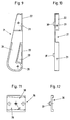
- Profile piece 41 has a base plate 42 provided in the corner areas Bores 43 for receiving fasteners. On this base plate 42 are in horizontally spaced from each other, two vertical cross-sectionally U-shaped groove-like guides 44 are provided, these guides in the bottom of the groove 44 rows of holes 45 are recessed.
- This profile piece 41 is used for recording of the mounting bracket 46, which has a horizontal base plate 47 Recesses 48 for receiving fasteners and two vertical legs 49 having. The free ends of these legs 49 are through longitudinal incisions 51 resilient tongues 50 formed. These resilient tongues are on the back 50 each have a wedge-like extension 52.
- the legs 49 are in their base region provided with cutouts 53 so that this mounting bracket 46 by can be used above in the profile piece 41. Then the mounting bracket 46 pulled down relative to this profile piece 41, the engage wedge-like projections 52 on the resilient tongues 50 into the bores 43. The wedge shape of the lugs 52 means that the fastening fitting is pushed back 46 prevented upwards.
- the distance between the two longitudinal incisions 51 of a leg 49 corresponds approximately to the opening width of the U-shaped guides 44. This distance limits the width of the resilient tongue 50, which are dimensioned in this way is that they are compared to the displacement of the mounting bracket 46 the profile piece 41 can dodge within the U-shaped guide 44, and in the space between these guides that is left out of the side legs 44.
- the Fitting 21 according to Figures 9 and 10 provided.
- This is mainly in Fitting 21 extending vertically has a flange 22 which is substantially lies flush with the plane of the front opening of the box 2.
- bores 23 are provided in this flange for receiving fastening screws, with which the cover 8 can be screwed.
- This fitting 21 also has a substantially vertical, towards the center of the Box 2 open channel 24, the lower end of which to form a snap-in receptacle 25 is angled for the rod-shaped rail 20.
- a metal sheet 26 is attached, the upper one Edge and its lower edge flanged to form undercuts 27 are. These flanges accommodate brackets on which the here Pipes, lines and fittings, not shown, are attached.
- the box 2 can be closed with a door 28, which is also made of plastic and which is constructed with two shells in order to make them as rigid as possible and to make it resistant.
- the outer shell 29 is flat and has flanged Edges, the lower flanged edge 30 as a hinge strip serves.
- the inner shell 31 is profiled, here in the manner of a checkerboard pattern.
- the two shells 29 and 31 are expediently glued.
- To record the door 28 a door frame is provided, which is also made of plastic material is made, with its stiffening on the profile strips (Fig. 14 and Fig. 15) the frame leg metallic profile strips 33 are glued.
- a fork-like holder 35 is arranged, which cooperates with the fitting 36, which is on the inside of the vertical Frame leg 4 of the box 2 is arranged.
- This fork-like holder 35 engages in the cross-sectionally U-shaped fitting 36 and is here by a screw, not shown, which is received by the bore 37, held.
- the door frame opposite the box 2 because the fork-like holder on the vertical frame legs of the door frame 32 are hinged like a hinge.
- the door 28 is flanged with its edge, which serves as a hinge strip 30 hung in the frame.
- the box 2 is placed on the floor of a building and over the Profile pieces 12 and the fittings 16 aligned therein, and then are screws in the holes provided in the horizontal leg 17 inserted and screwed into the floor of the building.
- the through the profile rail 6 stiffened and reinforced box 2 is then walled without one Crashbar must be used.
- the cables are drawn in and installed.
- the lower frame leg 11 Cut out according to the drawn-in cables and then insert them and fixed by the cover 8 to be screwed on.
- the door frame 32 is mounted, then the door is hung and locked. This assembly work takes place at larger intervals, which depend on the time in which the structure is erected, in which this distribution cabinet is used.
- fittings 21 and 36 have these on their back pins 39, the corresponding from recessed in the box 2 Openings are included.
- these Fittings on box 2 can profile these pins or their cross section be, or the pin can be arranged so that the fittings only in one intended orientation relative to the box 2 can be determined on this, thereby avoiding incorrect assembly.
- frame legs 4 can also not shown here, of lines of weakness delimited or limited areas are provided for education punctured by cable feed-through openings and broken out.
Landscapes
- Engineering & Computer Science (AREA)
- Architecture (AREA)
- Civil Engineering (AREA)
- Structural Engineering (AREA)
- Assembled Shelves (AREA)
- Patch Boards (AREA)
Applications Claiming Priority (2)
| Application Number | Priority Date | Filing Date | Title |
|---|---|---|---|
| AT44396U AT1609U1 (de) | 1996-07-29 | 1996-07-29 | Verteilerschrank für sanitär- und/oder heizungsinstallationen |
| AT443/96 | 1996-07-29 |
Publications (1)
| Publication Number | Publication Date |
|---|---|
| EP0822302A1 true EP0822302A1 (fr) | 1998-02-04 |
Family
ID=3490754
Family Applications (1)
| Application Number | Title | Priority Date | Filing Date |
|---|---|---|---|
| EP97112611A Withdrawn EP0822302A1 (fr) | 1996-07-29 | 1997-07-23 | Armoire de disribution pour des installations de chauffage et/ou de sanitaire |
Country Status (2)
| Country | Link |
|---|---|
| EP (1) | EP0822302A1 (fr) |
| AT (1) | AT1609U1 (fr) |
Cited By (3)
| Publication number | Priority date | Publication date | Assignee | Title |
|---|---|---|---|---|
| EP1477744A2 (fr) | 2003-05-14 | 2004-11-17 | EUT Edelstahl Umformtechnik GmbH | Armoire de distribution |
| EP3312518A1 (fr) * | 2016-10-24 | 2018-04-25 | REHAU AG + Co | Dispositif de montage du distributeur de fluide |
| PL131647U1 (pl) * | 2023-09-06 | 2025-03-10 | Defro R. Dziubeła Spółka Komandytowa | Szafka podtynkowa do rozdzielacza obwodów grzewczych |
Families Citing this family (1)
| Publication number | Priority date | Publication date | Assignee | Title |
|---|---|---|---|---|
| AT2497U1 (de) * | 1997-11-06 | 1998-11-25 | Kuyper Ivo | Verteilerkasten |
Citations (1)
| Publication number | Priority date | Publication date | Assignee | Title |
|---|---|---|---|---|
| AT745U1 (de) * | 1995-06-12 | 1996-04-25 | Bruggisser Alexander | Verteilerschrank für sanitär- und/oder heizungsinstallationen |
Family Cites Families (1)
| Publication number | Priority date | Publication date | Assignee | Title |
|---|---|---|---|---|
| DE3216832A1 (de) * | 1982-05-05 | 1984-03-22 | Thyssen Plastik Anger KG, 8000 München | Installationskasten |
-
1996
- 1996-07-29 AT AT44396U patent/AT1609U1/de not_active IP Right Cessation
-
1997
- 1997-07-23 EP EP97112611A patent/EP0822302A1/fr not_active Withdrawn
Patent Citations (1)
| Publication number | Priority date | Publication date | Assignee | Title |
|---|---|---|---|---|
| AT745U1 (de) * | 1995-06-12 | 1996-04-25 | Bruggisser Alexander | Verteilerschrank für sanitär- und/oder heizungsinstallationen |
Cited By (5)
| Publication number | Priority date | Publication date | Assignee | Title |
|---|---|---|---|---|
| EP1477744A2 (fr) | 2003-05-14 | 2004-11-17 | EUT Edelstahl Umformtechnik GmbH | Armoire de distribution |
| EP1477744A3 (fr) * | 2003-05-14 | 2005-08-03 | EUT Edelstahl Umformtechnik GmbH | Armoire de distribution |
| EP1477744B1 (fr) | 2003-05-14 | 2016-08-31 | EUT Edelstahl Umformtechnik GmbH | Armoire de distribution |
| EP3312518A1 (fr) * | 2016-10-24 | 2018-04-25 | REHAU AG + Co | Dispositif de montage du distributeur de fluide |
| PL131647U1 (pl) * | 2023-09-06 | 2025-03-10 | Defro R. Dziubeła Spółka Komandytowa | Szafka podtynkowa do rozdzielacza obwodów grzewczych |
Also Published As
| Publication number | Publication date |
|---|---|
| AT1609U1 (de) | 1997-08-25 |
Similar Documents
| Publication | Publication Date | Title |
|---|---|---|
| DE10136681C2 (de) | Rahmengestell | |
| DE3711609A1 (de) | Duschabtrennung | |
| DE19748679C1 (de) | Befestigung eines Türblatts an einer Gerätetür | |
| EP0384224B1 (fr) | Dispositif de guidage | |
| DE2558358C2 (de) | Vorsatzfenster | |
| AT526489B1 (de) | Oberer Querholm für eine Duschabtrennung | |
| AT1609U1 (de) | Verteilerschrank für sanitär- und/oder heizungsinstallationen | |
| DE19643102A1 (de) | Duschabtrennung | |
| DE10134396C1 (de) | Bausatz zum Einsetzen eines Wandelementes in eine Wandöffnung einer doppelschaligen Ständerwand | |
| EP0115554B1 (fr) | Dispositif pour le revêtement d'un châssis de porte | |
| DE102005025821A1 (de) | Beschlag für Falt-Schiebewand | |
| DE4409155A1 (de) | Verbindungselement zur Verbindung von plattenförmigen Wandelementen | |
| EP1748143A2 (fr) | Dispositif pour fermer des ouvertures de bâtiments | |
| DE69002041T2 (de) | Montagesystem und montageelemente für trennwände in bürogebäuden und dergleichen. | |
| EP4026979B1 (fr) | Installation de porte hermétique | |
| EP4001531B1 (fr) | Ensemble pour une cabane à outils | |
| DE3426831A1 (de) | Aus vorgefertigten wand- und deckentafeln bestehendes raumbausystem fuer schiffe und aehnliche baukoerper | |
| EP0213451A2 (fr) | Rail pour une construction de support d'un bardage de mur ou plafond | |
| EP0835979B1 (fr) | Volet roulant et son cache intérieure | |
| EP2304151B1 (fr) | Profilé de cadre, dormant et cadre de porte de garage | |
| DE19940168C2 (de) | Aus Blech hergestelltes Plattenelement | |
| AT524994A2 (de) | Bausatz für ein Gerätehaus | |
| DE1961348C (de) | Befestigung einer Eckumlenkung für Treibstangenverschlüsse von Fenstern, Türen od. dgl | |
| DE29916580U1 (de) | Bausatz für Metallbox | |
| DE2534320A1 (de) | Aus mindestens zwei teilen bestehende profilschiene |
Legal Events
| Date | Code | Title | Description |
|---|---|---|---|
| PUAI | Public reference made under article 153(3) epc to a published international application that has entered the european phase |
Free format text: ORIGINAL CODE: 0009012 |
|
| AK | Designated contracting states |
Kind code of ref document: A1 Designated state(s): AT CH DE LI |
|
| AX | Request for extension of the european patent |
Free format text: AL;LT;LV;RO;SI |
|
| 17P | Request for examination filed |
Effective date: 19980803 |
|
| AKX | Designation fees paid |
Free format text: AT CH DE LI |
|
| RBV | Designated contracting states (corrected) |
Designated state(s): AT CH DE LI |
|
| GRAG | Despatch of communication of intention to grant |
Free format text: ORIGINAL CODE: EPIDOS AGRA |
|
| 17Q | First examination report despatched |
Effective date: 19981202 |
|
| GRAG | Despatch of communication of intention to grant |
Free format text: ORIGINAL CODE: EPIDOS AGRA |
|
| GRAH | Despatch of communication of intention to grant a patent |
Free format text: ORIGINAL CODE: EPIDOS IGRA |
|
| STAA | Information on the status of an ep patent application or granted ep patent |
Free format text: STATUS: THE APPLICATION IS DEEMED TO BE WITHDRAWN |
|
| 18D | Application deemed to be withdrawn |
Effective date: 19990622 |