EP0824186A2 - Système de commande pour un moteur à combustion interne - Google Patents
Système de commande pour un moteur à combustion interne Download PDFInfo
- Publication number
- EP0824186A2 EP0824186A2 EP97113156A EP97113156A EP0824186A2 EP 0824186 A2 EP0824186 A2 EP 0824186A2 EP 97113156 A EP97113156 A EP 97113156A EP 97113156 A EP97113156 A EP 97113156A EP 0824186 A2 EP0824186 A2 EP 0824186A2
- Authority
- EP
- European Patent Office
- Prior art keywords
- fuel
- engine
- rotational speed
- mode
- injection mode
- Prior art date
- Legal status (The legal status is an assumption and is not a legal conclusion. Google has not performed a legal analysis and makes no representation as to the accuracy of the status listed.)
- Granted
Links
Images


Classifications
-
- F—MECHANICAL ENGINEERING; LIGHTING; HEATING; WEAPONS; BLASTING
- F02—COMBUSTION ENGINES; HOT-GAS OR COMBUSTION-PRODUCT ENGINE PLANTS
- F02D—CONTROLLING COMBUSTION ENGINES
- F02D41/00—Electrical control of supply of combustible mixture or its constituents
- F02D41/02—Circuit arrangements for generating control signals
- F02D41/04—Introducing corrections for particular operating conditions
- F02D41/08—Introducing corrections for particular operating conditions for idling
-
- F—MECHANICAL ENGINEERING; LIGHTING; HEATING; WEAPONS; BLASTING
- F02—COMBUSTION ENGINES; HOT-GAS OR COMBUSTION-PRODUCT ENGINE PLANTS
- F02D—CONTROLLING COMBUSTION ENGINES
- F02D41/00—Electrical control of supply of combustible mixture or its constituents
- F02D41/30—Controlling fuel injection
-
- F—MECHANICAL ENGINEERING; LIGHTING; HEATING; WEAPONS; BLASTING
- F02—COMBUSTION ENGINES; HOT-GAS OR COMBUSTION-PRODUCT ENGINE PLANTS
- F02D—CONTROLLING COMBUSTION ENGINES
- F02D41/00—Electrical control of supply of combustible mixture or its constituents
- F02D41/02—Circuit arrangements for generating control signals
- F02D41/04—Introducing corrections for particular operating conditions
- F02D41/12—Introducing corrections for particular operating conditions for deceleration
- F02D41/123—Introducing corrections for particular operating conditions for deceleration the fuel injection being cut-off
-
- F—MECHANICAL ENGINEERING; LIGHTING; HEATING; WEAPONS; BLASTING
- F02—COMBUSTION ENGINES; HOT-GAS OR COMBUSTION-PRODUCT ENGINE PLANTS
- F02D—CONTROLLING COMBUSTION ENGINES
- F02D41/00—Electrical control of supply of combustible mixture or its constituents
- F02D41/30—Controlling fuel injection
- F02D41/3011—Controlling fuel injection according to or using specific or several modes of combustion
- F02D41/3017—Controlling fuel injection according to or using specific or several modes of combustion characterised by the mode(s) being used
- F02D41/3023—Controlling fuel injection according to or using specific or several modes of combustion characterised by the mode(s) being used a mode being the stratified charge spark-ignited mode
- F02D41/3029—Controlling fuel injection according to or using specific or several modes of combustion characterised by the mode(s) being used a mode being the stratified charge spark-ignited mode further comprising a homogeneous charge spark-ignited mode
-
- F—MECHANICAL ENGINEERING; LIGHTING; HEATING; WEAPONS; BLASTING
- F02—COMBUSTION ENGINES; HOT-GAS OR COMBUSTION-PRODUCT ENGINE PLANTS
- F02D—CONTROLLING COMBUSTION ENGINES
- F02D41/00—Electrical control of supply of combustible mixture or its constituents
- F02D41/30—Controlling fuel injection
- F02D41/38—Controlling fuel injection of the high pressure type
- F02D41/40—Controlling fuel injection of the high pressure type with means for controlling injection timing or duration
- F02D41/401—Controlling injection timing
-
- F—MECHANICAL ENGINEERING; LIGHTING; HEATING; WEAPONS; BLASTING
- F02—COMBUSTION ENGINES; HOT-GAS OR COMBUSTION-PRODUCT ENGINE PLANTS
- F02D—CONTROLLING COMBUSTION ENGINES
- F02D41/00—Electrical control of supply of combustible mixture or its constituents
- F02D41/30—Controlling fuel injection
- F02D41/38—Controlling fuel injection of the high pressure type
- F02D2041/389—Controlling fuel injection of the high pressure type for injecting directly into the cylinder
-
- F—MECHANICAL ENGINEERING; LIGHTING; HEATING; WEAPONS; BLASTING
- F02—COMBUSTION ENGINES; HOT-GAS OR COMBUSTION-PRODUCT ENGINE PLANTS
- F02D—CONTROLLING COMBUSTION ENGINES
- F02D41/00—Electrical control of supply of combustible mixture or its constituents
- F02D41/22—Safety or indicating devices for abnormal conditions
-
- F—MECHANICAL ENGINEERING; LIGHTING; HEATING; WEAPONS; BLASTING
- F02—COMBUSTION ENGINES; HOT-GAS OR COMBUSTION-PRODUCT ENGINE PLANTS
- F02D—CONTROLLING COMBUSTION ENGINES
- F02D41/00—Electrical control of supply of combustible mixture or its constituents
- F02D41/30—Controlling fuel injection
- F02D41/3011—Controlling fuel injection according to or using specific or several modes of combustion
- F02D41/3076—Controlling fuel injection according to or using specific or several modes of combustion with special conditions for selecting a mode of combustion, e.g. for starting, for diagnosing
-
- Y—GENERAL TAGGING OF NEW TECHNOLOGICAL DEVELOPMENTS; GENERAL TAGGING OF CROSS-SECTIONAL TECHNOLOGIES SPANNING OVER SEVERAL SECTIONS OF THE IPC; TECHNICAL SUBJECTS COVERED BY FORMER USPC CROSS-REFERENCE ART COLLECTIONS [XRACs] AND DIGESTS
- Y02—TECHNOLOGIES OR APPLICATIONS FOR MITIGATION OR ADAPTATION AGAINST CLIMATE CHANGE
- Y02T—CLIMATE CHANGE MITIGATION TECHNOLOGIES RELATED TO TRANSPORTATION
- Y02T10/00—Road transport of goods or passengers
- Y02T10/10—Internal combustion engine [ICE] based vehicles
- Y02T10/40—Engine management systems
Definitions
- the present invention relates to a control system for an intra-cylinder injection type internal combustion engine in which fuel is injected directly into a combustion chamber.
- it is intended to prevent deterioration of combustion and thereby improve the fuel economy.
- intra-cylinder injection type multi-cylinder engines in which fuel is injected directly into a combustion chamber (see, for example, Japanese Patent Laid Open No.240044/93).
- a change-over is made between a suction stroke injection mode in which fuel injection is performed mainly in the suction stroke and a compression stroke injection mode in which fuel injection is performed mainly in the compression stroke, according to operating conditions.
- a control for stopping the supply of fuel to a combustion chamber of the engine according to operating conditions takes place, and a decision rotational speed for starting the cut-off of fuel in a fuel cut-off mode, as well as a fuel return rotational speed for returning from the fuel cut-off mode and restarting the supply of fuel, are preset to predetermined rotational speeds.
- Idling speed is also preset to a predetermined rotational speed. The decision rotational speed, the fuel return rotational speed, and the idling speed are set according to whether a transmission is a manual or an automatic and also according to whether the operation of an air conditioner or any other auxiliary device.
- a decision rotational speed for starting the cut-off of fuel is set according to whether an air conditioner or any other auxiliary device is on or off. Further, at each of neutral position in the manual and automatic transmissions and a drive position in the automatic transmission, an idling speed is set according to whether the operation of an air conditioner or any other auxiliary device is on or off.
- an optimum rotational speed according to the type of a transmission and the state of its operation is obtained, whereby it is possible to improve the fuel economy.
- a fuel cut-off mode is practiced according to the state of operation, and a decision rotational speed which permits the start of fuel cut-off on a low engine speed side, a fuel return rotational speed, and further an idling speed are set finely, according to the operating conditions, to improve the fuel economy. Improvement of the fuel economy is also obtained by setting the air-fuel ratio on a leaner side than the stoichiometric ratio, that is, by setting it at a lean air-fuel ratio. Recently, however, the demand for energy saving has become more and more keen, and a further improvement of fuel economy is now desired even for an intra-cylinder injection type multi- cylinder engine.
- the present invention has been accomplished in view of the above-mentioned circumstances and it is an object of the invention to provide a control system for internal combustion engine which improves the fuel economy without deterioration of combustion.
- a control system for internal combustion engine comprising:
- idling speed in the compression stroke injection mode superior in both combustion and responsivity is set lower than the idling speed in the suction stroke injection mode, idling is set at a low engine speed during operation in the compression stroke injection mode. As a result, a fuel economy can be improved without deterioration of combustion.
- the injection mode selecting means selects the compression stroke injection mode in a normal operating condition of the internal combustion engine and selects the suction stroke injection mode in a specific operating condition of the engine.
- the specific operating condition indicates a low temperature condition of the internal combustion engine or a fail safe condition against a trouble of at least one of various sensors or a trouble of a control based on the outputs of various sensors.
- the idling speed setting means sets the first and second target idling speeds according to operating conditions of a load member which exerts an influence on an output of the internal combustion engine and which is driven by an output shaft of the engine.
- the internal combustion engine is provided with temperature detecting means for detecting temperature of the engine, wherein the idling speed setting means sets respectively the first and second target idling speeds on the basis of the temperature detected by the temperature detecting means.
- the idling speed setting means sets respectively the first and second target idling speeds at lower speeds than on a low engine temperature side.
- a control system for internal combustion engine comprising:
- the return rotational speed for return from the fuel cut-off mode and restarting the supply of fuel is set in each of the suction stroke injection mode and the compression stroke injection mode, and the return rotational speed in the compression stroke injection mode, superior in both combustion and responsivity, is set lower than that in the suction stroke injection mode. Therefore, during operation in the compression stroke injection mode, the fuel cut-off mode can be practiced at a low rotational speed. As a result, fuel economy can be improved without deterioration of combustion.
- the injection mode selecting means selects the compression stroke injection mode in a normal operating condition of the internal combustion engine, while in a specific operating condition of the engine, the injection mode selecting means selects the suction stroke injection mode.
- the specific operating condition indicates a low temperature condition of the internal combustion engine or a fail safe condition against some trouble of any one of various sensors or some trouble in the control based on outputs of the various sensors.
- the internal combustion engine has a plurality of cylinders, and at the time of restarting the supply of fuel for return from the fuel cut-off mode to the compression stroke injection mode, the return rotational speed setting means sets the return rotational speed for restarting the supply of fuel to any of the plural cylinders at a higher level by a predetermined value than the first return rotational speed.
- the internal combustion engine is provided with fuel cut-off lower-limit rotational speed setting means for setting a first fuel cut-off lower-limit rotational speed which, at a low rotational speed of the engine, permits change-over from the compression stroke injection mode to the fuel cut-off mode, and for setting a second fuel cut-off lower-limit rotational speed which, at the above low rotational speed of the engine, permits change-over from the suction stroke injection mode to the fuel cut-off mode, wherein the fuel cut-off lower-limit rotational speed setting means setting the first fuel cut-off lower-limit rotational speed lower than the second fuel cut-off lower-limit rotational speed.
- the return rotational speed setting means selectively sets the first and second return rotational speeds according to operating conditions of a load member which exerts an influence on an output of the internal combustion engine and which is driven by an output shaft of the engine.
- the internal combustion engine is further provided with temperature detecting means for detecting temperature of the engine, wherein the return rotational speed setting means sets respectively the first and second return rotational speeds on the basis of the temperature detected by the temperature detecting means.
- the return rotational speed setting means sets respectively the first and second return rotational speeds at a lower value on a high engine temperature side than on a low engine temperature side.
- a control system for internal combustion engine comprising:
- the lower-limit rotational speed which permits the start of fuel cut-off on the low engine speed side is set in each of the suction stroke injection mode and the compression stroke injection mode, and the first fuel cut-off lower-limit rotational speed in the compression stroke injection mode superior in both combustion and responsivity is set lower than the second fuel cut-off lower-limit rotational speed in the suction stroke injection mode. Accordingly, during operation in the compression stroke injection mode, the fuel cut-off mode can be practiced on the low rotational speed side. As a result, not only the fuel cut-off mode can be practiced on the low engine speed side, but also a fuel economy can be improved without deterioration of combustion.
- the fuel cut-off lower-limit rotational speed setting means selectively sets the first and second fuel cut-off lower-limit rotational speeds according to operating conditions of a load member which exerts an influence on an output of the internal combustion engine and which is driven by an output shaft of the engine.
- the internal combustion engine is an intra-cylinder injection type multi-cylinder internal combustion engine in which fuel is injected directly into a combustion chamber.
- the intra-cylinder injection type multi-cylinder internal combustion engine to which the control system is applied is an intra-cylinder injection type straight four-cylinder gasoline engine (intra-cylinder injection engine) 1 in which fuel is injected directly into a combustion chamber.
- intra-cylinder injection engine 1 a combustion chamber, an intake device, and an exhaust gas recirculation device (EGR device) are specially designed for intra-cylinder injection.
- EGR device exhaust gas recirculation device
- a spark plug 3 is mounted on a cylinder head 2 of the intra-cylinder injection engine 1, and also mounted for each cylinder to the cylinder head is an electromagnetic type fuel injection valve 4 which serves as fuel supply means.
- a nozzle of the fuel injection valve 4 is open into a combustion chamber 5 so that a fuel injected from the fuel injection valve 4 through a driver 20 is directed into the combustion chamber 5 directly.
- a piston 7 is fitted vertically slidably into each cylinder 6 of the engine 1, with a semispherically recessed cavity 8 being formed in the top portion of the piston 7.
- the cavity 8 promotes the generation of a reverse tumble flow (a clockwise intake flow in the combustion chamber 5 in Fig.1) reverse to the ordinary intake tumble flow from an intake port which will be described later.
- an intake port 9 and an exhaust port 10 both facing the combustion chamber 5 are formed.
- the intake port 9 is opened and closed by an operation of an intake valve 11, while the exhaust port 10 is opened and closed by an operation of an exhaust valve 12.
- an intake-side cam shaft 13 and an exhaust-side cam shaft 14 are rotatably supported.
- the intake valve 11 is operated by a rotation of the intake-side cam shaft 13, while the exhaust valve 12 is operated by a rotation of the exhaust-side cam shaft 14.
- An exhaust gas recirculation portion (EGR port) 15 of a large diameter is branched obliquely downward from the exhaust port 10.
- a water temperature sensor 16 for detecting the temperature of a cooling water is disposed near the cylinders 6 of the intra-cylinder injection engine 1. Also provided is a crank angle sensor 17 of a vane type which outputs a crank angle signal SGT at a predetermined crank position (e.x. 75° BTDC and 5° BTDC)in each cylinder. The crank angle sensor 17 can also detect the engine speed.
- the cam shafts 13 and 14, which rotate at 1/2 revolutions of the cam shaft, are each provided with a discrimination sensor 18 which outputs a cylinder identification signal SGC. With the cylinder identification signal SGC it is made possible to discriminate of which cylinder the crank angle signal SGT is.
- the numeral 19 denotes an ignition coil for applying a high voltage to the spark plug 3.
- An intake pipe 40 is connected to the intake port 9 through an intake manifold 21, and a surge tank 22 is provided in the intake manifold 21.
- the intake pipe 40 is provided with an air cleaner 23, a throttle body 24, a first air bypass valve 25 of a stepping motor type, and an air flow sensor 26.
- the air flow sensor 26 which is for detecting the amount of intake air, a karman vortex type flow sensor is used, for example. If a boost pressure sensor is attached to the surge tank 22, the amount of intake air can be determined from the difference between an intake pipe pressure detected by the boost pressure sensor and the atmospheric pressure and also from the engine speed.
- an air bypass pipe 27 of a large diameter for intaking air to the intake manifold 21 while bypassing the throttle body 24.
- the air bypass pipe 27 is provided with a second air bypass valve 28 of a linear solenoid type.
- the air bypass pipe 27 has a flow path area corresponding to that of the intake pipe 40, so that, when the second air bypass valve 28 is fully open, it is possible to intake air in an amount required in low and medium speed ranges of the intra-cylinder injection engine 1.
- the throttle body 24 is provided with a butterfly type throttle valve 29 for opening and closing the flow path and is also provided with a throttle position sensor 30 for detecting the degree of opening of the throttle valve 29.
- the throttle position sensor 30 outputs a throttle voltage proportional to the degree of opening of the throttle valve 29.
- the throttle body 24 is further provided with an idle switch 31 for detecting a fully closed state of the throttle valve 29 and perceiving an idling state of the engine 1.
- an exhaust pipe 33 is connected to the exhaust port 10 through an exhaust manifold 32, and an O 2 sensor 34 is attached to the exhaust manifold 32.
- the exhaust pipe 33 is provided with a three-way catalytic converter 35 and a muffler (not shown).
- the EGR port 15 is connected to an upstream side of the intake manifold 21 through an EGR pipe 36 of a large diameter. Further, a stepping motor type EGR valve 37 is provided in the EGR pipe 36.
- Fuel is stored in a fuel tank 41 and it is sucked up by a low pressure fuel motor pump 42 and is fed to the engine 1 through a low pressure feed pipe 43.
- the pressure of the fuel present in the low pressure feed pipe 43 is adjusted to a relatively low pressure(low fuel pressure) by means of a first fuel pressure regulator 45 mounted on a return pipe 44.
- the fuel thus fed to the engine 1 is then fed to each fuel injection valve 4 through a high pressure feed pipe 47 and a delivery pipe 48 by means of a high pressure fuel pump 46.
- the high pressure fuel pump 46 is, for example, a swash plate type axial piston pump and is driven by the exhaust-side cam shaft 14 or the intake-side cam shaft 13 so that a discharge pressure of a predetermined level or higher can be generated even during idling of the engine 1.
- the fuel pressure in the delivery pipe 48 is adjusted to a relatively high pressure (high fuel pressure) by means of a second fuel pressure regulator 50 provided in a return pipe 49.
- An electromagnetic type fuel pressure change-over valve 51 is attached to the second fuel pressure regulator 50. When turned ON, the fuel pressure change-over valve 51 releases the fuel and can thereby decrease the fuel pressure in the delivery pipe 48.
- the numeral 52 in the figure denotes a return pipe for recirculating part of the fuel, which has been used for lubricating or cooling the high-pressure fuel pump 46, to the fuel tank 41.
- the vehicle concerned is provided with an electronic control unit (ECU) 61 as the control system.
- the ECU 61 is provided with an input/output device, a memory for storing control programs and control maps, a central processing unit, and timers and counters.
- An overall control for the engine 1 is performed by the ECU 61.
- Information detected by the sensors referred to above are inputted to the ECU 61, which in turn, in accordance with such information pieces, determines not only the fuel injection mode and the amount of fuel to be injected but also an ignition timing and the amount of EGR gas to be introduced, and controls the operation of the driver 20 for the fuel injection valve 4, the ignition coil 19, and EGR valve 37.
- the low pressure fuel pump 42 and the fuel pressure change-over valve 51 are turned ON and the fuel which is low in pressure is fed to the fuel injection valve 4.
- the engine 1 is cranked by means of a self starter motor (not shown) and at the same time a fuel injection control is started by the ECU 61.
- the ECU 61 selects a former-period injection mode (a fuel injection mode in the suction stroke), in which fuel is injected to give a relatively rich air-fuel ratio.
- the second air bypass valve 28 is substantially fully closed. Therefore, the intake of air to the combustion chamber 5 is performed through a clearance defined by the throttle valve 29 or through the first air bypass valve 25.
- the fuel pressure change-over valve 51 is turned off by the ECU 61, so that the fuel, which is high in pressure, is fed to the fuel injection valve 4.
- the amount of fuel to be injected is determined from, for example, the fuel pressure set for the second fuel pressure regulator 50, or the fuel pressure detected by the fuel pressure sensor which detects the fuel pressure in the delivery pipe 48, and also from the valve opening time of the fuel injection valve 4.
- the former-period injection mode is selected as in the start-up condition and fuel is injected.
- the control of idling speed according to an increase or decrease of load on auxiliary devices such as air conditioner is conducted by the first air bypass valve 25.
- the ECU 16 retrieves the present fuel injection area from the fuel injection map of Fig.2 and determines a fuel injection mode (injection mode selecting means) on the basis of a target output correlation value obtained from the throttle voltage proportional to the degree of opening of the throttle valve 29, e.x. a target average effective pressure, Pet, and the engine speed, Ne. In this way, the amount of fuel to be injected, which is proportional to the target air-fuel ratio in each fuel injection mode, is determined. Then, in accordance with the thus-determined amount of fuel, the operation of the fuel injection valve 4 is controlled and, at the same time, the operation of the ignition coil 19 is controlled.
- a fuel injection mode injection mode selecting means
- On-off control is also made for the first and second air bypass valves 25,28 and the EGR valve 37.
- the first and second air bypass valves 25,28 are controlled in a unitary manner by the ECU 61, and to what degree each valve is to be opened is determined according to the amount of intake air which is to bypass the throttle valve 29.
- a latter-period injection lean mode shown in Fig.2 is selected as a fuel injection area.
- the first and second air bypass valves 25,28 are controlled and a target air-fuel ratio, corresponding to the target average effective pressure Pet, is set on the basis of the throttle voltage and the engine speed Ne so as to obtain a lean air-fuel ratio.
- the amount of fuel to be injected proportional to the target air-fuel ratio is set and the operation of the fuel injection valve 4 is controlled so as to perform fuel injection in accordance with the thus-set amount of fuel.
- a former-period injection lean mode or a stoichiometric feedback mode in Fig.2 is selected according to a loading condition or the engine speed.
- the first air bypass valve 25 is controlled in the same way as in the control for the conventional idling speed control valve, a target air-fuel ratio is calculated in accordance with an intake air quantity signal provided from the air flow sensor 26 and the engine speed, and the amount of fuel to be injected is controlled so as to give a relatively lean air-fuel ratio.
- the first air bypass valve 25 is controlled in the same manner as in the control for the conventional idling speed control valve, while the second air bypass valve 28 is fully closed to prevent an excessive increase of the output.
- the EGR valve 37 is controlled to a substantially fully closed state, and an air-fuel ratio feedback control is conducted in accordance with the output voltage of the O 2 sensor 34 so that the target air-fuel ratio becomes the stoichiometric ratio, whereby the amount of fuel to be injected is controlled.
- an open loop mode shown in Fig.2 is selected.
- the second air bypass valve 28 is closed, a target air-fuel ratio is set from the map so as to give a relatively rich air-fuel ratio, and the amount of fuel to be injected is controlled in accordance with the thus-set target air-fuel ratio.
- a fuel cut-off mode shown in Fig.2 is selected. In this mode, the supply of fuel into the combustion chamber 5 is stopped. Further, in this mode, when the engine is in a normal operating condition not including when the engine is cold and upon decrease of the engine speed Ne below a return rotational speed (first return rotational speed), the supply of fuel into the combustion chamber 5 is restarted (fuel return) in accordance with the latter-period injection lean mode (lean air-fuel ratio mode).
- the ECU 61 is provided with fuel cut-off rotational speed setting means for setting an engine speed, or a decision rotational speed, to stop the supply of fuel at the time of starting the fuel cut-off mode, for each of the former-period injection mode (suction stroke injection mode) and the latter-period injection mode (compression stroke injection mode). Further the ECU 61 is also provided with return rotational speed setting means for setting an engine speed, or a return rotational speed, to restart the supply of fuel from the fuel cut-off mode, for each of the former-period injection mode and the latter-period injection mode. The ECU 61 is further provided with idling speed setting means for setting an idling speed of the intra-cylinder injection engine 1 for each of the former- and latter-period injection modes.
- the decision rotational speed set by the fuel cut-off lower-limit rotational speed setting means and the return rotational speed set by the return rotational speed setting means are set separately for each of the former- and latter-period injection modes. Also as to the idling speed set by the idling speed setting means, it is set separately for each of the former-and latter-period injection modes.
- the decision rotational speed (first fuel cut-off starting rotational speed), the return rotational speed (first return rotational speed), and the idling speed (first target idling speed) in the latter-period injection mode superior in responsivity to the former-period injection mode are set lower than the decision rotational speed (second fuel cut-off starting rotational speed), the return rotational speed (second return rotational speed) and the idling speed (second target idling speed) in the former-period injection mode.
- the rotational speeds in question are set according to what type of a transmission is used, that is, whether the transmission used is a manual transmission or an automatic transmission, and also according to whether auxiliary devices, such as an air conditioner, are ON or OFF.
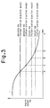
- decision rotational speeds (decision Ne) for starting the cut-off of fuel in the fuel cut-off mode are set respectively in the former-period injection mode and the latter-period injection mode.
- a decision Ne first fuel cut-off lower- limit rotational speed, indicated with a dash-double dot line in the figure
- Decision Ne second fuel cut-off lower-limit rotational speed, indicated with a dot-dash line.
- return rotational speeds (return Ne) for restarting the supply of fuel from the fuel cut-off mode are set respectively in the former- and latter- period injection modes.
- a Return Ne (first return rotational speed, indicated with a dash-double dot line in the figure) in the latter-period injection mode is set lower than a return Ne (second return rotational speed, indicated with a dot-dash line in the figure) in the former-period injection mode.
- the supply of fuel is stopped and the fuel cut-off mode is started.
- the engine speed Ne decreases gradually to the Return Ne (point B) in the former-period injection mode
- the supply of fuel is restarted and the engine speed Ne is maintained at a predetermined rotational speed (idling condition).
- the stop of fuel supply and the start thereof can be performed at a lower engine speed than in the former-period injection mode. Consequently, it becomes possible to effect fuel supply and stop in a wide engine speed range including not only a high speed range but also a low speed range of the engine. Besides, since the supply of fuel is started at a lower rotational speed, the number of times of fuel supply and stop is large, or the fuel supply and stop period becomes longer, whereby fuel economy can be improved without deterioration of combustion.
- the fuel infection mode returns to the same injection mode as to that before change-over to the fuel cut-off mode at the time of starting the supply of fuel from the fuel cut-off mode, no limitation is made thereto.
- the return may be made to the latter-period injection mode or to the former-period injection mode according to the state of operation at the time of starting the supply of fuel from the fuel cut-off mode.
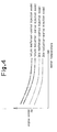
- idling speeds are respectively set in the former-period injection mode and the latter-period injection mode according to water temperatures.
- an Idle Ne first target idling speed, indicated with a thin dash-double dot line in the figure
- Idle Ne second target idling speed, indicated with a thin dot-dash line in the figure
- return rotational speeds (Return Ne) are respectively set in the former- and latter-period injection modes according to water temperatures.
- a Return Ne first return rotational speed, indicated with a thick dash-double dot line in the figure
- a Return Ne second return rotational speed, indicated with a thick dot-dash line in the figure).
- the injection of fuel is performed in the latter-period injection mode, so the Idle Ne in the former-period injection mode is not used.
- a specific operating condition such as a fail safe condition, for example, in the event of decrease in negative pressure of the brake master cylinder, a failure of the throttle position sensor 30, or a cold state of the engine, the injection of fuel is conducted in the former-period injection mode. For this reason, the Idle Ne is set in the former-period injection mode.
- the aforesaid Decision Ne, the Return Ne, and the Idle Ne in the former- and latter-period injection modes are set at respective appropriate rotational speeds according to the type of transmission used, that is, whether the transmission used is a manual transmission or an automatic transmission.
- the respective rotational speeds are set also according to whether an air conditioner, for example, is ON or OFF.
- the Idle Ne in the latter-period injection mode of a vehicle equipped with an automatic transmission is set at a lower rotational speed in the drive range than in the neutral range according to whether an auxiliary device such as an air conditioner is ON or OFF (setting of each rotational speed based on a load member which exerts an influence on the output of the engine and which is driven by the engine output shaft).
- the Decision Ne, the Return Ne, and the Idle Ne in the latter-period injection mode which is superior in both combustion and responsivity, are set on a lower rotational speed side than the Decision Ne, the Return Ne and the Idle Ne in the former-period injection mode. Therefore, during operation in the latter-period injection mode, the fuel cut-off mode, as well as idling, can be carried out at a low engine speed. Consequently, it is possible to improve fuel economy without causing deterioration of combustion.
- the fuel supply is restarted from the fuel cut-off mode for only one or plural cylinders out of all the cylinders prior to decrease of the engine speed down to the Return Ne.
- the Return Ne in the latter-period injection mode can be set at a still lower rotational speed.
- the intra-injection type four-cylinder engine 1 has been described as an example of the internal combustion engine in the above embodiment, the present invention is also applicable to a single cylinder engine or a V-shaped six-cylinder engine.
- control system for internal combustion engine permits improvement of fuel economy without causing deterioration of combustion.
Landscapes
- Engineering & Computer Science (AREA)
- Chemical & Material Sciences (AREA)
- Combustion & Propulsion (AREA)
- Mechanical Engineering (AREA)
- General Engineering & Computer Science (AREA)
- Electrical Control Of Air Or Fuel Supplied To Internal-Combustion Engine (AREA)
- Output Control And Ontrol Of Special Type Engine (AREA)
Priority Applications (1)
| Application Number | Priority Date | Filing Date | Title |
|---|---|---|---|
| EP99106625A EP0926328B1 (fr) | 1996-08-09 | 1997-07-30 | Système de commande pour moteur à combustion interne |
Applications Claiming Priority (3)
| Application Number | Priority Date | Filing Date | Title |
|---|---|---|---|
| JP21080696 | 1996-08-09 | ||
| JP210806/96 | 1996-08-09 | ||
| JP21080696 | 1996-08-09 |
Related Child Applications (1)
| Application Number | Title | Priority Date | Filing Date |
|---|---|---|---|
| EP99106625.9 Division-Into | 1999-03-31 |
Publications (3)
| Publication Number | Publication Date |
|---|---|
| EP0824186A2 true EP0824186A2 (fr) | 1998-02-18 |
| EP0824186A3 EP0824186A3 (fr) | 1999-07-21 |
| EP0824186B1 EP0824186B1 (fr) | 2001-11-21 |
Family
ID=16595451
Family Applications (2)
| Application Number | Title | Priority Date | Filing Date |
|---|---|---|---|
| EP97113156A Expired - Lifetime EP0824186B1 (fr) | 1996-08-09 | 1997-07-30 | Système de commande pour un moteur à combustion interne |
| EP99106625A Expired - Lifetime EP0926328B1 (fr) | 1996-08-09 | 1997-07-30 | Système de commande pour moteur à combustion interne |
Family Applications After (1)
| Application Number | Title | Priority Date | Filing Date |
|---|---|---|---|
| EP99106625A Expired - Lifetime EP0926328B1 (fr) | 1996-08-09 | 1997-07-30 | Système de commande pour moteur à combustion interne |
Country Status (8)
| Country | Link |
|---|---|
| US (1) | US5832893A (fr) |
| EP (2) | EP0824186B1 (fr) |
| KR (1) | KR100233932B1 (fr) |
| CN (1) | CN1082615C (fr) |
| DE (2) | DE69708413T2 (fr) |
| ES (2) | ES2165548T3 (fr) |
| MY (1) | MY120940A (fr) |
| TW (1) | TW353697B (fr) |
Cited By (3)
| Publication number | Priority date | Publication date | Assignee | Title |
|---|---|---|---|---|
| FR2795025A1 (fr) * | 1999-06-18 | 2000-12-22 | Toyota Motor Co Ltd | Appareil de commande de moteur a combustion interne de vehicule |
| EP0997624A3 (fr) * | 1998-10-30 | 2001-02-28 | Mitsubishi Jidosha Kogyo Kabushiki Kaisha | Système de contrôle pour un moteur Diesel |
| EP1081365A3 (fr) * | 1999-08-31 | 2003-06-04 | Toyota Jidosha Kabushiki Kaisha | Procédé et appareil pour le contrôle de l'injection multiple dans un moteur diesel |
Families Citing this family (7)
| Publication number | Priority date | Publication date | Assignee | Title |
|---|---|---|---|---|
| SE522177C2 (sv) * | 1996-08-27 | 2004-01-20 | Mitsubishi Motors Corp | Styranordning för en förbränningsmotor med cylinderinsprutning och gnisttändning |
| US6874467B2 (en) * | 2002-08-07 | 2005-04-05 | Hitachi, Ltd. | Fuel delivery system for an internal combustion engine |
| DE102010028286B4 (de) * | 2010-04-28 | 2021-07-15 | Zf Friedrichshafen Ag | Verfahren zum Betreiben eines Antriebsstrangs |
| JP5707967B2 (ja) * | 2011-01-24 | 2015-04-30 | 日産自動車株式会社 | 内燃機関の過給圧診断装置 |
| EP2696053B1 (fr) * | 2011-04-08 | 2018-01-17 | Toyota Jidosha Kabushiki Kaisha | Dipsositif de commande pour un moteur à combustion interne avec compresseur volumétrique |
| US9790876B2 (en) * | 2013-03-14 | 2017-10-17 | Cummins Ip, Inc. | Advanced exhaust gas recirculation fueling control |
| CN105143650B (zh) * | 2013-04-16 | 2018-06-08 | 株式会社电装 | 能够推断内燃机的温度的内燃机的控制装置 |
Citations (1)
| Publication number | Priority date | Publication date | Assignee | Title |
|---|---|---|---|---|
| JPH05240044A (ja) | 1992-02-28 | 1993-09-17 | Mitsubishi Motors Corp | 筒内噴射型内燃機関 |
Family Cites Families (13)
| Publication number | Priority date | Publication date | Assignee | Title |
|---|---|---|---|---|
| DE2615504C2 (de) * | 1976-04-09 | 1984-09-27 | Franz 7332 Eislingen Semmler | Vorrichtung zur Unterbrechung der Kraftstoffzufuhr zu einem Verbrennungsmotor eines Kraftfahrzeuges bei Schubbetrieb |
| EP0158887B1 (fr) * | 1984-03-31 | 1990-11-22 | Mitsubishi Jidosha Kogyo Kabushiki Kaisha | Système de régénération pour oxydeur à particules pour moteur Diesel |
| JPH0436034A (ja) * | 1990-05-29 | 1992-02-06 | Daihatsu Motor Co Ltd | 減速時の燃料制御方法 |
| JPH0571405A (ja) * | 1991-02-02 | 1993-03-23 | Sanshin Ind Co Ltd | 筒内燃料噴射式2サイクル内燃機関 |
| US5119781A (en) * | 1991-02-28 | 1992-06-09 | General Motors Corporation | Control of engine fuel injection during transitional periods associated with deceleration fuel cut-off |
| JP3182787B2 (ja) * | 1991-06-10 | 2001-07-03 | トヨタ自動車株式会社 | 内燃機関の供給燃料制御装置 |
| JPH04370343A (ja) * | 1991-06-19 | 1992-12-22 | Fuji Heavy Ind Ltd | 2サイクルエンジンのアイドル回転数制御装置 |
| JPH0579370A (ja) * | 1991-09-19 | 1993-03-30 | Toyota Motor Corp | 筒内噴射式内燃機関 |
| US5305720A (en) * | 1992-02-28 | 1994-04-26 | Mitsubishi Jidosha Kogyo Kabushiki Kaisha | Internal combustion engine |
| JPH08232742A (ja) * | 1995-02-28 | 1996-09-10 | Sanshin Ind Co Ltd | 筒内噴射式2サイクルエンジンの運転制御装置 |
| JP2812236B2 (ja) * | 1995-03-10 | 1998-10-22 | トヨタ自動車株式会社 | 圧縮着火式内燃機関 |
| JP3175535B2 (ja) * | 1995-05-16 | 2001-06-11 | 三菱自動車工業株式会社 | 内燃エンジンのアイドル回転数制御装置 |
| US5720254A (en) * | 1995-05-19 | 1998-02-24 | Yamaha Hatsudoki Kabushiki Kaisha | Fuel injection system for engine |
-
1997
- 1997-07-30 ES ES97113156T patent/ES2165548T3/es not_active Expired - Lifetime
- 1997-07-30 EP EP97113156A patent/EP0824186B1/fr not_active Expired - Lifetime
- 1997-07-30 EP EP99106625A patent/EP0926328B1/fr not_active Expired - Lifetime
- 1997-07-30 ES ES99106625T patent/ES2187091T3/es not_active Expired - Lifetime
- 1997-07-30 DE DE69708413T patent/DE69708413T2/de not_active Expired - Fee Related
- 1997-07-30 DE DE69718330T patent/DE69718330T2/de not_active Expired - Fee Related
- 1997-08-05 US US08/905,951 patent/US5832893A/en not_active Expired - Fee Related
- 1997-08-07 TW TW086111312A patent/TW353697B/zh active
- 1997-08-07 MY MYPI97003610A patent/MY120940A/en unknown
- 1997-08-08 CN CN97117324A patent/CN1082615C/zh not_active Expired - Fee Related
- 1997-08-09 KR KR1019970038090A patent/KR100233932B1/ko not_active Expired - Fee Related
Patent Citations (1)
| Publication number | Priority date | Publication date | Assignee | Title |
|---|---|---|---|---|
| JPH05240044A (ja) | 1992-02-28 | 1993-09-17 | Mitsubishi Motors Corp | 筒内噴射型内燃機関 |
Cited By (3)
| Publication number | Priority date | Publication date | Assignee | Title |
|---|---|---|---|---|
| EP0997624A3 (fr) * | 1998-10-30 | 2001-02-28 | Mitsubishi Jidosha Kogyo Kabushiki Kaisha | Système de contrôle pour un moteur Diesel |
| FR2795025A1 (fr) * | 1999-06-18 | 2000-12-22 | Toyota Motor Co Ltd | Appareil de commande de moteur a combustion interne de vehicule |
| EP1081365A3 (fr) * | 1999-08-31 | 2003-06-04 | Toyota Jidosha Kabushiki Kaisha | Procédé et appareil pour le contrôle de l'injection multiple dans un moteur diesel |
Also Published As
| Publication number | Publication date |
|---|---|
| DE69718330D1 (de) | 2003-02-13 |
| ES2165548T3 (es) | 2002-03-16 |
| DE69708413T2 (de) | 2003-01-16 |
| KR19980018552A (ko) | 1998-06-05 |
| ES2187091T3 (es) | 2003-05-16 |
| EP0926328A3 (fr) | 2000-07-19 |
| KR100233932B1 (ko) | 1999-12-15 |
| CN1188848A (zh) | 1998-07-29 |
| TW353697B (en) | 1999-03-01 |
| EP0824186A3 (fr) | 1999-07-21 |
| US5832893A (en) | 1998-11-10 |
| EP0926328B1 (fr) | 2003-01-08 |
| EP0926328A2 (fr) | 1999-06-30 |
| EP0824186B1 (fr) | 2001-11-21 |
| MY120940A (en) | 2005-12-30 |
| CN1082615C (zh) | 2002-04-10 |
| DE69718330T2 (de) | 2003-10-23 |
| DE69708413D1 (de) | 2002-01-03 |
Similar Documents
| Publication | Publication Date | Title |
|---|---|---|
| US5722363A (en) | Cylinder-injection type internal combustion engine and a fuel injection control apparatus therefor | |
| US7415955B2 (en) | Starting system for internal combustion engine | |
| KR100236146B1 (ko) | 내연기관의 제어장치 | |
| JP3186598B2 (ja) | 内燃エンジンの制御装置 | |
| US5832893A (en) | Control system for internal combustion engine | |
| JP5504869B2 (ja) | 車両の制御装置 | |
| JP6380675B2 (ja) | 内燃エンジンの燃料噴射制御装置及び制御方法 | |
| JPH09280149A (ja) | 筒内噴射型火花点火式内燃機関の点火時期制御装置 | |
| US5870992A (en) | Combustion control device for internal combustion engine | |
| JP4020582B2 (ja) | 内燃機関の制御装置 | |
| EP1342900A2 (fr) | Commande d'arrêt du fonctionnement d'un moteur à combustion interne | |
| JP2012136980A (ja) | エンジン回転停止制御装置 | |
| JP3289653B2 (ja) | 内燃機関の制御装置 | |
| JP4208994B2 (ja) | 内燃機関 | |
| JP3755308B2 (ja) | 筒内噴射型内燃エンジンの制御装置 | |
| JP3757998B2 (ja) | 筒内噴射型内燃エンジンの制御装置 | |
| JPH08158912A (ja) | エンジンの回転数制御装置 | |
| JP3763206B2 (ja) | 内燃機関 | |
| JPH1054273A (ja) | 内燃機関の制御装置 | |
| JP2017106326A (ja) | ブローバイガス還流制御装置 | |
| JPH11343906A (ja) | 内燃機関 | |
| JPH02104927A (ja) | 内燃エンジンの燃料供給制御方法 | |
| JPH0979079A (ja) | 筒内噴射型火花点火式内燃機関 | |
| JPH11324772A (ja) | 内燃機関 | |
| JPH1077891A (ja) | 内燃エンジンの制御装置 |
Legal Events
| Date | Code | Title | Description |
|---|---|---|---|
| PUAI | Public reference made under article 153(3) epc to a published international application that has entered the european phase |
Free format text: ORIGINAL CODE: 0009012 |
|
| AK | Designated contracting states |
Kind code of ref document: A2 Designated state(s): DE ES FR GB IT SE |
|
| AX | Request for extension of the european patent |
Free format text: AL;LT;LV;RO;SI |
|
| PUAL | Search report despatched |
Free format text: ORIGINAL CODE: 0009013 |
|
| AK | Designated contracting states |
Kind code of ref document: A3 Designated state(s): AT BE CH DE DK ES FI FR GB GR IE IT LI LU MC NL PT SE |
|
| AX | Request for extension of the european patent |
Free format text: AL;LT;LV;RO;SI |
|
| 17P | Request for examination filed |
Effective date: 19991229 |
|
| AKX | Designation fees paid |
Free format text: DE ES FR GB IT SE |
|
| GRAG | Despatch of communication of intention to grant |
Free format text: ORIGINAL CODE: EPIDOS AGRA |
|
| 17Q | First examination report despatched |
Effective date: 20010302 |
|
| GRAG | Despatch of communication of intention to grant |
Free format text: ORIGINAL CODE: EPIDOS AGRA |
|
| GRAG | Despatch of communication of intention to grant |
Free format text: ORIGINAL CODE: EPIDOS AGRA |
|
| GRAH | Despatch of communication of intention to grant a patent |
Free format text: ORIGINAL CODE: EPIDOS IGRA |
|
| RIN1 | Information on inventor provided before grant (corrected) |
Inventor name: TAMURA, HIROKI Inventor name: NOMURA, TOSHIRO Inventor name: HATAYAMA, KENJIRO Inventor name: KAMURA, HITOSHI |
|
| GRAH | Despatch of communication of intention to grant a patent |
Free format text: ORIGINAL CODE: EPIDOS IGRA |
|
| GRAA | (expected) grant |
Free format text: ORIGINAL CODE: 0009210 |
|
| AK | Designated contracting states |
Kind code of ref document: B1 Designated state(s): DE ES FR GB IT SE |
|
| REG | Reference to a national code |
Ref country code: GB Ref legal event code: IF02 |
|
| REF | Corresponds to: |
Ref document number: 69708413 Country of ref document: DE Date of ref document: 20020103 |
|
| REG | Reference to a national code |
Ref country code: ES Ref legal event code: FG2A Ref document number: 2165548 Country of ref document: ES Kind code of ref document: T3 |
|
| ET | Fr: translation filed | ||
| PLBE | No opposition filed within time limit |
Free format text: ORIGINAL CODE: 0009261 |
|
| STAA | Information on the status of an ep patent application or granted ep patent |
Free format text: STATUS: NO OPPOSITION FILED WITHIN TIME LIMIT |
|
| 26N | No opposition filed | ||
| REG | Reference to a national code |
Ref country code: FR Ref legal event code: CA |
|
| PGFP | Annual fee paid to national office [announced via postgrant information from national office to epo] |
Ref country code: FR Payment date: 20060719 Year of fee payment: 10 |
|
| PGFP | Annual fee paid to national office [announced via postgrant information from national office to epo] |
Ref country code: ES Payment date: 20060724 Year of fee payment: 10 |
|
| PGFP | Annual fee paid to national office [announced via postgrant information from national office to epo] |
Ref country code: GB Payment date: 20060726 Year of fee payment: 10 |
|
| PGFP | Annual fee paid to national office [announced via postgrant information from national office to epo] |
Ref country code: DE Payment date: 20060727 Year of fee payment: 10 |
|
| PGFP | Annual fee paid to national office [announced via postgrant information from national office to epo] |
Ref country code: IT Payment date: 20060731 Year of fee payment: 10 |
|
| PGFP | Annual fee paid to national office [announced via postgrant information from national office to epo] |
Ref country code: SE Payment date: 20060705 Year of fee payment: 10 |
|
| EUG | Se: european patent has lapsed | ||
| GBPC | Gb: european patent ceased through non-payment of renewal fee |
Effective date: 20070730 |
|
| PG25 | Lapsed in a contracting state [announced via postgrant information from national office to epo] |
Ref country code: SE Free format text: LAPSE BECAUSE OF NON-PAYMENT OF DUE FEES Effective date: 20070731 Ref country code: DE Free format text: LAPSE BECAUSE OF NON-PAYMENT OF DUE FEES Effective date: 20080201 |
|
| PG25 | Lapsed in a contracting state [announced via postgrant information from national office to epo] |
Ref country code: GB Free format text: LAPSE BECAUSE OF NON-PAYMENT OF DUE FEES Effective date: 20070730 |
|
| REG | Reference to a national code |
Ref country code: FR Ref legal event code: ST Effective date: 20080331 |
|
| PG25 | Lapsed in a contracting state [announced via postgrant information from national office to epo] |
Ref country code: FR Free format text: LAPSE BECAUSE OF NON-PAYMENT OF DUE FEES Effective date: 20070731 |
|
| REG | Reference to a national code |
Ref country code: ES Ref legal event code: FD2A Effective date: 20070731 |
|
| PG25 | Lapsed in a contracting state [announced via postgrant information from national office to epo] |
Ref country code: ES Free format text: LAPSE BECAUSE OF NON-PAYMENT OF DUE FEES Effective date: 20070731 |
|
| PG25 | Lapsed in a contracting state [announced via postgrant information from national office to epo] |
Ref country code: IT Free format text: LAPSE BECAUSE OF NON-PAYMENT OF DUE FEES Effective date: 20070730 |