EP0826825B1 - Dispositif d'enduction pour appliquer de façon directe ou indirecte une sauce de couchage liquide ou pâteuse sur une bande en mouvement, particulièrement papier ou carton - Google Patents
Dispositif d'enduction pour appliquer de façon directe ou indirecte une sauce de couchage liquide ou pâteuse sur une bande en mouvement, particulièrement papier ou carton Download PDFInfo
- Publication number
- EP0826825B1 EP0826825B1 EP97109916A EP97109916A EP0826825B1 EP 0826825 B1 EP0826825 B1 EP 0826825B1 EP 97109916 A EP97109916 A EP 97109916A EP 97109916 A EP97109916 A EP 97109916A EP 0826825 B1 EP0826825 B1 EP 0826825B1
- Authority
- EP
- European Patent Office
- Prior art keywords
- application
- material web
- coating
- moving web
- limiting device
- Prior art date
- Legal status (The legal status is an assumption and is not a legal conclusion. Google has not performed a legal analysis and makes no representation as to the accuracy of the status listed.)
- Expired - Lifetime
Links
- 239000011248 coating agent Substances 0.000 title claims description 42
- 238000000576 coating method Methods 0.000 title claims description 42
- 235000011837 pasties Nutrition 0.000 title claims description 17
- 239000012530 fluid Substances 0.000 title 1
- 239000007788 liquid Substances 0.000 claims description 14
- 238000000034 method Methods 0.000 claims description 9
- 230000003534 oscillatory effect Effects 0.000 claims 3
- 238000012544 monitoring process Methods 0.000 claims 1
- 239000000463 material Substances 0.000 description 51
- 230000007704 transition Effects 0.000 description 7
- 239000011111 cardboard Substances 0.000 description 6
- 239000011087 paperboard Substances 0.000 description 5
- 238000010586 diagram Methods 0.000 description 4
- 230000001105 regulatory effect Effects 0.000 description 4
- 239000000047 product Substances 0.000 description 3
- 230000009467 reduction Effects 0.000 description 3
- 238000005096 rolling process Methods 0.000 description 3
- 230000000694 effects Effects 0.000 description 2
- 238000009413 insulation Methods 0.000 description 2
- 230000007246 mechanism Effects 0.000 description 2
- 230000010355 oscillation Effects 0.000 description 2
- 230000008569 process Effects 0.000 description 2
- 238000007789 sealing Methods 0.000 description 2
- 230000009471 action Effects 0.000 description 1
- 230000005540 biological transmission Effects 0.000 description 1
- 239000007795 chemical reaction product Substances 0.000 description 1
- 239000012141 concentrate Substances 0.000 description 1
- 230000004069 differentiation Effects 0.000 description 1
- 238000005470 impregnation Methods 0.000 description 1
- 238000012423 maintenance Methods 0.000 description 1
- 239000002184 metal Substances 0.000 description 1
- 239000000123 paper Substances 0.000 description 1
- 230000000737 periodic effect Effects 0.000 description 1
- 239000004753 textile Substances 0.000 description 1
Images


Classifications
-
- B—PERFORMING OPERATIONS; TRANSPORTING
- B05—SPRAYING OR ATOMISING IN GENERAL; APPLYING FLUENT MATERIALS TO SURFACES, IN GENERAL
- B05C—APPARATUS FOR APPLYING FLUENT MATERIALS TO SURFACES, IN GENERAL
- B05C5/00—Apparatus in which liquid or other fluent material is projected, poured or allowed to flow on to the surface of the work
- B05C5/02—Apparatus in which liquid or other fluent material is projected, poured or allowed to flow on to the surface of the work the liquid or other fluent material being discharged through an outlet orifice by pressure, e.g. from an outlet device in contact or almost in contact, with the work
- B05C5/0254—Coating heads with slot-shaped outlet
- B05C5/0266—Coating heads with slot-shaped outlet adjustable in length, e.g. for coating webs of different width
-
- D—TEXTILES; PAPER
- D21—PAPER-MAKING; PRODUCTION OF CELLULOSE
- D21H—PULP COMPOSITIONS; PREPARATION THEREOF NOT COVERED BY SUBCLASSES D21C OR D21D; IMPREGNATING OR COATING OF PAPER; TREATMENT OF FINISHED PAPER NOT COVERED BY CLASS B31 OR SUBCLASS D21G; PAPER NOT OTHERWISE PROVIDED FOR
- D21H23/00—Processes or apparatus for adding material to the pulp or to the paper
- D21H23/02—Processes or apparatus for adding material to the pulp or to the paper characterised by the manner in which substances are added
- D21H23/22—Addition to the formed paper
- D21H23/32—Addition to the formed paper by contacting paper with an excess of material, e.g. from a reservoir or in a manner necessitating removal of applied excess material from the paper
-
- B—PERFORMING OPERATIONS; TRANSPORTING
- B05—SPRAYING OR ATOMISING IN GENERAL; APPLYING FLUENT MATERIALS TO SURFACES, IN GENERAL
- B05C—APPARATUS FOR APPLYING FLUENT MATERIALS TO SURFACES, IN GENERAL
- B05C11/00—Component parts, details or accessories not specifically provided for in groups B05C1/00 - B05C9/00
- B05C11/02—Apparatus for spreading or distributing liquids or other fluent materials already applied to a surface ; Controlling means therefor; Control of the thickness of a coating by spreading or distributing liquids or other fluent materials already applied to the coated surface
- B05C11/04—Apparatus for spreading or distributing liquids or other fluent materials already applied to a surface ; Controlling means therefor; Control of the thickness of a coating by spreading or distributing liquids or other fluent materials already applied to the coated surface with blades
Definitions
- the present invention relates to a commissioned work for direct or indirect application of a liquid or pasty coating medium on a running material web, in particular made of paper or cardboard, according to the preamble of claim 1.
- the invention further relates to a Procedure for the direct or indirect application of a liquid or pasty coating medium on a running Material web, in particular made of paper or cardboard, according to the Preamble of claim 4.
- Coating lines used to make a running web of material for example made of paper, cardboard or a textile material exists, on one or both sides with one or more Layers of the coating medium, for example color, thickness, Impregnation liquid or the like.
- the liquid or pasty coating medium directly from an application device applied to the surface of the running material web, that during the order on a rotating counter surface, for example an endless belt or a counter-roller, is supported.
- a support surface e.g. the surface of one as an applicator roller designed counter roll, applied to from there in one Nip through which the material web runs from the application roller to be transferred to the material web.
- Generic custom works are from the DE-C-4425137, DE-A-3438181 US-A-4860 686 and US-A-5,435,847 include an application roller or a counter roller on which at direct application one with a liquid or pasty Material to be coated runs, one of the Opposing roller opposite application device for application of the coating medium, and one of the application device downstream and over the entire machine width extending doctor element, for example a doctor blade, scrapes off the excess coating medium applied.
- these commissioned works also comprise at least one adjustable streak border device for Setting the stroke width on a job or Counter roller or the running material web.
- the application unit according to DE-A-4425137 has as Application device one between a storage wall and d ⁇ m Squeegee element formed coating chamber, the side is sealed by sealing blocks.
- Stroke delimiter will be the two Associated side edges of the running material web Format sheets used, each in one with one respective sealing block connected format sheet holder held are.
- a streak border element thus formed is by means of a slide element transverse to the direction of the Slidable material web for setting the coating format and remains during the ongoing operation of the application in the position once set.
- the application mechanism according to DE-C-3438181 is essentially similar to that according to DE-C-4425137 in contrast, however, as a delimitation device Stroke boundary elements that are separate from the lateral insulation blocks or insulation boards of the Coating chamber provided and relative to the counter roller are adjustable and lockable. With these The delimitation elements are more precise So-called edge scrapers, which are analogous to the format plates of the DE-C-4425137 during operation of the applicator remain in the position once set.
- the application unit according to US Pat. No. 5,435,847 also corresponds to essentially those according to DE-A-3438181 and DE-C-4425137, however, it has two as a delimiter Format sliders, each one side of the current Material web are assigned and one between two opposite walls formed laterally close.
- a respective format slider is for Setting the line width on the running material web in a direction transverse to the running material web Slidable and fixable in the gap and remains during the ongoing operation of the commissioning plant in the once set position.
- FIG. 3 shows a schematic plan view of an application unit according to the prior art in the area of the doctor element and the edge of the material web, the doctor element, here: a doctor blade 14, being folded into the material web plane for better illustration.
- the areas of the material web 6 coated with the pasty coating medium 4 are shown in dotted lines in FIG. 3.
- the doctor element 14 is generally no longer usable for use with a format setting that has changed compared to the original setting, ie a changed stroke width B g , since the wear point 24 now leads to an undesirable irregularity of the stroke and a reduction in quality of the finished product can lead, so that the doctor element 14 usually has to be exchanged for another. If the transition point between the coated B g and the uncoated edge area B R is not on the applicator or counter roller 2 but on the material web 4 itself, the resulting abrupt difference in thickness of the material web 4, ie the thickness difference between the coated B g and uncoated B R material web section, moreover, not inconsiderable problems occur when rolling up, unrolling or rewinding the material web 4.
- the present invention is therefore based on the object a simple and effective generic application as well as a suitable method for direct or indirect Apply a liquid or pasty medium to a running material web, in particular made of paper or cardboard, to create the state of the art mentioned above technical problems as far as possible avoids and producing a high quality End product.
- the delimitation device comprises at least two delimitation elements, namely for each edge of the material web or the order and / or Counter roll of the applicator one, it being these Elements such as sheet metal, scrapers or Format slider is.
- Format sliders can, for example, in the metering gap of a free jet nozzle Application device are arranged and the metering gap to the Complete page margins, one at a time Format slide parallel to the length of the metering gap is moving gradually or continuously.
- the coating edge limiting device possible.
- the application mechanism according to the invention allows for simple and effective way a significant reduction and Uniformization of local wear or Grinding effect of the doctor element at the transition points between the painted and uncoated margin and thus an increase in the service life of the doctor element.
- This enables longer compared to the known prior art Maintenance intervals until the required replacement of the Doctor element, which in turn longer downtimes of Avoided and lower total cost of ownership be achieved. Since in the application according to the invention no pronounced local wear on the Doctor element occurs, this is for one versus one Original setting changed format setting, i.e. Line width, usable without having to replace the Doctor element is necessary or a reduction in quality manufactured product occurs.
- the Stroke limiting device drives during application and or if necessary moved to adjust the stroke width during the application.
- the drive device it is generally at least one any device, manually or mechanically driven, such as at least one electronic, pneumatic, hydraulic, magnetic, electromagnetic actuator or a corresponding motor, etc., or mixed forms thereof.
- the drive device can depend on Embodiment of course suitable gear means, Transmission elements, connecting elements and the like exhibit.
- the streak limiter as above already mentioned, usually at least two delimitation elements includes, namely on each edge of the Material web or application and / or counter roll is one expediently each streak border delimitation element has its own Drive device assigned. Of course there is also one common drive device conceivable.
- Control and / or regulating device includes.
- About the Control and / or regulating device can be simple and Not only an automatic setting of the deleted format width made for example also the exact form of movement of the gradual, steady or also oscillating movement of the coating edge limiting device predetermined and / or controlled and / or per se changing operating conditions are adapted.
- the above object is further achieved by a Method according to the invention with the features of the claim 4.
- the inventive method for direct or indirect application of a liquid or pasty Coating medium on a running material web, in particular made of paper or cardboard, by means of an application that at least one adjustable streak border limiting device for setting the line width on a job or Includes counter roll and / or the running material web, is characterized by gradual or continuous and / or oscillating movement of the coating edge limiting device in an essentially transverse to the current Material web lying direction.
- the specialist For the oscillating movements of the coating border establishment, of course, with a steady or Step movement can be superimposed, the specialist a variety of waveforms are available, such as harmonic, anharmonic, periodic or aperiodic Vibrations.
- the amplitude and / or the Wavelength of the oscillating movement during operation vary. Even the movement can be carried out at intervals, i.e. the Stroke limiting device stops for a certain, Time span (if necessary a longer time span) a first setting is essentially constant and changes then slowly or quickly to a second shot, the then again essentially for a period of time is kept constant.
- the step size be constant or vary.
- FIG. 1 A schematic bottom view of FIG. 1 shows a preferred embodiment of the application unit according to the invention designed for direct application.
- the applicator comprises a counter roller 2 with the width B w , on which a material web 6 to be provided with an application, ie with a liquid or pasty coating medium 4, runs, which is supported by the counter roller 2 during the application process.
- the material web has the width B M.
- the pasty coating medium 4 and the areas coated with the pasty coating medium 4 are shown in dotted lines in the drawing.
- the running direction of the material web 6 is indicated in the figure by an arrow.
- the free jet nozzle of the application device A is formed by a metering gap 12 delimited by two lips 8, 10.
- the application unit A is followed in the direction of travel of the material web 4 by a doctor element which extends over the entire width of the machine, here a doctor blade 14, and doctor the excess applied coating medium 4 onto a suitable profile.
- the applicator further comprises an adjustable coating edge limiting device 16, 18 assigned to the applicator device A, which closes the metering gap 12 on its two side edges and thus specifies a certain line width of the application 4 on the counter roller 2 and the material web 6 running on it.
- the coating edge delimitation device comprises two coating edge delimitation elements, hereinafter referred to as format sliders 16, 18, wherein a format slider 16, 18 is assigned to a side edge of the running material web 6. As shown in the drawing, the format slides 16, 18 are each movably positioned within a lateral edge area of the metering gap 12.
- the movable arrangement of a respective format slide 16, 18 is in this case such that the format slide 16, 18 is easy to move both for setting the line width B g parallel to the longitudinal extent of the metering gap 12, that is to say transversely to the running material web 6, and also oscillating for manipulation of the coating edge is.
- the oscillating mobility of the format slide 16, 18 is indicated in the figure by a double arrow and the simple displaceability by two separate, opposite arrows from the opposite direction.
- a respective format slide 16, 18 is coupled via suitable connecting means to a drive device, in the present case an electrical actuator 20, and can be moved by the latter in the manner described above.
- the actuators 20 of both format slides 16, 18 are integrated in a control circuit R and a control circuit S of a common control / regulating device 22, by means of which an operator has an average line width B gM for a given web width B M or a given width B w of the counter roller 2 and can specify the exact movement of the format slider 16, 18 if necessary.
- the two format sliders 1, 18 in the ongoing operation of the application by means of Actuators 20 in a lying towards the center of the machine Moving direction.
- the format slides lead 16, 18 in the said direction but a slow one harmonic vibration with an amplitude of about 10 mm.
- the average stroke width B gM is selected in the present case so that an uncoated edge 6.2 remains free on the material web 6.
- the movement of the format slides results in a wavy edge profile 4.2 (which clearly shows the harmonic movement of the format slides 16, 18) of the applied liquid or pasty coating medium 4 without an abrupt transition between a painted and an uncoated area 6.2.
- the respective local width of the uncoated edge 6.2 also varies, for which, similarly to the line width, an average edge width B RM is expediently to be defined.
- the wave-shaped edge course 4.2 is then blurred by the action of the doctor blade 14 to form a uniform uncoated edge 6.4 of essentially constant width B R , without the technical problems inherent in the prior art being related occur on the pronounced local wear of the doctor blade 14.
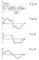
- FIGS. 2a-e show schematic diagrams of various Forms of movement or oscillation of the Wiping device, i.e. of each Format slider 16, 18 of the application unit according to the invention, where the abscissa of each diagram represents the time axis and the ordinate represents the amplitude axis.
- the shown Movement or vibration forms are exclusive exemplary nature. The invention is self-evident not fixated on these forms of vibration.
- the Movements of the individual format sliders 16, 18 can the others generally take place in phase or out of phase, as indicated in Fig. 2a by the dashed curve.
- the waveforms of the individual Format sliders 16, 18 of the same type or of one another to be different.
- Figure 2e is an oscillating Basic movement form of the respective format slides 16, 18 recognizably overlaid with a gradual movement.
- the Diagrams are also self-explanatory, so that there is no need for further explanations.
- the application unit according to the invention can rather also others as the configurations described above.
- the transition area between the painted and uncoated margin not mandatory as in the above embodiment on the material web itself lie, but can also over the edge of the web go out and concentrate partially or exclusively on the Counter roll.
- the exact shape of the oscillating Movement of the delimitation device can basically any suitable form of vibration assume, in particular, the amplitude and / or The wavelength and / or frequency of the vibration vary. Of another is fundamentally different Scraper border device than that described above conceivable; as well as other suitable drive devices for the delimiter.
- the invention is not absolutely necessary that the Stroke delimiter one by the Drive device forced oscillating movement executes; the streak border limiting device can also be used be excited to natural vibrations in a suitable manner.
Landscapes
- Coating Apparatus (AREA)
- Application Of Or Painting With Fluid Materials (AREA)
- Paper (AREA)
Claims (4)
- Dispositif d'enduction pour appliquer de façon directe ou indirecte une sauce de couchage liquide ou pâteuse (4) sur une bande de matière en mouvement (6), en particulier en papier ou en carton, comprenant au moins un dispositif de limitation latérale du couchage (16, 18) réglable pour le réglage d'une largeur du tracé sur un rouleau d'application ou un rouleau antagoniste (2) et/ou la bande de matière en mouvement (6), caractérisé en ce que le dispositif de limitation latérale du couchage (16, 18) est disposé de façon mobile pas à pas ou en continu dans une direction orientée sensiblement transversalement à la bande de matière en mouvement (6) et en ce qu'il est prévu au moins un dispositif d'entraínement (20) relié au dispositif de limitation latérale du couchage (16, 18), qui entraíne le dispositif de limitation latérale du couchage (16, 18) pas à pas, en continu et/ou en mouvement oscillant pendant l'application et/ou en cas de besoin le déplace pour le réglage de la largeur du tracé (BgM) pendant l'application.
- Dispositif d'enduction suivant la revendication 1, caractérisé en ce que celui-ci comprend au moins un dispositif de contrôle et/ou de régulation (22) connecté au dispositif d'entraínement (20).
- Procédé pour appliquer de façon directe ou indirecte une sauce de couchage liquide ou pâteuse (4) sur une bande de matière en mouvement (6), en particulier en papier ou en carton, au moyen d'un dispositif d'enduction, qui comprend au moins un dispositif de limitation latérale du couchage (16, 18) réglable pour le réglage de la largeur du tracé sur un rouleau d'application ou un rouleau antagoniste (2) et/ou la bande de matière en mouvement (6), caractérisé par la mise en mouvement pas à pas ou en continu et/ou par oscillation du dispositif de limitation latérale du couchage (16, 18) dans une direction orientée sensiblement transversalement à la bande de matière en mouvement (6).
- Procédé suivant la revendication 3, caractérisé en ce que le mouvement oscillant est effectué avec une amplitude d'environ 10 mm.
Applications Claiming Priority (2)
| Application Number | Priority Date | Filing Date | Title |
|---|---|---|---|
| DE19631888 | 1996-08-07 | ||
| DE19631888A DE19631888A1 (de) | 1996-08-07 | 1996-08-07 | Auftragwerk zum direkten oder indirekten Auftragen eines flüssigen oder pastösen Streichmediums auf eine laufende Materialbahn, insbesondere aus Papier oder Karton |
Publications (3)
| Publication Number | Publication Date |
|---|---|
| EP0826825A2 EP0826825A2 (fr) | 1998-03-04 |
| EP0826825A3 EP0826825A3 (fr) | 1999-06-16 |
| EP0826825B1 true EP0826825B1 (fr) | 2001-09-12 |
Family
ID=7802040
Family Applications (1)
| Application Number | Title | Priority Date | Filing Date |
|---|---|---|---|
| EP97109916A Expired - Lifetime EP0826825B1 (fr) | 1996-08-07 | 1997-06-18 | Dispositif d'enduction pour appliquer de façon directe ou indirecte une sauce de couchage liquide ou pâteuse sur une bande en mouvement, particulièrement papier ou carton |
Country Status (5)
| Country | Link |
|---|---|
| US (1) | US5893951A (fr) |
| EP (1) | EP0826825B1 (fr) |
| JP (1) | JPH1066917A (fr) |
| BR (1) | BR9702730A (fr) |
| DE (2) | DE19631888A1 (fr) |
Families Citing this family (13)
| Publication number | Priority date | Publication date | Assignee | Title |
|---|---|---|---|---|
| US6423144B1 (en) * | 1996-08-07 | 2002-07-23 | Matsushita Electric Industrial Co., Ltd. | Coating apparatus and coating method |
| WO1999034932A1 (fr) * | 1998-01-09 | 1999-07-15 | Fastar, Ltd. | Appareil et procede d'enduction, a tete mobile |
| DE19807000A1 (de) * | 1998-02-19 | 1999-08-26 | Voith Sulzer Papiertech Patent | Vorrichtung und Verfahren zum Auftragen eines flüssigen oder pastösen Auftragsmediums auf einen Auftragsbereich eines laufenden Untergrunds |
| DE19830728C2 (de) * | 1998-07-09 | 2001-08-02 | Reinhard Duespohl Maschb Gmbh | Kleber-Auftragsvorrichtung |
| WO2001068982A1 (fr) * | 2000-03-14 | 2001-09-20 | Voith Paper Patent Gmbh | Dispositif d'application |
| DE20216794U1 (de) * | 2002-10-30 | 2004-03-11 | Nordson Corporation, Westlake | Vorrichtung zum Auftragen von Fluid |
| DE10331325A1 (de) * | 2003-07-10 | 2005-02-03 | Voith Paper Patent Gmbh | Auftragsvorrichtung mit verstellbarer Auftragsbreite |
| EP1614483A3 (fr) * | 2004-07-05 | 2006-11-15 | Jakob Weiss & Sohne Maschinenfabrik Gmbh | Dispositif et procédé de raclage |
| JP4902983B2 (ja) * | 2005-11-01 | 2012-03-21 | ボイス ペ−パ− パテント ゲ−エムベ−ハ− | 塗工装置および塗工方法 |
| JP4902984B2 (ja) * | 2005-11-01 | 2012-03-21 | ボイス ペ−パ− パテント ゲ−エムベ−ハ− | 塗工装置および塗工方法 |
| JP5491250B2 (ja) * | 2010-03-26 | 2014-05-14 | 富士フイルム株式会社 | エクストルージョン塗布装置及び塗布フィルムの製造方法 |
| CN104437975B (zh) * | 2013-09-22 | 2017-04-26 | 宸美(厦门)光电有限公司 | 涂布装置以及涂布方法 |
| CN109663705B (zh) * | 2019-01-28 | 2023-08-15 | 昆山鸣朋纸业有限公司 | 一种瓦楞纸上胶机及上胶工艺 |
Family Cites Families (13)
| Publication number | Priority date | Publication date | Assignee | Title |
|---|---|---|---|---|
| DE3438181A1 (de) * | 1984-10-18 | 1986-04-24 | J.M. Voith Gmbh, 7920 Heidenheim | Randabdichtung fuer streicheinrichtung zur beschichtung laufender warenbahnen |
| DE3513063A1 (de) * | 1985-04-12 | 1986-10-16 | Jagenberg AG, 4000 Düsseldorf | Streicheinrichtung zur beschichtung von entlang einer gegenwalze gefuehrten warenbahn, insbesondere papierbahnen |
| DE3621417C1 (en) * | 1986-06-26 | 1987-08-06 | Flachglas Ag | Doctor device |
| US4860686A (en) * | 1986-11-26 | 1989-08-29 | Beloit Corporation | Coating width regulating apparatus |
| DE3908386A1 (de) * | 1989-03-15 | 1990-09-27 | Jagenberg Ag | Verfahren und vorrichtung zum beschichten von materialbahnen, insbesondere von papier- oder kartonbahnen |
| DE3919087A1 (de) * | 1989-06-10 | 1990-12-13 | Voith Gmbh J M | Streicheinrichtung |
| FI91025C (fi) * | 1991-02-08 | 1995-08-22 | Valmet Paper Machinery Inc | Menetelmä paperin tai muun rainamateriaalin päällystemäärän poikkiprofiilin säätämiseksi ja menetelmän toteuttamiseen tarkoitettu päällystysasema |
| DE4120487A1 (de) * | 1991-06-21 | 1992-12-24 | E M Mueller Kg | Linearantrieb fuer bewegungsablaeufe |
| KR100272064B1 (ko) * | 1992-10-27 | 2000-12-01 | 미우라 아끼라 | 다이 도장기 |
| DE4341341C1 (de) * | 1993-12-06 | 1995-03-09 | Jagenberg Ag | Dosiersystem für Vorrichtungen zum Beschichten von Materialbahnen, insbesondere Papier- oder Kartonbahnen |
| DE4425137C1 (de) * | 1994-07-15 | 1995-09-14 | Feldmuehle Ag Stora | Streichrandbegrenzer für eine Kurzverweilzeit-Streicheinrichtung |
| DE19500402A1 (de) * | 1995-01-09 | 1996-07-11 | Agfa Gevaert Ag | Vorhanggießer |
| DE29613687U1 (de) * | 1996-08-07 | 1996-10-24 | Voith Sulzer Papiermaschinen GmbH, 89522 Heidenheim | Auftragwerk zum direkten oder indirekten Auftragen eines flüssigen oder pastösen Streichmediums auf eine laufende Materialbahn, insbesondere aus Papier oder Karton |
-
1996
- 1996-08-07 DE DE19631888A patent/DE19631888A1/de not_active Withdrawn
-
1997
- 1997-06-18 DE DE59704587T patent/DE59704587D1/de not_active Expired - Lifetime
- 1997-06-18 EP EP97109916A patent/EP0826825B1/fr not_active Expired - Lifetime
- 1997-08-05 JP JP9210338A patent/JPH1066917A/ja active Pending
- 1997-08-06 US US08/905,275 patent/US5893951A/en not_active Expired - Lifetime
- 1997-08-07 BR BR9702730A patent/BR9702730A/pt not_active Application Discontinuation
Also Published As
| Publication number | Publication date |
|---|---|
| EP0826825A3 (fr) | 1999-06-16 |
| JPH1066917A (ja) | 1998-03-10 |
| EP0826825A2 (fr) | 1998-03-04 |
| DE19631888A1 (de) | 1998-02-12 |
| US5893951A (en) | 1999-04-13 |
| DE59704587D1 (de) | 2001-10-18 |
| BR9702730A (pt) | 1998-11-10 |
Similar Documents
| Publication | Publication Date | Title |
|---|---|---|
| EP0826825B1 (fr) | Dispositif d'enduction pour appliquer de façon directe ou indirecte une sauce de couchage liquide ou pâteuse sur une bande en mouvement, particulièrement papier ou carton | |
| DE2203482C3 (de) | Verfahren und Vorrichtung zum Beschichten einerMaterialbahn mit Bestrechmasse durch wenigstens zwei in Förderrichtung der Bahn in Abstand voneinander angeordnete Bestreichorgane | |
| DE69128243T2 (de) | Anpressdrucksteuerung der Schaberklingenlängskante für eine Rakeleinrichtung | |
| EP1219747B1 (fr) | Procédé et appareil pour nettoyer une bande de transport | |
| EP0147536A2 (fr) | Appareil pour étendre régulièrement un écoulement liquide sur une largeur donnée | |
| EP0826824B1 (fr) | Dispositif d'enduction pour appliquer de façon directe ou indirecte une sauce de couchage liquide ou pâteuse sur une bande en mouvement, particulièrement papier ou carton | |
| DE4242582C2 (de) | Rakelanordnung | |
| EP0761877A2 (fr) | Dispositif d'application directe ou indirecte de matériau fluide ou pâteux sur une bande en mouvement, en particulier de papier ou carton | |
| DE3927329A1 (de) | Vorrichtung zum beschichten einer um eine gegenwalze gefuehrten materialbahn | |
| DE19722117C2 (de) | Beschichtung poröser Träger | |
| DE19652289A1 (de) | Vorrichtung zum direkten oder indirekten Auftragen eines flüssigen oder pastösen Mediums auf eine laufende Materialbahn, insbesondere aus Papier oder Karton | |
| DE29622365U1 (de) | Auftragswerk zum direkten oder indirekten Auftragen eines flüssigen oder pastösen Mediums auf eine laufende Materialbahn | |
| EP0402589A2 (fr) | Appareil de revêtement | |
| DE69321433T2 (de) | Beschichtungsvorrichtung mit gegenläufigen rollen | |
| EP0108887A2 (fr) | Installation d'enduction | |
| EP0855464A2 (fr) | Dispositif et méthode d'enduction directe ou indirecte d'une substance liquide ou pâteuse ssur une bande en mouvement | |
| EP1531043A1 (fr) | Procédé et dispositif pour déplacer une racle | |
| DE19631913A1 (de) | Auftragwerk zum direkten oder indirekten einseitigen oder beidseitigen Auftragen eines flüssigen oder pastösen Mediums auf eine laufende Materialbahn, insbesondere aus Papier oder Karton | |
| DE69620464T2 (de) | Klingenhalterung | |
| DE3938052A1 (de) | Verfahren zur kompensation der durchbiegung einer schaberklinge und durchbiegungskompensierte schaberklinge | |
| DE19532920A1 (de) | Auftragswerk zum direkten oder indirekten Auftragen eines flüssigen oder pastösen Mediums auf eine laufende Materialbahn | |
| EP0821102B1 (fr) | Dispositif pour l'application directe d'une substance fluide ou pâteuse sur une bande en mouvement, particulièrement de papier ou carton | |
| EP0808668A2 (fr) | Dispositif d'application pour l'application directe ou indirecte d'un liquide ou d'une pâte sur une bande en défilement | |
| DE2931800A1 (de) | Beschichtungsvorrichtung | |
| DE19604934A1 (de) | Auftragsystem für eine Vorrichtung zum Beschichten einer Papier- oder Kartonbahn |
Legal Events
| Date | Code | Title | Description |
|---|---|---|---|
| PUAI | Public reference made under article 153(3) epc to a published international application that has entered the european phase |
Free format text: ORIGINAL CODE: 0009012 |
|
| AK | Designated contracting states |
Kind code of ref document: A2 Designated state(s): DE FI FR GB IT SE |
|
| PUAL | Search report despatched |
Free format text: ORIGINAL CODE: 0009013 |
|
| AK | Designated contracting states |
Kind code of ref document: A3 Designated state(s): DE FI FR GB IT SE |
|
| RIC1 | Information provided on ipc code assigned before grant |
Free format text: 6D 21H 23/32 A, 6B 05C 5/00 B, 6B 05C 5/02 B, 6B 05C 11/04 B, 6B 05D 7/00 B, 6D 21H 23:78 Z |
|
| RAP1 | Party data changed (applicant data changed or rights of an application transferred) |
Owner name: VOITH SULZER PAPIERTECHNIK PATENT GMBH |
|
| 17P | Request for examination filed |
Effective date: 19991216 |
|
| AKX | Designation fees paid |
Free format text: DE FI FR GB IT SE |
|
| RAP1 | Party data changed (applicant data changed or rights of an application transferred) |
Owner name: VOITH PAPER PATENT GMBH |
|
| GRAG | Despatch of communication of intention to grant |
Free format text: ORIGINAL CODE: EPIDOS AGRA |
|
| GRAG | Despatch of communication of intention to grant |
Free format text: ORIGINAL CODE: EPIDOS AGRA |
|
| GRAH | Despatch of communication of intention to grant a patent |
Free format text: ORIGINAL CODE: EPIDOS IGRA |
|
| 17Q | First examination report despatched |
Effective date: 20010220 |
|
| GRAH | Despatch of communication of intention to grant a patent |
Free format text: ORIGINAL CODE: EPIDOS IGRA |
|
| GRAA | (expected) grant |
Free format text: ORIGINAL CODE: 0009210 |
|
| AK | Designated contracting states |
Kind code of ref document: B1 Designated state(s): DE FI FR GB IT SE |
|
| PG25 | Lapsed in a contracting state [announced via postgrant information from national office to epo] |
Ref country code: GB Free format text: LAPSE BECAUSE OF FAILURE TO SUBMIT A TRANSLATION OF THE DESCRIPTION OR TO PAY THE FEE WITHIN THE PRESCRIBED TIME-LIMIT Effective date: 20010912 |
|
| REF | Corresponds to: |
Ref document number: 59704587 Country of ref document: DE Date of ref document: 20011018 |
|
| ET | Fr: translation filed | ||
| GBV | Gb: ep patent (uk) treated as always having been void in accordance with gb section 77(7)/1977 [no translation filed] |
Effective date: 20010912 |
|
| PLBE | No opposition filed within time limit |
Free format text: ORIGINAL CODE: 0009261 |
|
| STAA | Information on the status of an ep patent application or granted ep patent |
Free format text: STATUS: NO OPPOSITION FILED WITHIN TIME LIMIT |
|
| 26N | No opposition filed | ||
| PGFP | Annual fee paid to national office [announced via postgrant information from national office to epo] |
Ref country code: FR Payment date: 20030618 Year of fee payment: 7 |
|
| PG25 | Lapsed in a contracting state [announced via postgrant information from national office to epo] |
Ref country code: FR Free format text: LAPSE BECAUSE OF NON-PAYMENT OF DUE FEES Effective date: 20050228 |
|
| REG | Reference to a national code |
Ref country code: FR Ref legal event code: ST |
|
| PG25 | Lapsed in a contracting state [announced via postgrant information from national office to epo] |
Ref country code: IT Free format text: LAPSE BECAUSE OF NON-PAYMENT OF DUE FEES;WARNING: LAPSES OF ITALIAN PATENTS WITH EFFECTIVE DATE BEFORE 2007 MAY HAVE OCCURRED AT ANY TIME BEFORE 2007. THE CORRECT EFFECTIVE DATE MAY BE DIFFERENT FROM THE ONE RECORDED. Effective date: 20050618 |
|
| PGFP | Annual fee paid to national office [announced via postgrant information from national office to epo] |
Ref country code: SE Payment date: 20110613 Year of fee payment: 15 |
|
| PGFP | Annual fee paid to national office [announced via postgrant information from national office to epo] |
Ref country code: FI Payment date: 20110613 Year of fee payment: 15 |
|
| PGFP | Annual fee paid to national office [announced via postgrant information from national office to epo] |
Ref country code: DE Payment date: 20110622 Year of fee payment: 15 |
|
| REG | Reference to a national code |
Ref country code: SE Ref legal event code: EUG |
|
| PG25 | Lapsed in a contracting state [announced via postgrant information from national office to epo] |
Ref country code: FI Free format text: LAPSE BECAUSE OF NON-PAYMENT OF DUE FEES Effective date: 20120618 |
|
| PG25 | Lapsed in a contracting state [announced via postgrant information from national office to epo] |
Ref country code: SE Free format text: LAPSE BECAUSE OF NON-PAYMENT OF DUE FEES Effective date: 20120619 |
|
| REG | Reference to a national code |
Ref country code: DE Ref legal event code: R119 Ref document number: 59704587 Country of ref document: DE Effective date: 20130101 |
|
| PG25 | Lapsed in a contracting state [announced via postgrant information from national office to epo] |
Ref country code: DE Free format text: LAPSE BECAUSE OF NON-PAYMENT OF DUE FEES Effective date: 20130101 |