EP0828089A2 - Schwingungsisolierende Einrichtung - Google Patents
Schwingungsisolierende Einrichtung Download PDFInfo
- Publication number
- EP0828089A2 EP0828089A2 EP97306883A EP97306883A EP0828089A2 EP 0828089 A2 EP0828089 A2 EP 0828089A2 EP 97306883 A EP97306883 A EP 97306883A EP 97306883 A EP97306883 A EP 97306883A EP 0828089 A2 EP0828089 A2 EP 0828089A2
- Authority
- EP
- European Patent Office
- Prior art keywords
- mounting member
- vibration isolating
- isolating apparatus
- bracket
- liquid chamber
- Prior art date
- Legal status (The legal status is an assumption and is not a legal conclusion. Google has not performed a legal analysis and makes no representation as to the accuracy of the status listed.)
- Granted
Links
Images




Classifications
-
- F—MECHANICAL ENGINEERING; LIGHTING; HEATING; WEAPONS; BLASTING
- F16—ENGINEERING ELEMENTS AND UNITS; GENERAL MEASURES FOR PRODUCING AND MAINTAINING EFFECTIVE FUNCTIONING OF MACHINES OR INSTALLATIONS; THERMAL INSULATION IN GENERAL
- F16F—SPRINGS; SHOCK-ABSORBERS; MEANS FOR DAMPING VIBRATION
- F16F13/00—Units comprising springs of the non-fluid type as well as vibration-dampers, shock-absorbers, or fluid springs
- F16F13/04—Units comprising springs of the non-fluid type as well as vibration-dampers, shock-absorbers, or fluid springs comprising both a plastics spring and a damper, e.g. a friction damper
- F16F13/06—Units comprising springs of the non-fluid type as well as vibration-dampers, shock-absorbers, or fluid springs comprising both a plastics spring and a damper, e.g. a friction damper the damper being a fluid damper, e.g. the plastics spring not forming a part of the wall of the fluid chamber of the damper
- F16F13/08—Units comprising springs of the non-fluid type as well as vibration-dampers, shock-absorbers, or fluid springs comprising both a plastics spring and a damper, e.g. a friction damper the damper being a fluid damper, e.g. the plastics spring not forming a part of the wall of the fluid chamber of the damper the plastics spring forming at least a part of the wall of the fluid chamber of the damper
- F16F13/10—Units comprising springs of the non-fluid type as well as vibration-dampers, shock-absorbers, or fluid springs comprising both a plastics spring and a damper, e.g. a friction damper the damper being a fluid damper, e.g. the plastics spring not forming a part of the wall of the fluid chamber of the damper the plastics spring forming at least a part of the wall of the fluid chamber of the damper the wall being at least in part formed by a flexible membrane or the like
Definitions
- the present invention relates to a vibration isolating apparatus which used to prevent transmission of vibrations from a vibration generating portion, the apparatus being applicable to a mount for supporting a member such as an engine or the like which generates vibrations.
- a vibration isolating apparatus serving as an engine mount is disposed between an engine, which is a vibration generating portion of a vehicle, and a vehicle body, which is a vibration receiving portion of the vehicle. Vibrations generated by the engine are absorbed by the vibration isolating apparatus and are prevented from being transmitted to the vehicle body.
- a structure in which an elastic body and a pair of liquid chambers are provided within the vibration isolating apparatus and a restricted passage serving as an orifice communicates these liquid chambers is known as such a vibration isolating apparatus.
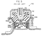
- an elastic body 118 made of rubber is disposed between and adhered by vulcanization to an outer cylindrical metal fitting 120 and an upper mounting metal fitting 116. Further, the outer cylindrical metal fitting 120 is inserted into a bracket 114, and a rebound stopper metal fitting 112 is caulked to the bracket 114.
- a liquid chamber 124 is provided between a diaphragm 122 disposed within the outer cylindrical metal fitting 120 and the elastic body 118.
- a separating wall member 130 which has an orifice 132 and separates the liquid chamber 124 into a pair of liquid chambers 124A and 124B, is disposed within the liquid chamber 124.
- the liquid within both the liquid chambers 124A and 124B flows through the orifice 132 communicating the liquid chambers 124A and 124B with each other, so as to reduce the vibration.
- the lower portion 120B of the outer cylindrical metal fitting 120 shown in Fig. 7 is inclined toward an inner peripheral side as shown by the two-dot chain lines due to the effects of the upper portion 120A of the outer cylindrical metal fitting 120, so that the lower portion 120B is not smoothly deformed. Accordingly, the separating wall member 130 is unstable within the outer cylindrical metal fitting 120 such that the sealing between the pair of liquid chambers 124A and 124B by the separating wall member 130 may be insufficient and the sealing of the liquid chamber 124 itself may be insufficient such that there is a risk that the liquid within the liquid chamber 124 may leak to the exterior thereof.
- the vibration isolating apparatus is being assembled by the above method, since the position of the separating wall member 130 is restricted only by a step 118A of the elastic body 118 which is elastic and flexible, the separating wall member 130 is moved in the vertical direction in the drawing or the separating wall member 130 rides onto the elastic body 118. As a result, it is difficult to stably seal the pair of liquid chambers 124A and 124B by the separating wall member 130.
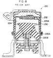
- a vibration isolating apparatus 210 (see Fig. 8) is provided which is structured such that a pair of outer cylindrical metal fittings 220A and 220B are employed as the outer cylindrical metal fitting, and a separating wall member 230 having an orifice 232 is caulked between the pair of outer cylindrical metal fittings 220A and 220B so as to be disposed within a liquid chamber 224.
- a sealing portion 230A of the separating wall member 230 is disposed at the outer peripheral side of the vibration isolating apparatus 210 and is sealed by caulking, the caulked portion projects toward the outer peripheral side of the vibration isolating apparatus 210.
- the present invention has been achieved by taking the above facts into consideration, and a first object of the present invention is to provide a vibration isolating apparatus in which stable sealing by a separating wall member is achieved, and a second object of the present invention is to provide a vibration isolating apparatus in which there is no caulked portion projecting toward an outer peripheral side such that the vibration isolating apparatus can be made compact in the radial direction.
- a vibration isolating apparatus comprising:
- the elastic body is disposed between the first mounting member and the second mounting member.
- the liquid chamber containing the liquid in a sealed manner is formed by an inner wall which is at least partly formed by the elastic body.
- the separating wall member which is disposed within the liquid chamber and separates the liquid chamber into the pair of small liquid chambers, includes the orifice which communicates the pair of small liquid chambers with each other.
- the second mounting member is press fitted into the bracket, and the pair of mounting members and the elastic body are housed within the bracket.
- the elastic body when vibrations are transmitted from the vibration generating portion which is connected, for example, to the first mounting member, the elastic body is deformed. Together with this deformation, the liquid chamber expands and contacts such that the pressure of the liquid within the orifice of the separating wall member changes and the liquid flows. The vibrations are damped by the deformation of the elastic body, the pressure change of the liquid, and the flow of the liquid. Therefore, it is difficult for the vibrations to be transmitted to the vibration receiving portion.
- the vibration isolating apparatus includes the engaging portion which projects toward the inner peripheral side at an axial direction substantially intermediate position of the second mounting member which is formed in a cylindrical shape. Accordingly, the outer peripheral side of the separating wall member is engaged with the engaging portion so as to position the separating wall member in the axial direction.
- the separating wall member can thereby be stably positioned within the liquid chamber and can reliably seal between the pair of small chambers. Further, since the separating wall member is disposed at the inner side of the vibration isolating apparatus and dose not project outwardly of the second mounting member, the vibration isolating apparatus can be made compact in the radial direction.
- the sealing between the pair of small liquid chambers by the separating wall members can be achieved by drawing the outer diameter of the second mounting member.
- the engaging portion which projects toward the inner peripheral side is provided at the second mounting member between the axial direction end sides thereof.
- only the distal end side i.e., the leading end side in the direction of inserting the second mounting member into the bracket
- drawing processing together with the extension of the engaging portion, only the distal end side is deformed and does not give effect the base end side. Therefore, the distal end side is easily deformed independently of the base end side which is the portion of the second mounting member which is not drawn. Accordingly, subjecting the second mounting member to drawing processing is easy, and the diameter of the seal portion can be substantially uniformly reduced along the axial direction.
- the pair of portions of the second mounting member between which, in the axial direction of the second mounting member, the engaging portion is disposed are the distal end side (leaking end side) in the direction of press fitting the second mounting member into the bracket and the base end side.
- the distal end side is formed so as to have a smaller diameter than that of the base end side.
- Fig. 1 is a partial cross sectional view which shows an embodiment of a vibration isolating apparatus in accordance with the present invention.
- Fig. 2 is a side view which shows the embodiment of the vibration isolating apparatus in accordance with the present invention.
- Fig. 3 is another side view which shows the embodiment of the vibration isolating apparatus in accordance with the present invention.
- Fig. 4 is a cross sectional view for explaining assembly of the embodiment of a vibration isolating apparatus in accordance with the present invention.
- Fig. 5 is a cross sectional view which shows a first conventional vibration isolating apparatus.
- Fig. 6 is a side view which shows the first conventional vibration isolating apparatus.
- Fig. 7 is a cross sectional view which shows an outer cylindrical metal fitting of the first conventional vibration isolating apparatus.
- Fig. 8 is a cross sectional view which shows a second conventional vibration isolating apparatus.
- FIG. 1 to 4 An embodiment of a vibration isolating apparatus in accordance with the present invention will be shown in Figs. 1 to 4 and will be explained below with reference to these drawings.
- one of the mounting members of a vibration isolating apparatus 10 is an outer cylindrical metal fitting 16 formed by a cylindrical thin metal material.
- the outer cylindrical metal fitting 16 includes a first cylindrical portion 16B formed in a cylindrical shape, and a second cylindrical portion 16C formed in a cylindrical shape at the lower side of the first cylindrical portion 16B and having an outer diameter slightly smaller than an outer diameter of the first cylindrical portion 16B.
- An engaging portion 16E which projects toward an inner peripheral side and is formed by depressing the outer peripheral surface of the outer cylindrical metal fitting 16 along the periphery thereof by a press forming or the like, is provided at an intermediate position in the axial direction between the first cylindrical portion 16B and the second cylindrical portion 16C of the outer cylindrical metal fitting 16. Further, a circular-plate-shaped flange portion 16A is formed at the upper end portion of the outer cylindrical metal fitting 16. A taper portion 16D, which is compressed in a taper shape, is formed at the lower end portion of the outer cylindrical metal fitting 16.
- the outer cylindrical metal fitting 16 is press fitted to a bracket 12, which is formed in a cup shape, so as to be disposed within the bracket 12.
- a flange portion 12A expanding toward an outer periphery is formed at the upper portion of the bracket 12.
- An upper side portion of the bracket 12 opposing the first cylindrical portion 16B of the outer cylindrical metal fitting 16 is an upper portion cylindrical portion 12B which is closely fit with the first cylindrical portion 16B.
- a lower side portion of the bracket 12 opposing the second cylindrical portion 16C of the outer cylindrical metal fitting 16 is a lower portion cylindrical portion 12C which is formed so as to have a diameter slightly smaller than that of the upper portion cylindrical portion 12B. There is a slight gap (not shown) between the lower portion cylindrical portion 12C and the second cylindrical portion 16C.
- a pair of leg portions 14 each formed in a U-shape is provided at the outer peripheral side of the bracket 12 in such a manner as to project toward the outer peripheral side of the bracket 12, as shown in Figs. 2 and 3.
- a portion of the elastic body 18 corresponding to the second cylindrical portion 16C of the outer cylindrical metal fitting 16 is a thin portion 18A having a thin thickness.
- An upper portion mounting member 24 made of metal and formed in a conical shape is embedded in a central portion of the elastic body 18 and adhered thereto by vulcanization. An upper end portion of the upper portion mounting member 24 projects from the elastic body 18.
- a screw hole 24A having a female screw is provided in the upper portion mounting member 24, and a rotation prevention pin 25 is attached to the upper portion mounting member 24.
- the elastic member 18 is disposed and mounted between the upper portion mounting member 24 which is a first mounting member and the outer cylindrical metal fitting 16 which is a second mounting member.
- the outer cylindrical metal fitting 16, the upper portion mounting member 24 and the elastic body 18 are housed in the bracket 12 by press fitting the first cylindrical portion 16B of the outer cylindrical metal fitting 16 into the upper portion cylindrical portion 12B of the bracket 12.
- An arm bracket 26 is provided at a position at the upper side of the upper portion mounting member 24 and opposing the top surface of the upper portion mounting member 24 via a stopper rubber 22.
- a square pillar portion 26A which is a base end side of the arm bracket 26 and is formed by iron casting or the like, is press fitted into the cylindrical stopper rubber 22, such that the arm bracket 26 is disposed via the stopper rubber 22.
- a hole 22A is formed in the top wall of the stopper rubber 22, an opening 22B is formed in the bottom wall of the stopper rubber 22, and a through hole 27A is formed in the square pillar portion 26A.
- a fastening bolt 28 is inserted from above into the hole 22A formed in the top wall of the stopper rubber 22, the through hole 27A formed in the square pillar portion 26A and the opening 22B formed in the bottom wall of the stopper rubber 22. Together with this insertion, the fastening bolt 28 is screwed into the screw hole 24A of the upper portion mounting member 24 so that the arm bracket 26 is fixed to the upper portion mounting member 24.
- a plurality of bolt holes 27B for connecting the arm bracket 26 to an engine (not shown), which serves as a vibration generating portion, are formed in the distal end side of the arm bracket 26. Accordingly, the upper portion mounting member 24 projecting from the elastic body 18 is used for connection to the engine such that the upper portion mounting member 24 is connected to the engine, which is the vibration generating portion, via the arm bracket 26.
- a rebound stopper metal fitting 60 for limiting displacement of the upper portion mounting member 24 to a certain range is disposed at the top portion of the upper portion mounting member 24 via the arm bracket 26 in such a manner as to oppose to the upper portion mounting member 24.
- the end portions of the rebound stopper metal fitting 60 having an inverse U-shaped configuration are press fitted into the pair of leg portions 14.
- Through holes 14A and 60A are formed in the leg portions 14 and the both end portions of the rebound stopper metal fitting 60, respectively.
- a pair of fastening screws 64 shown in Fig. 3 pass through the through holes 14A of the leg portions 14 and the through holes 60A of the rebound stopper metal fitting 60 and are fastened to a vehicle body 62 serving as a vibration receiving portion so that the vibration isolating apparatus 10 is fixed to the vehicle body 62.
- a ring member 31 is fit within and fixed to the second cylindrical portion 16C.
- a rubber diaphragm 30 is adhered by vulcanization to the inner peripheral surface of the ring member 31.
- a liquid chamber 32 whose inner peripheral walls are formed by the diaphragm 30 and the elastic body 18, is provided between the diaphragm 30 and the elastic body 18.
- a liquid such as water, oil or the like is housed within the liquid chamber 32 in a sealed manner.
- a separating wall member 34 formed by, for example, a synthetic resin material, is fitted with the inner wall surface of the thin portion 18A of the elastic body 18 and an outer peripheral side thereof is engaged with the engaging portion 16E so as to be positioned in the axial direction.
- the separating wall member 34 separates the liquid chamber 32 into a pair of small liquid chambers, that is, a main liquid chamber 32A and a sub liquid chamber 32B.
- a circular opening 38 is formed in a central portion of the separating wall member 34.
- a groove portion 36 is provided in the outer peripheral end portion 34B which is an outer peripheral surface of the separating wall member 34.
- the groove portion 36 is formed in a groove shape along substantially the entire periphery of the outer peripheral end portion 34B.
- a small hole 52 communicating the main liquid chamber 32A with the inside of the groove portion 36 is formed in an end portion of the groove portion 36.
- a small hole 54 for communicating the sub liquid chamber 32B with the inside of the groove portion 36 is formed in the other end portion of the groove portion 36. Accordingly, the groove portion 36 and the small holes 52 and 54, which are closed by the inner wall surface of the elastic body 18, form an orifice 42 for communication between the main liquid chamber 32A and the sub liquid chamber 32B.
- a space between the diaphragm 30 and the bottom wall of the bracket 12 is an air chamber 44,which makes it possible for the diaphragm 30 to deform.
- a rib 34A projecting toward an inner peripheral side is formed at a portion of the separating wall member 34 near the upper portion of the opening 38.
- a membrane 46 which is an elastic plate having a circularly projecting central portion is anchored by the rib 34A.
- a metal circular plate 48 which has a central portion which circularly projects so as to be fitted into the opening 38, abuts a lower side outer peripheral portion of the membrane 46 such that the membrane 46 is held by the circular plate 48 and the rib 34A.
- the outer peripheral end side of the circular plate 48 is held between the diaphragm 30 and the separating wall member 34 so as to be fixed between them, and has the illustrated hole portion at a position of the circular plate 48 corresponding to the small hole 54.
- the outer cylindrical metal fitting 16 having the first cylindrical portion 16A, the second cylindrical portion 16C, the engaging portion 16E and the like is formed by press forming.
- the upper portion mounting member 24 and the outer cylindrical metal fitting 16 are placed in a metal mold, and the elastic body 18 is vulcanized.
- the separating wall member 34, the diaphragm 30 and the like, to which the membrane 46 and the circular plate 48 are attached are inserted into the outer cylindrical metal fitting 16.
- the separating wall member 34 is axially positioned by the outer peripheral side of the separating wall member 34 engaging with the engaging portion 16E of the outer cylindrical metal fitting 16
- the second cylindrical portion 16C of the outer cylindrical metal fitting 16 is drawn and the lower end portion of the outer cylindrical metal fitting 16 is caulked so as to form the taper portion 16D.
- the thin portion 18A of the elastic body 18 and the ring member 31 are closely brought into contact with each other and fitted together so as to seal the liquid chamber 32. Further, the thin portion 18A and the separating wall member 34 are closely brought into contact with each other and fitted together such that the separating wall member 34 seals between the pair of liquid chambers 32A and 32B, which is the state shown in Fig. 4. As a result, the separating wall member 34 is held between the engaging portion 16E and the taper portion 16D.
- the square pillar portion 26A of the arm bracket 26 is press fitted into the stopper rubber 22.
- the fastening bolt 28 is inserted through the stopper rubber 22 and the arm bracket 26 so that the arm bracket 26 is fixed to the upper portion mounting member 24.
- the outer cylindrical metal fitting 16 is press fitted into the bracket 12, and the upper portion mounting member 24, the outer cylindrical metal fitting 16 and the elastic body 18 are housed in the bracket 12. Together with this operation, the both end portions of the rebound stopper metal fitting 60 are press fitted into the pair of leg portions 14, which are formed so as to project from the bracket 12, so that the rebound stopper metal fitting 60 is provisionally anchored to the pair of leg portions 14.
- the assembly of the vibration isolating apparatus 10 is completed as shown in Figs. 1 and 2.
- the outer cylindrical metal fitting 16 is inserted into the bracket 12.
- the second cylindrical portion 16C of the outer cylindrical metal fitting 16 has a diameter slightly smaller than that of the lower portion cylindrical portion 12C of the bracket 12, the outer cylindrical metal fitting 16 is smoothly inserted until midway through the insertion thereof.
- the first cylindrical portion 16B of the outer cylindrical metal fitting 16 and the upper portion cylindrical portion 12B of the bracket 12 are press fitted so as to be closely fitted to one another, and are thereby fixed to one another.
- the vibration isolating apparatus 10 which is completed in the above-described manner is set in a vehicle, and the pair of fastening screws 64 are inserted through the pair of leg portions 14 and the both end portions of the rebound stopper metal fitting 60, thereby fastening the fastening screws 64 to the vehicle body 62.
- the bracket 12, which is connected to the pair of leg portions 14, and the rebound stopper metal fitting 60 are fixed to the vehicle body 62 so that the vibration isolating apparatus 10 can be mounted to the vehicle body 62.
- bolts (not shown) are fastened with the plurality of bolt holes 27B of the arm bracket 26 so that the arm bracket 26 is connected to the engine.
- the elastic body 18 functions as a vibration absorbing main body, and can absorb vibrations by a vibration damping function which is based on the internal friction of the elastic body 18. Further, the liquid within the main liquid chamber 32A and the sub liquid chamber 32B flows back and forth between the chambers through the orifice 42 so that the vibration isolating effect can be improved by the damping operation which is based on the change in the pressure of the liquid which change is generated in the orifice space, the viscous resistance of the liquid flow, and the like.
- the membrane 46 is elastically deformed so that the internal pressure within the liquid chamber 32 does not become high.
- the apparatus becomes a low frequency moving spring so that the vibration isolating characteristic is not reduced but is maintained, such that the effects of the vibration isolating apparatus 10 are sufficiently exhibited.
- the rebound stopper metal fitting 60 which is disposed so as to oppose the outer cylindrical metal fitting 16, limits displacement of the outer cylindrical metal fitting 16 to a certain range.
- the outer cylindrical metal fitting 16 is press fitted into the bracket 12, and the outer cylindrical metal fitting 16, the upper portion mounting member 24 and the elastic body 18 are housed in the bracket 12.
- the outer cylindrical metal fitting 16 has, at the substantially central portion thereof in the axial direction, the engaging portion 16E projecting toward the inner peripheral side. Accordingly, the outer peripheral side of the separating wall member 34 is engaged with the engaging portion 16E and the separating wall member 34 is positioned, in the axial direction, within the liquid chamber 32, so that the set position of the separating wall member 34 within the liquid chamber 32 is stabilized and the separating wall member 34 reliably seals between the pair of liquid chambers 32A and 32B. Since the separating wall member 34 is disposed in the inside of the vibration isolating apparatus 10 and does not projected out of the outer cylindrical metal fitting 16, the vibration isolating apparatus 10 can be made compact in the radial direction thereof.
- sealing between the liquid chambers 32A and 32B by the separating wall member 34 is achieved by drawing the second cylindrical portion 16C of the outer cylindrical metal fitting 16.
- the engaging portion 16E which projects toward the inner peripheral side, at the outer cylindrical metal fitting 16
- draw only the second cylindrical portion 16C which is one of the axial direction portions of the outer cylindrical metal fitting 16 and between the first cylindrical portion 16B and which the engaging portion 16E is provided. Accordingly, the drawing process of the outer cylindrical metal fitting 16 is easily performed so that the diameter of the seal portion can be substantially uniformly reduced in the axial direction. Therefore, there is no insufficient sealing between the liquid chambers by the separating wall member and no insufficient sealing of the liquid chamber with respect to the exterior, as have occurred in the conventional art.
- the engaging portion 16E of the outer cylindrical metal fitting 16 is disposed between, along the axial direction of the outer cylindrical metal fitting 16, the second cylindrical portion 16C, which is the leading (distal) end side in the direction of press fitting the outer cylindrical metal fitting 16 into the bracket 12, and the first cylindrical portion 16B, which is the base end side in the direction of fitting the outer cylindrical metal fitting 16 into the bracket.
- the diameter of the second cylindrical portion 16C is smaller than that of the first cylindrical portion 16B.
- the above embodiment is structured such that the upper portion mounting member 24 which is the first mounting member is connected to the engine which is the vibration generating portion and the bracket 12 is connected to the vehicle body 62 which to the vibration receiving portion.
- the upper portion mounting member 24 may be connected to the vibration receiving portion
- the bracket 12 may be connected to the vibration generating portion.
- the engaging portion 16E is formed around the outer peripheral surface of the outer cylindrical metal fitting 16.
- a plurality of engaging portions may be formed along the peripheral direction of the outer cylindrical metal fitting 16.
- the vibration isolating apparatus is used to isolate the vibrations of an engine which is installed in a vehicle.
- the vibration isolating apparatus in accordance with the present invention can also be applied to a body mount for a vehicle or the like, or to other structures unrelated to vehicles.
- the shape and the size of the elastic body and the like and the number of orifices are not limited to those used in the present embodiment.
- the vibration isolating apparatus in accordance with the present invention can prevent the separating wall member from shifting within the liquid chamber so that stable sealing is achieved by the separating wall member, and no caulked portion projecting toward an outer peripheral side is provided so that the vibration isolating apparatus can be made compact in the radial direction thereof.
Landscapes
- Engineering & Computer Science (AREA)
- General Engineering & Computer Science (AREA)
- Mechanical Engineering (AREA)
- Combined Devices Of Dampers And Springs (AREA)
- Arrangement Or Mounting Of Propulsion Units For Vehicles (AREA)
Applications Claiming Priority (3)
| Application Number | Priority Date | Filing Date | Title |
|---|---|---|---|
| JP23901896 | 1996-09-10 | ||
| JP239018/96 | 1996-09-10 | ||
| JP23901896A JP4054079B2 (ja) | 1996-09-10 | 1996-09-10 | 防振装置 |
Publications (3)
| Publication Number | Publication Date |
|---|---|
| EP0828089A2 true EP0828089A2 (de) | 1998-03-11 |
| EP0828089A3 EP0828089A3 (de) | 2000-12-20 |
| EP0828089B1 EP0828089B1 (de) | 2002-08-14 |
Family
ID=17038677
Family Applications (1)
| Application Number | Title | Priority Date | Filing Date |
|---|---|---|---|
| EP97306883A Expired - Lifetime EP0828089B1 (de) | 1996-09-10 | 1997-09-04 | Schwingungsisolierende Einrichtung |
Country Status (4)
| Country | Link |
|---|---|
| US (1) | US5964456A (de) |
| EP (1) | EP0828089B1 (de) |
| JP (1) | JP4054079B2 (de) |
| DE (1) | DE69714673T2 (de) |
Cited By (1)
| Publication number | Priority date | Publication date | Assignee | Title |
|---|---|---|---|---|
| CN102792050A (zh) * | 2010-01-12 | 2012-11-21 | 株式会社普利司通 | 隔振装置 |
Families Citing this family (30)
| Publication number | Priority date | Publication date | Assignee | Title |
|---|---|---|---|---|
| JP3438561B2 (ja) * | 1997-12-26 | 2003-08-18 | 東海ゴム工業株式会社 | 液体封入式防振装置 |
| JP3603651B2 (ja) * | 1999-03-09 | 2004-12-22 | 東海ゴム工業株式会社 | 流体封入式防振装置の製造方法 |
| JP3489500B2 (ja) | 1999-08-10 | 2004-01-19 | 東海ゴム工業株式会社 | 防振装置 |
| JP3767403B2 (ja) | 2001-03-30 | 2006-04-19 | 東海ゴム工業株式会社 | 流体封入式防振装置 |
| JP3666484B2 (ja) * | 2001-06-21 | 2005-06-29 | 東洋ゴム工業株式会社 | 液封入式防振装置 |
| JP4187137B2 (ja) * | 2001-09-07 | 2008-11-26 | 東洋ゴム工業株式会社 | 液封入式防振装置 |
| JP3901070B2 (ja) * | 2001-10-26 | 2007-04-04 | 東海ゴム工業株式会社 | 液体封入式防振装置 |
| KR100489110B1 (ko) * | 2002-03-25 | 2005-05-12 | 현대자동차주식회사 | 자동차의 엔진 마운팅 구조 |
| US20040188901A1 (en) * | 2003-03-31 | 2004-09-30 | Cooper Technology Service, Llc | Engine mount |
| US20070182076A1 (en) * | 2003-08-06 | 2007-08-09 | Freudenberg-Nok General Partner | Vibration isolator with reflective external travel restrictor and compressive snubber |
| US7055811B2 (en) * | 2004-05-03 | 2006-06-06 | Toyo Tire And Rubber Co., Ltd. | Vibration isolating device |
| JP4277316B2 (ja) * | 2005-03-30 | 2009-06-10 | 東海ゴム工業株式会社 | 防振装置 |
| JP5085107B2 (ja) * | 2006-11-28 | 2012-11-28 | 株式会社ブリヂストン | エンジンマウント構造 |
| US7341244B1 (en) * | 2007-02-26 | 2008-03-11 | Paulstra Crc | Hydraulic antivibration support |
| JP5264255B2 (ja) * | 2008-04-04 | 2013-08-14 | 株式会社ブリヂストン | 防振装置 |
| WO2011145656A1 (ja) * | 2010-05-19 | 2011-11-24 | 山下ゴム株式会社 | 液封防振装置 |
| JP5689709B2 (ja) * | 2011-02-18 | 2015-03-25 | 株式会社ブリヂストン | 防振装置、及び、防振装置用ブラケット |
| KR101315771B1 (ko) * | 2011-12-09 | 2013-10-10 | 현대자동차주식회사 | 차량용 엔진 마운트 |
| US9541155B2 (en) | 2013-08-09 | 2017-01-10 | Sumitomo Riko Company Limited | Mounting member for vibration damping device and vibration damping device using the same |
| WO2015145672A1 (ja) * | 2014-03-27 | 2015-10-01 | 住友理工株式会社 | 防振装置 |
| JP6388787B2 (ja) * | 2014-04-28 | 2018-09-12 | 株式会社ブリヂストン | 弾性ストッパ部材及び防振装置 |
| DE102014118502B4 (de) | 2014-12-12 | 2018-09-06 | Vibracoustic Gmbh | Lageranordnung zum Lagern eines Motors |
| JP6393200B2 (ja) * | 2015-01-23 | 2018-09-19 | 山下ゴム株式会社 | 防振装置および緩衝装置 |
| WO2018062165A1 (ja) * | 2016-09-27 | 2018-04-05 | 株式会社ブリヂストン | 防振装置 |
| JP6456340B2 (ja) * | 2016-11-17 | 2019-01-23 | 東洋ゴム工業株式会社 | 防振装置 |
| JP6456339B2 (ja) | 2016-11-17 | 2019-01-23 | 東洋ゴム工業株式会社 | 防振装置 |
| JP6456341B2 (ja) | 2016-11-17 | 2019-01-23 | 東洋ゴム工業株式会社 | 防振装置 |
| JP6807257B2 (ja) * | 2017-03-16 | 2021-01-06 | 住友理工株式会社 | 防振装置 |
| JP7460501B2 (ja) | 2020-10-08 | 2024-04-02 | 株式会社プロスパイラ | 防振装置 |
| US12338871B2 (en) * | 2021-06-02 | 2025-06-24 | Vibracoustic Usa, Inc. | Hydraulic mount assembly and method |
Family Cites Families (12)
| Publication number | Priority date | Publication date | Assignee | Title |
|---|---|---|---|---|
| DE3737104A1 (de) * | 1987-11-02 | 1989-05-11 | Altenkirchener Kunststoff | Schlauchstueck aus elastischem, gut rueckstellbarem kunststoff und verfahren zu seiner herstellung |
| JPH06105096B2 (ja) * | 1990-06-12 | 1994-12-21 | 東海ゴム工業株式会社 | 流体封入式マウント装置およびその製造方法 |
| JPH0689803B2 (ja) * | 1990-06-26 | 1994-11-14 | 東海ゴム工業株式会社 | 流体封入式マウント装置 |
| JPH04262138A (ja) * | 1991-02-14 | 1992-09-17 | Tokai Rubber Ind Ltd | 流体封入式マウント装置 |
| JPH04302728A (ja) * | 1991-03-29 | 1992-10-26 | Toyoda Gosei Co Ltd | 液封入防振装置 |
| JPH0544770A (ja) * | 1991-08-19 | 1993-02-23 | Bridgestone Corp | 防振装置 |
| JP2651979B2 (ja) * | 1992-09-30 | 1997-09-10 | 東海ゴム工業株式会社 | 流体封入式吊下げ型マウントに対する取付部材の組付方法 |
| JP2867833B2 (ja) * | 1993-03-12 | 1999-03-10 | 東海ゴム工業株式会社 | 流体封入式マウント装置 |
| JP3421388B2 (ja) * | 1993-05-25 | 2003-06-30 | 東洋ゴム工業株式会社 | 液封入防振装置 |
| US5645138A (en) * | 1995-06-19 | 1997-07-08 | Toyoda Gosei Co., Ltd. | Dilatant fluid-sealed vibration-insulating device |
| JP3362575B2 (ja) * | 1995-09-29 | 2003-01-07 | 東海ゴム工業株式会社 | マウント装置およびその製造方法 |
| JP3669647B2 (ja) * | 1995-12-05 | 2005-07-13 | 本田技研工業株式会社 | 液体封入式防振マウント装置 |
-
1996
- 1996-09-10 JP JP23901896A patent/JP4054079B2/ja not_active Expired - Lifetime
-
1997
- 1997-09-04 EP EP97306883A patent/EP0828089B1/de not_active Expired - Lifetime
- 1997-09-04 US US08/923,295 patent/US5964456A/en not_active Expired - Lifetime
- 1997-09-04 DE DE69714673T patent/DE69714673T2/de not_active Expired - Lifetime
Cited By (3)
| Publication number | Priority date | Publication date | Assignee | Title |
|---|---|---|---|---|
| CN102792050A (zh) * | 2010-01-12 | 2012-11-21 | 株式会社普利司通 | 隔振装置 |
| US8814151B2 (en) | 2010-01-12 | 2014-08-26 | Bridgestone Corporation | Antivibration device |
| CN102792050B (zh) * | 2010-01-12 | 2014-12-10 | 株式会社普利司通 | 隔振装置 |
Also Published As
| Publication number | Publication date |
|---|---|
| DE69714673T2 (de) | 2003-04-24 |
| DE69714673D1 (de) | 2002-09-19 |
| US5964456A (en) | 1999-10-12 |
| JP4054079B2 (ja) | 2008-02-27 |
| EP0828089B1 (de) | 2002-08-14 |
| JPH1089401A (ja) | 1998-04-07 |
| EP0828089A3 (de) | 2000-12-20 |
Similar Documents
| Publication | Publication Date | Title |
|---|---|---|
| EP0828089B1 (de) | Schwingungsisolierende Einrichtung | |
| US5005810A (en) | Fluid-filled cushioning device having sealing arrangement for easy assembling | |
| US5183243A (en) | Fluid-filled elastic mount having caulked portion for sealing off fluid chamber | |
| JPH04357344A (ja) | 流体封入式マウント装置およびその製造方法 | |
| US6619636B2 (en) | Liquid-sealed anti-vibration device | |
| JP2000074130A (ja) | 液封入式防振装置 | |
| CN105358864B (zh) | 液压支承件 | |
| US6390458B2 (en) | Fluid-filled elastic mount whose orifice passage has sufficiently large cross sectional area exhibits improved fluid-tightness | |
| JPH11153178A (ja) | 防振装置 | |
| JP2007232207A (ja) | 流体封入式防振装置およびその製造方法 | |
| JPH05118375A (ja) | 流体封入式マウント装置 | |
| JP4187137B2 (ja) | 液封入式防振装置 | |
| US20070216075A1 (en) | Fluid-filled vibration damping device and seal structure for air chamber in the same | |
| JP3891334B2 (ja) | 液体封入式マウント | |
| JPH1078074A (ja) | 防振装置及び防振装置の製造方法 | |
| JP3570638B2 (ja) | 液封防振装置 | |
| GB2332729A (en) | Liquid filled vibration isolator | |
| JPH1182432A (ja) | 板材の結合構造及び板材の結合方法 | |
| JP3678253B2 (ja) | 液体封入式マウント | |
| JPH10227328A (ja) | 液体封入式マウント及びその組立方法 | |
| JP3967831B2 (ja) | 防振装置 | |
| JPH02225838A (ja) | 防振装置 | |
| CN117662669A (zh) | 防振装置及防振装置的制造方法 | |
| CN121548704A (zh) | 流体封入式防振装置 | |
| CN118482132A (zh) | 流体封入式筒型防振装置 |
Legal Events
| Date | Code | Title | Description |
|---|---|---|---|
| PUAI | Public reference made under article 153(3) epc to a published international application that has entered the european phase |
Free format text: ORIGINAL CODE: 0009012 |
|
| AK | Designated contracting states |
Kind code of ref document: A2 Designated state(s): DE FR GB |
|
| AX | Request for extension of the european patent |
Free format text: AL;LT;LV;RO;SI |
|
| PUAL | Search report despatched |
Free format text: ORIGINAL CODE: 0009013 |
|
| AK | Designated contracting states |
Kind code of ref document: A3 Designated state(s): AT BE CH DE DK ES FI FR GB GR IE IT LI LU MC NL PT SE |
|
| AX | Request for extension of the european patent |
Free format text: AL;LT;LV;RO;SI |
|
| 17P | Request for examination filed |
Effective date: 20010530 |
|
| AKX | Designation fees paid |
Free format text: DE FR GB |
|
| GRAG | Despatch of communication of intention to grant |
Free format text: ORIGINAL CODE: EPIDOS AGRA |
|
| 17Q | First examination report despatched |
Effective date: 20011025 |
|
| GRAG | Despatch of communication of intention to grant |
Free format text: ORIGINAL CODE: EPIDOS AGRA |
|
| GRAH | Despatch of communication of intention to grant a patent |
Free format text: ORIGINAL CODE: EPIDOS IGRA |
|
| GRAH | Despatch of communication of intention to grant a patent |
Free format text: ORIGINAL CODE: EPIDOS IGRA |
|
| GRAA | (expected) grant |
Free format text: ORIGINAL CODE: 0009210 |
|
| AK | Designated contracting states |
Kind code of ref document: B1 Designated state(s): DE FR GB |
|
| REG | Reference to a national code |
Ref country code: GB Ref legal event code: FG4D |
|
| REF | Corresponds to: |
Ref document number: 69714673 Country of ref document: DE Date of ref document: 20020919 |
|
| ET | Fr: translation filed | ||
| PLBE | No opposition filed within time limit |
Free format text: ORIGINAL CODE: 0009261 |
|
| STAA | Information on the status of an ep patent application or granted ep patent |
Free format text: STATUS: NO OPPOSITION FILED WITHIN TIME LIMIT |
|
| 26N | No opposition filed |
Effective date: 20030515 |
|
| REG | Reference to a national code |
Ref country code: DE Ref legal event code: R082 Ref document number: 69714673 Country of ref document: DE Representative=s name: DREISS PATENTANWAELTE PARTG MBB, DE |
|
| REG | Reference to a national code |
Ref country code: FR Ref legal event code: CA Effective date: 20140812 |
|
| REG | Reference to a national code |
Ref country code: DE Ref legal event code: R082 Ref document number: 69714673 Country of ref document: DE Representative=s name: DREISS PATENTANWAELTE PARTG MBB, DE Effective date: 20140828 Ref country code: DE Ref legal event code: R081 Ref document number: 69714673 Country of ref document: DE Owner name: BRIDGESTONE CORPORATION, JP Free format text: FORMER OWNER: BRIDGESTONE CORP., TOKIO/TOKYO, JP Effective date: 20140828 |
|
| REG | Reference to a national code |
Ref country code: FR Ref legal event code: PLFP Year of fee payment: 20 |
|
| PGFP | Annual fee paid to national office [announced via postgrant information from national office to epo] |
Ref country code: GB Payment date: 20160920 Year of fee payment: 20 Ref country code: DE Payment date: 20160921 Year of fee payment: 20 |
|
| PGFP | Annual fee paid to national office [announced via postgrant information from national office to epo] |
Ref country code: FR Payment date: 20160921 Year of fee payment: 20 |
|
| REG | Reference to a national code |
Ref country code: DE Ref legal event code: R071 Ref document number: 69714673 Country of ref document: DE |
|
| REG | Reference to a national code |
Ref country code: GB Ref legal event code: PE20 Expiry date: 20170903 |
|
| PG25 | Lapsed in a contracting state [announced via postgrant information from national office to epo] |
Ref country code: GB Free format text: LAPSE BECAUSE OF EXPIRATION OF PROTECTION Effective date: 20170903 |