EP0829607A2 - Sektionaltor mit elastischen Sektionen - Google Patents
Sektionaltor mit elastischen Sektionen Download PDFInfo
- Publication number
- EP0829607A2 EP0829607A2 EP97116191A EP97116191A EP0829607A2 EP 0829607 A2 EP0829607 A2 EP 0829607A2 EP 97116191 A EP97116191 A EP 97116191A EP 97116191 A EP97116191 A EP 97116191A EP 0829607 A2 EP0829607 A2 EP 0829607A2
- Authority
- EP
- European Patent Office
- Prior art keywords
- door leaf
- door
- gate according
- sections
- section
- Prior art date
- Legal status (The legal status is an assumption and is not a legal conclusion. Google has not performed a legal analysis and makes no representation as to the accuracy of the status listed.)
- Granted
Links
Images


Classifications
-
- E—FIXED CONSTRUCTIONS
- E06—DOORS, WINDOWS, SHUTTERS, OR ROLLER BLINDS IN GENERAL; LADDERS
- E06B—FIXED OR MOVABLE CLOSURES FOR OPENINGS IN BUILDINGS, VEHICLES, FENCES OR LIKE ENCLOSURES IN GENERAL, e.g. DOORS, WINDOWS, BLINDS, GATES
- E06B3/00—Window sashes, door leaves, or like elements for closing wall or like openings; Layout of fixed or moving closures, e.g. windows in wall or like openings; Features of rigidly-mounted outer frames relating to the mounting of wing frames
- E06B3/32—Arrangements of wings characterised by the manner of movement; Arrangements of movable wings in openings; Features of wings or frames relating solely to the manner of movement of the wing
- E06B3/48—Wings connected at their edges, e.g. foldable wings
- E06B3/485—Sectional doors
-
- E—FIXED CONSTRUCTIONS
- E05—LOCKS; KEYS; WINDOW OR DOOR FITTINGS; SAFES
- E05D—HINGES OR SUSPENSION DEVICES FOR DOORS, WINDOWS OR WINGS
- E05D15/00—Suspension arrangements for wings
- E05D15/06—Suspension arrangements for wings for wings sliding horizontally more or less in their own plane
- E05D15/0621—Details, e.g. suspension or supporting guides
- E05D15/0626—Details, e.g. suspension or supporting guides for wings suspended at the top
- E05D15/0652—Tracks
-
- E—FIXED CONSTRUCTIONS
- E05—LOCKS; KEYS; WINDOW OR DOOR FITTINGS; SAFES
- E05D—HINGES OR SUSPENSION DEVICES FOR DOORS, WINDOWS OR WINGS
- E05D15/00—Suspension arrangements for wings
- E05D15/06—Suspension arrangements for wings for wings sliding horizontally more or less in their own plane
- E05D15/12—Suspension arrangements for wings for wings sliding horizontally more or less in their own plane consisting of parts connected at their edges
-
- E—FIXED CONSTRUCTIONS
- E06—DOORS, WINDOWS, SHUTTERS, OR ROLLER BLINDS IN GENERAL; LADDERS
- E06B—FIXED OR MOVABLE CLOSURES FOR OPENINGS IN BUILDINGS, VEHICLES, FENCES OR LIKE ENCLOSURES IN GENERAL, e.g. DOORS, WINDOWS, BLINDS, GATES
- E06B9/00—Screening or protective devices for wall or similar openings, with or without operating or securing mechanisms; Closures of similar construction
- E06B9/56—Operating, guiding or securing devices or arrangements for roll-type closures; Spring drums; Tape drums; Counterweighting arrangements therefor
- E06B9/58—Guiding devices
-
- E—FIXED CONSTRUCTIONS
- E05—LOCKS; KEYS; WINDOW OR DOOR FITTINGS; SAFES
- E05D—HINGES OR SUSPENSION DEVICES FOR DOORS, WINDOWS OR WINGS
- E05D15/00—Suspension arrangements for wings
- E05D15/16—Suspension arrangements for wings for wings sliding vertically more or less in their own plane
- E05D15/24—Suspension arrangements for wings for wings sliding vertically more or less in their own plane consisting of parts connected at their edges
- E05D15/244—Upper part guiding means
- E05D15/246—Upper part guiding means with additional guide rail for producing an additional movement
-
- E—FIXED CONSTRUCTIONS
- E05—LOCKS; KEYS; WINDOW OR DOOR FITTINGS; SAFES
- E05Y—INDEXING SCHEME ASSOCIATED WITH SUBCLASSES E05D AND E05F, RELATING TO CONSTRUCTION ELEMENTS, ELECTRIC CONTROL, POWER SUPPLY, POWER SIGNAL OR TRANSMISSION, USER INTERFACES, MOUNTING OR COUPLING, DETAILS, ACCESSORIES, AUXILIARY OPERATIONS NOT OTHERWISE PROVIDED FOR, APPLICATION THEREOF
- E05Y2900/00—Application of doors, windows, wings or fittings thereof
- E05Y2900/10—Application of doors, windows, wings or fittings thereof for buildings or parts thereof
- E05Y2900/106—Application of doors, windows, wings or fittings thereof for buildings or parts thereof for garages
-
- E—FIXED CONSTRUCTIONS
- E05—LOCKS; KEYS; WINDOW OR DOOR FITTINGS; SAFES
- E05Y—INDEXING SCHEME ASSOCIATED WITH SUBCLASSES E05D AND E05F, RELATING TO CONSTRUCTION ELEMENTS, ELECTRIC CONTROL, POWER SUPPLY, POWER SIGNAL OR TRANSMISSION, USER INTERFACES, MOUNTING OR COUPLING, DETAILS, ACCESSORIES, AUXILIARY OPERATIONS NOT OTHERWISE PROVIDED FOR, APPLICATION THEREOF
- E05Y2900/00—Application of doors, windows, wings or fittings thereof
- E05Y2900/10—Application of doors, windows, wings or fittings thereof for buildings or parts thereof
- E05Y2900/13—Type of wing
- E05Y2900/132—Doors
-
- E—FIXED CONSTRUCTIONS
- E06—DOORS, WINDOWS, SHUTTERS, OR ROLLER BLINDS IN GENERAL; LADDERS
- E06B—FIXED OR MOVABLE CLOSURES FOR OPENINGS IN BUILDINGS, VEHICLES, FENCES OR LIKE ENCLOSURES IN GENERAL, e.g. DOORS, WINDOWS, BLINDS, GATES
- E06B9/00—Screening or protective devices for wall or similar openings, with or without operating or securing mechanisms; Closures of similar construction
- E06B9/56—Operating, guiding or securing devices or arrangements for roll-type closures; Spring drums; Tape drums; Counterweighting arrangements therefor
- E06B9/58—Guiding devices
- E06B2009/587—Mounting of guiding devices to supporting structure
Definitions
- the door leaf - also known as the door curtain - consists of pushed-together steel or aluminum profiles (roller shutter profiles).
- the door leaf is usually guided in guide rails. It can be pushed under the ceiling of a building, for example a garage.
- the door leaf is wound onto a drum at the lintel of the gate entrance.
- the rolled-up door leaf armor requires a relatively high headroom of 300 mm to 400 mm.
- the same door leaf curtain can also be pushed to the side in guide rails.
- a cylinder with a diameter of approx. 300 mm to 400 mm is also created on the left or right side or the gate entrance behind the door reveal.
- roller shutter curtains are arched at least on the inside - usually also on the outside.
- Longitudinal slideways can be attached in the running rails, which are generally U-shaped.
- the profiles have plastic gliders attached to the end faces in a rigid, non-adjustable version without noise insulation.
- roller shutters German utility model 1 924 102
- a continuous hollow beads preferably made of soft plastic, which run along the outer edges of the guide rail in cross section and which form a two-sided, resilient underlay and guide for the roller shutters running between them.
- This guide also leads to high friction in use.
- Ceiling or side doors usually have the same elements as roller doors. The difference is that they are not wound up, but run horizontally under the garage ceiling in runners or are guided along the side walls of the garage on runners with rollers.
- Another group of ceiling or side doors has a sheet metal armor that is inseparably folded from several profiled sheet metal sheets.
- This sheet metal armor is rolled up into a cylinder for transport.
- Sheet metal armor of this type slide in horizontal or vertical guide rails.
- a roller shutter belt is used as a sliding element, which is riveted to the front sides of the sheet metal armor on both sides of the shell.
- the sheet metal armor deforms very unevenly when it is steered around the curve.
- the uneven deformation of similar products previously on the market has two causes:
- the profiling of the known sheet metal armor is such that largely flat, flat surfaces on the outside are replaced by lower-lying, mostly semicircular beads. This uneven profiling and the length of the sheet metal sheets together form the cause of the bombing of the sheet metal armor wandering around the curve.
- the disadvantage is that the entire tank must be replaced if the slightest damage occurs.
- Fastening four roller shutter belts is complicated, two on each long side.
- the operation of the gate requires a comparatively high effort.
- An articulated floor and lintel profile is required to make the door leaf curve when entering the curve.
- the armor of the door leaf is common also profiled like corrugated iron to keep the friction of the belts low.
- the assembly of the one-piece tanks is difficult. Large gates cannot be implemented reliably.
- a friction band can be attached to the outside of the goal armor, which can come to rest on the inside of one leg of the cross-sectionally U-shaped running rail and guides the goal armor.
- a brush band is attached, which is used for sealing and also for guiding and noise reduction (US Pat. No. 4,234,033).
- the friction belt and the brush belt can become permanently clogged with dirt, water or ice and increase the friction very strongly.
- Another group of overhead and side gates has a door leaf armor, which is composed of boards of appropriate thickness, which interlock in an articulated manner. These boards are held together on the inside of the garage by screwed-on elastic steel strips.
- Both the above-mentioned side or ceiling doors made of sheet steel as well as the ceiling and side doors made of boards usually have rollers or rollers. Depending on whether it is a side or overhead door, the arrangement of the rollers or rollers and the diameter are different.
- a common overhead sectional door has sections or slats with rigid rigid frames that are hinged together.
- the sections have a specially designed finger guard, hinges and rollers. They are the heaviest and the most expensive. Slats can be provided near their hinge with gliders that face them in the area of the sliding arches.
- a sectional overhead door for garages with a height of approx. 2000 mm has eight rollers and nine to twelve hinges.
- a side door for a garage width of only 2500 mm has approx. 30 to 40 rollers, just like a ceiling door of the same size.
- the invention is based on the problem of creating a sectional door, in particular with elastic sections, which does not adhere to the above-mentioned defects, which is quieter, can be moved more easily - even after a long time - and which also allows aesthetically satisfactory designs.
- a gate according to the invention can be opened and closed extremely smoothly.
- the door leaf preferably consists of several cross-elastic sections. This has the advantage that there are no bulky pieces in the manufacture, transport and assembly of the gate. Due to the low weight and the advantageous flat bar profile, the individual sections do not require any cross-bracing. It is easy to replace damaged sections. The entire door design is therefore cheaper.
- the door frame is preferably also divided. This allows one section after the other to be inserted and mounted in the open frame profile or to be replaced during repair.
- the door leaf of the new ceiling or side door differs in a preferred embodiment from known ones Door leaves alone thanks to its cross-elastic sections and the latch profile. From the inside as well as from the outside you have the impression that the door leaf consists of assembled rectangular longitudinal or crossbars. With this sectional door, joints between the sections are hardly recognizable.
- a door leaf of a ceiling sectional door for a garage passage light of 2100 mm height consists of four to five cross-profiled sections which are screwed together releasably, the screws not being visible from the outside.
- the sections can also be connected without screws using a continuous hinge bead. The sections are then just pushed together.
- This ceiling sectional door has at least one plastic sliding element (slide) per profile surface in the edge zone of the sections on the left and right both on the top and on the bottom of the profile.
- Corresponding round or square-shaped openings are provided in the profile surfaces to accommodate the plastic sliding element.
- Round sliders are clipped into the round openings, sliders with correspondingly profiled extensions are inserted into the profiled openings.
- the sliders preferably have an eccentric sliding surface, which can be moved to another slideway by rotating the sliders by a few millimeters.
- the sliders can be one or two parts.
- a slidable, marketable material is used.
- the sliding surfaces are semicircular or lenticular or square and slightly spherical on four sides.
- the two halves of the sliders there is preferably an elastic, sound-absorbing intermediate layer for sound insulation. If the two halves are inserted through a hole in the profiled sections and pressed together, they interlock with each other through a toothing. Only the sound-absorbing intermediate layer (and possibly an extension of each slide) is in contact with the sheet metal armor of the sections or with a slide holder.
- a sound-absorbing tape of approx. 30 mm to 40 mm wide can also be glued to the inside of the sections. Extensions of the sliding elements run through holes in this band in order to connect the sliding elements to the sections.
- Another sound-absorbing tape is preferably applied on the inside - to the sections - where the sliding elements are attached to the lintel and floor in special brackets on the inside of the sections.
- the sliders can also be in one piece and clipped or snapped into the bores of the sections.
- sections are preferably reinforced in that the longitudinal edges of the individual sections are chamfered at the connection points to a depth of approximately 20 mm.
- Two abutting sections are preferably connected to one another in that a reinforcing profile is placed over the parallel folded sections and screwed to these sections. This screw connection is invisible on the outside of the sections.
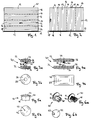
- Fig. 1 shows a ceiling door with a door leaf 10 in its closed position.
- the sections 12 collide longitudinally at joints 14 and are detachably connected there.
- Each section 12 has a left and a right end face 16.
- the sections 12 consist of sheet steel, aluminum sheet or plastic and are profiled by horizontally running bevels so that the door leaf 10 is elastically bendable in the transverse direction of the sections 12. If the door leaf 10 is pushed upwards to open it, it can follow a relatively narrow curve in order to get into a horizontal position, for example near a garage ceiling.
- a rubber seal 18 is provided which, when the door leaf 10 is closed, bears against a floor 19 of the building or against a lower threshold and seals the door.
- a side gate is shown in a similar design.
- the sections 12 are arranged vertically along their length.
- the longitudinal joints 14 and the bevels of the profiling also run vertically.
- the door leaf 10 is therefore rigid in the vertical direction, but elastically bendable in the horizontal direction. It is pushed to the right to open from the position shown in FIG. 2 and runs through a curve in FIG. 2 on the right, as a result of which the door leaf 10 is deflected to the rear perpendicular to the plane of the drawing and in the viewing direction.
- the rubber seal 18 serves to seal the closed door leaf 10 downward, for example with respect to the bottom 19.
- FIGS. 3a and 3b show an embodiment of a sliding piece 20 which has a circular outline and is designed in two parts.
- a first half 22 of the sliding piece 20 has a polished, slightly spherical sliding surface 24, a sound-absorbing intermediate layer 26 made of an elastic rubber material and a projection 28 with an inner bore 30 provided with elastic ribs.
- a second half 32 has a sliding surface 34, a disc-shaped elastic intermediate layer 36 and an extension 38, which is provided with an external toothing.
- the extension 38 is set up to be inserted into the bore 30 of the extension 28, where it is held securely by the inner ribs of the extension 28.
- the two extensions 28 and 38 can have matching screw threads, so that the two halves 22 and 32 of the slide 20 can be screwed together.
- the sliding surface 24 is, as shown in FIG. 3b, slightly spherical and drops off evenly on all sides. It has a central, approximately flat section, which forms the actual sliding section 25 and normally abuts the running or guide surfaces over the entire surface.
- the outline of the slider 24 is circular with a diameter of approximately 15-20 mm.
- the alternative embodiment of the slider 20 shown in FIGS. 4a and 4b has a rectangular outline with rounded corners.
- the sliding surfaces 24 and 34 and the intermediate layers 26 and 36 also have this outline.
- the extension 28 is square or rectangular, so that this slide 20 is secured against rotation when it is inserted into a square or rectangular hole corresponding to the extension 28 on a section 12.
- FIGS. 5a and 5b show a one-piece sliding piece 40 with a sliding surface 42 which has a central, approximately round sliding section 43.
- the section of the slider 40 containing the sliding surface 42 is separated by a circumferential groove 44 from an extension 46 which is designed as a conically tapering section 46.
- This slide 40 is inserted into a bore whose diameter is slightly smaller than the largest outer diameter of the extension 46, so that the slide 40 is held securely in the bore with its groove 44.
- the extension 46 is preferably axially slit several times (not shown in FIG. 5a).
- the groove 44 is only slightly recessed (on the left in FIG. 6a) or completely omitted (on the right in FIG. 6a).
- the extension 46 is approximately designed as a prism with a pentagonal base and has a plurality of axial incisions 48. While the extension 46 widens somewhat in its relaxed state towards its end facing away from the sliding surface 42, it can be radially compressed because of the incisions 48 so that it tapers somewhat towards this end. The extension 46 can then be inserted into a corresponding pentagonal bore 17 (in FIG. 12) or 107 (in FIG. 11), and the slider 40 is reliably held in the bore 17 or 107.
- the extension 46 is eccentrically attached to the slide 40, while in the slide 40 shown on the right in FIG. 6a it is located centrally on the slide 40.
- the slider 40 can be inserted into the bore 17 or 107 in a number of different angular positions and secured there against rotation.
- the sliding surface 42 has an eccentric sliding section 43.
- the sliding section 43 thus comes into contact with a plurality of slideways which are each a few millimeters apart when the gate is opened and closed.
- the fact that the sliding portions 43 can be set to different slideways extends the overall life of the door. This does not result in a higher assembly effort, because if the orientation of the sliding pieces 40 is not taken into account when the gate is being built, the random alignment of the sliding pieces 40 makes it very likely that all possible slideways will be used.
- a plurality of sliding pieces 20 are arranged on the end faces 16 of the sections 12.
- the sliders 20 lie with their sound-absorbing intermediate layers 26 and 36 on both sides of the sections 12.
- the extensions 28 and 38 run through openings (which are not shown in FIG. 7 and are designed similarly to the openings 17 in FIG. 12, but with a circular outline) in the sections 12.
- One half 22, 32 of each slide 20 protrudes beyond the outer boundary levels of the profiled sections 12 and can come into contact with running rails or running surfaces.
- the sections 12 each have a section 52 which is bent at right angles.
- the folded sections 52 lie directly against one another.
- a stiffening profile 50 is pushed onto the folded sections 52. It covers the sharp ends of the folded sections 52 and stiffens the door leaf 10 in the longitudinal direction of the sections 12.
- the bent sections 52 and the stiffening profile 50 are connected to one another by a screw connection 54, but can be removed.
- the stiffening profile 50 increases the wind load capacity of the door, in particular in the case of extra-wide doors.
- Sealing pieces 56 are inserted into the sections of the profile of the door leaf 10, as seen from the outside, and are held on the door sections 12 by the sliding pieces 20.
- the sealing pieces 56 are bent from sheet metal in a J-shape (or made in a corresponding form from plastic) and each have a sealing section 58 which lies approximately in one plane with the outwardly projecting profile sections of the door leaf 10.
- the sealing pieces 56 ensure that snow and rain cannot be whipped through the recessed profile sections into the building, for example the garage.
- sealed sealing pieces (not shown) made of closed-cell elastic foam can also be used.
- FIG. 8 shows part of the guiding mechanism of the door according to an exemplary embodiment.
- the door leaf 10 is located itself in its open position. Only a section of the lowest section 12 and the lower rubber seal 18 of the door leaf 10 is shown in FIG. 8.
- a track 60 is firmly connected to a door frame installed in the building.
- the running rail 60 has a section 62 projecting horizontally into the building, a vertical section 64 near the gate opening and a curved intermediate section 66 connecting these two sections.
- a further guide 68 for the door leaf 10 with a lower surface 70, a middle surface 72, an upper surface 74 and a stop 76 is shown above the curved intermediate section 66.
- a roller 78 of the door leaf 10 is connected via an axis 80 to the lower edge of the lowermost section 12.
- the roller 78 is first guided between the curved intermediate section 66 of the running rail 60 and the lower surface 70.
- the lower surface 70 urges the roller 78 down and causes the door leaf 10 to follow approximately the curvature of the track 60.
- a certain amount of force must be applied in order to deform the door leaf 10, which is elastically bendable in the transverse direction of the sections 12, accordingly.
- the roller 78 has overcome the area of the lower surface 70, it comes into contact with a vertical section 86 of the door frame.
- the roller 78 is then guided between the vertical section 64 of the track 60 and the vertical frame 86.
- the door leaf 10 can be closed vertically downwards by further pulling.
- the vertical frame section 86 also has an attached plastic profile with a sealing lip (similar to the profile 142 and the sealing lip 144 in FIG. 17), on which the sliders 20 slide and rest when the door leaf 10 is closed.
- a sealing lip similar to the profile 142 and the sealing lip 144 in FIG. 17
- rope 82 is hooked into the axis 80 of the roller 78 and, on the other hand, connected to a weight compensation device in the form of a pulley block.
- the weight compensation device shown in FIG. 9 is mounted in an upper horizontal rail 88, close to the opened door leaf 10.
- An upper section of the rail 88 forms the horizontal section 62 of the running rail 60.
- the weight compensation device has a plurality of helical springs 90 which run in parallel and which are inserted on the one hand into a fixed end piece 92 and on the other hand into an end piece 94 which can be displaced in the rail 88.
- the displaceable end piece 94 acts on the cable 82 via a deflection roller 95.
- the springs 90 are shown in their relaxed position with the door leaf 10 open. During the closing of the door leaf 10, the springs 90 are tensioned. The steadily increasing spring force is transmitted through the cable 82 to the lower edge of the door leaf 10, so that the user only has to exert a relatively small, uniform force when closing.
- the cable 82 runs essentially horizontally.
- the cable 82 is deflected in a vertical direction by two deflecting rollers 84, first of all by the upper deflecting roller 84 and, upon further closing, also by the lower deflecting roller 84.
- the cable 82 is thereby curved. If the door leaf 10 is opened again, the cable 82 separates again from the grooves of the deflection rollers 84 shortly before the door leaf 10 has reached its position shown in FIG. 8.
- the door leaf 10 comes into a safe open rest position (locking position), in which there is no risk of the door leaf 10 accidentally closing consists.
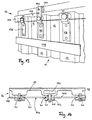
- FIG. 10 shows a side door in which an upper running rail 96 made of powder-coated metal, designed as a lintel frame, has a horizontal running surface 98 for running rollers 100 of the door leaf 10.
- the rollers 100 are attached by means of axes 101 to brackets 102 which are screwed to the upper end faces 16 of the door sections 12.
- the running rail 96 also has a rail section 105 arranged vertically and in the running direction of the door leaf 10, the broad side of which is visible in FIG. 10 forms a sliding region 104.
- Sliding pieces 20, which are arranged on the brackets 102 and further brackets 106, are in contact with the sliding area 104. The sliding pieces 20 ensure smooth door travel when opening and closing the door leaf 10.
- the door leaf 10 Since the door leaf 10, when it is opened or closed, stretches or compresses slightly (approximately by 10 mm to 15 mm in the case of a wide door with a width of approximately 3500 mm to 4500 mm), is a glued-on, sound-absorbing, elastic steel or Plastic tape 108 is provided, which is arranged in the running direction of the sections 12.
- This band 108 is approximately 30 mm to 40 mm wide and approximately 0.3 mm to 0.4 mm thick.
- the band 108 prevents the profiled door leaf from being pushed together or pulled apart ("accordion effect").
- the entire door leaf 10 is soundproofed by gluing the band 108 with a permanently elastic adhesive.
- the tape 108 is glued close to the upper edge of the door leaf 10 and a corresponding tape is located near the lower edge.
- the tape 108 is interrupted at the butt joints 14 of the sections 12. In one alternative embodiment, however, it is guided in one piece over all sections 12, or the strips 108 of two sections are connected to one another across the section boundary.
- the band 108 is a stabilizing element that also has a sound-absorbing effect.
- FIG. 10 shows an alternative embodiment of the connection of the section 12 (in particular for lighter gates), in which an angled section 54 of a section 12 is U-shaped for reinforcement and is guided around the angled section 54 of another section 12.
- a screw connection 54 connects the two sections 12.
- one-piece sliding pieces 40 are used instead of the two-piece sliding pieces 20, preferably those according to FIGS. 6a and 6b with a polygonal extension 46.
- the brackets 106 are designed according to FIG. 11 and have two Fastening bores and a polygonal (here pentagonal) opening 107 corresponding to the extension 46.
- the eccentric sliding sections 43 of the sliding pieces 40 run on different tracks on the sliding area 104, depending on the rotational position in which the sliding piece 40 is inserted into the opening 107.
- a relatively large area of the sliding region 104 comes into contact with the sliding pieces 40, so that the sliding region 104 and an existing sliding coating (for example a powder coating) are less worn out.
- Fig. 12 it is shown that in this alternative embodiment of the gate, the sections 12 also have polygonal fastening openings 17 on their end faces 16, into which sliding pieces 40 can be inserted.
- the end faces 16 and the sliders 40 engage behind the rail section 105.
- FIG. 12 Another embodiment of the connection of two sections 12 at their longitudinal joint 14 is also shown in FIG.
- the section 12 on the left in FIG. 12 has a curved section 53 which projects towards the interior of the building and has an approximately circular cross-section.
- a corresponding section 55 is formed on section 12 on the right in FIG.
- the section 55 encloses the section 53 on its convex outer surface. This forms a hinge that connects the two sections 12 to one another in an articulated manner.
- the two sections 12 with their sections 53 and 55 only need to be hooked into one another.
- the gate shown in FIG. 13 and FIG. 14 corresponds essentially to that of FIG. 10, only that instead of the two-part sliding pieces 20 one-piece sliding pieces 40 are used.
- 13 that the upper edge (shown in broken lines) of the door leaf 10 engages behind the rail section 105.
- the rail section 105 has, in addition to the sliding region 104 visible in FIG. 13 and formed by a broad side of the rail section 105, a further sliding region 109 (FIG. 14) which is formed by the other broad side of the rail section 105 facing away from the viewer in FIG. 13 .
- This further sliding area 109 is in contact with further sliding pieces 40 (shown in broken lines in FIG. 13), which are inserted into openings 17 (FIG. 12) at the upper edge of the door leaf 10.
- the path of the roller 100 on the tread 98 is thus clearly defined, without further measures (for example profiling the tread 98) being necessary.
- Fig. 15 shows again the bilateral guidance of the upper edge of the door leaf 10 through the vertical rail section 105 of the upper track 96, which is firmly connected to a lintel 110 on a ceiling 111 of the building, for example the garage.
- two-piece sliding pieces 20 are again provided.
- a lower edge of the door leaf 10 is guided on the bottom 19.
- a running rail 112 arranged on the floor 19, which is designed here as an angle profile, has a guide section 114 projecting approximately vertically upwards with an inner sliding area 116 and an outer sliding area 118.
- the sliding piece 20 inserted into the lower edge of the door leaf 10 slides on the outer sliding area 118.
- a further sliding piece is located on a bracket 120 which is screwed onto the inside of the door sheet 10 (ie towards the inside of the building) and which is designed similarly to the bracket 106 20, which is in contact with the inner sliding region 116.
- FIG. 16 shows a door with a door leaf 10 which is lighter than that shown in FIG. 15. Because of the lower weight, rollers 100 are not required. Rather, the door leaf 10 can be carried by sliding pieces 20 which are attached to bent, horizontal end sections 124 of the brackets 102 and slide on the running surface 98. In the case of heavy door leaves 10, this arrangement would lead to high wear of the running surface 98 and of the sliding pieces 20 in contact therewith.
- the door leaf 10 shown in FIG. 16 has a section 126 made of wood at the bottom, which is similar to that shown in FIG. 15.
- the floor running rail 112 is designed here as a T-profile and, in addition to the upwardly projecting guide section 114, has a downwardly projecting section 128 anchored in the floor 19.
- a two-part sliding piece 20 attached to the bracket 120 is in contact with the inner sliding area 116.
- a one-piece sliding piece 40 slides on the outer sliding area 118 and is screwed into the wooden section 126 of the door leaf 10 with an extension with a screw thread.
- a divided side frame 130 which has a fastening leg 132, a first running rail 134 and a second running rail 136.
- the fastening leg 132 and the running rails 134 and 136 are screwed together.
- the fastening leg 132 is firmly connected to a side reveal 138 of the building.
- the first running rail 134 has a folded running section 140 projecting in the direction of the door opening.
- a plastic profile 142 with a sliding area for sliding pieces 40 attached to the side edge of the door leaf 10 on its front side (visible side) is attached to the running section 140.
- the plastic profile 142 is used for soundproofing when opening and closing the door leaf 10 and also has an elastic, profiled sealing lip 144 which projects in the direction of the door opening and sealingly abuts the door leaf 10.
- the second running rail 136 has a running section 146 projecting in the direction of the gate opening with an attached, sound-absorbing plastic profile 148.
- a sliding surface formed on the plastic profile is in contact with sliding elements 20, which are attached to the rear of the door leaf 10 at the side edge thereof.
Landscapes
- Engineering & Computer Science (AREA)
- Structural Engineering (AREA)
- Civil Engineering (AREA)
- Mechanical Engineering (AREA)
- Architecture (AREA)
- Wing Frames And Configurations (AREA)
- Specific Sealing Or Ventilating Devices For Doors And Windows (AREA)
- Support Devices For Sliding Doors (AREA)
- Securing Of Glass Panes Or The Like (AREA)
- Springs (AREA)
- Moulds, Cores, Or Mandrels (AREA)
- Load-Engaging Elements For Cranes (AREA)
- Threshing Machine Elements (AREA)
Abstract
Description
- Nach oben oder nach der Seite geführte Rolltore sind bekannt.
- Hier besteht das Torblatt - auch Torpanzer genannt - aus zusammengeschobenen Stahl- oder Aluminiumprofilen (Rolladenprofilen). Das Torblatt ist normalerweise in Führungsschienen geführt. Es kann in diesen unter die Decke eines Bauwerks, beispielsweise einer Garage, geschoben werden. Dabei wird das Torblatt am Sturz der Toreinfahrt auf eine Trommel gewickelt. Der aufgerollte Torblattpanzer benötigt einen verhältnismäßig hohen Sturz von 300 mm bis 400 mm.
- Der gleiche Torblattpanzer kann auch in Führungsschienen nach der Seite geschoben werden. In diesem Fall entsteht auf der linken oder rechten Seite oder der Toreinfahrt hinter der Torlaibung ebenfalls ein Zylinder mit ca. 300 mm bis 400 mm Durchmesser.
- Die Profile dieser Rolladenpanzer sind mindestens auf der Innenseite gewölbt - in der Regel auch auf der Außenseite. In den Laufschienen, die in der Regel U-förmig sind, können Längsgleitbahnen angebracht sein. In der Regel besitzen die Profile an den Stirnseiten aufgesteckte Kunststoffgleiter in starrer, nicht verstellbarer Ausführung ohne Geräuschdämmung.
- Nachteilig ist, daß diese Tore klapprig, undicht, sehr geräuschvoll, platzaufwendig und ohne ansprechende Optik ausgeführt sind.
- Zur Geräuschdämpfung von Rolladen ist es bekannt (deutsches Gebrauchsmuster 1 924 102), auf den Innenseiten der Schenkel einer im Querschnitt U-förmigen Führungsschiene längs der Außenkanten der Führungsschiene verlaufende durchgehende Hohlwülste, vorzugsweise aus weichem Kunststoff vorzusehen, die für den zwischen ihnen laufenden Rolladen eine zweiseitige, nachgiebige Unterlage und Führung bilden. Auch diese Führung führt im Gebrauch zu einer hohen Reibung.
- Decken- oder Seitenlauftore haben in der Regel die gleichen Elemente wie Rolltore. Der Unterschied besteht darin, daß sie nicht aufgewickelt werden, sondern in Laufschienen horizontal unter die Garagendecke laufen oder auf Laufschienen mit Rollen an den Seitenwänden der Garage entlang geführt werden.
- Eine weitere Gruppe von Decken- oder Seitenlauftoren hat einen aus mehreren profilierten Blechbahnen unlösbar zusammengefalzten Blechpanzer. Zum Transport wird dieser Blechpanzer zu einem Zylinder zusammengerollt. Blechpanzer dieser Art gleiten in horizontalen oder vertikalen Führungsschienen. Als Gleitelement wird in den bekannten Fällen ein Rolladengurt verwendet, der an den Stirnseiten des Blechpanzers auf beiden Seiten des Panzers aufgenietet ist. Bei einer Torbreite von 2500 mm - 4000 mm verformt sich je nach Profilierung der Blechpanzer, wenn er um die Kurve gelenkt wird, sehr ungleichmäßig. Die ungleichmäßige Verformung bei bisher auf dem Markt befindlichen ähnlichen Produkten hat zwei Ursachen: Die Profilierung der bekannten Blechpanzer ist derart, daß auf der Außenseite weitgehend plane ebene Flächen von tiefer liegenden, meist halbrunden Sicken abgelöst werden. Diese ungleiche Profilierung und die Länge der Blechbahnen bilden zusammen die Ursache für die Ausbombung des um die Kurve wandernden Blechpanzers.
- Nachteilig ist, daß bei der kleinsten Beschädigung der ganze Panzer ausgewechselt werden muß. Kompliziert ist die Befestigung von vier Rolladengurten, zwei auf jeder Längsseite. Die Betätigung des Tores erfordert einen vergleichsweise hohen Kraftaufwand. Es ist ein gelenkiges Boden- und Sturzprofil erforderlich, um das Torblatt beim Einlaufen in die Kurve kurvengängig zu machen. Der Panzer des Torblattes ist häufig auch wellblechähnlich profiliert, um die Reibung der Gurte gering zu halten. Die Montage der einstückigen Panzer ist schwierig. Es lassen sich keine großen Tore betriebssicher verwirklichen.
- Ferner kann auf der Außenseite des Torpanzers ein Reibband angebracht sein, das an der Innenseite des einen Schenkels der im Querschnitt U-förmigen Laufschiene zur Anlage kommen kann und den Torpanzer führt. Auf der Innenseite des anderen Schenkels der Führungsschiene ist ein Bürstenband angebracht, das zur Abdichtung und ebenfalls zur Führung und zur Geräuschdämpfung dient (US-Patentschrift 4,234,033). Im Gebrauch können sich das Reibband und das Bürstenband mit Schmutz, Wasser oder Eis dauerhaft zusetzen und erhöhen die Reibung sehr stark.
- Eine weitere Gruppe von Decken- und Seitenlauftoren weist einen Torblattpanzer auf, der aus Brettern entsprechender Dicke zusammengesetzt ist, die gelenkartig ineinandergreifen. Auf der Innenseite der Garage werden diese Bretter durch aufgeschraubte elastische Stahlblechbänder zusammengehalten.
- Sowohl die vorher genannten Seiten- oder Deckenlauftore aus Stahlblech als auch die Decken- und Seitenlauftore aus Brettern besitzen in der Regel Rollen oder Röllchen. Je nach dem, ob es sich um Seiten- oder Deckenlauftore handelt, sind die Anordnung der Rollen oder Röllchen und der Durchmesser verschieden.
- Ein übliches Deckensektionaltor hat Sektionen oder Lamellen mit festen steifen Rahmen, die gelenkig miteinander verbunden sind. Die Sektionen besitzen einen speziell ausgebildeten Fingerschutz, Scharniere und Laufrollen. Sie sind die schwersten und die teuersten. Lamellen können nahe ihrem Gelenk mit Gleitern versehen sein, die im Bereich der Gleitbogen diesen zugewandt sind.
- Ein Deckensektionaltor für Garagen mit einer Höhe von ca. 2000 mm besitzt acht Laufrollen und neun bis zwölf Scharniere. Ein Seitenlauftor für eine Garagenbreite von nur 2500 mm hat ca. 30 bis 40 Rollen, ebenso wie ein Deckenlauftor gleicher Größe.
- Der Erfindung liegt das Problem zugrunde, ein Sektionaltor, insbesondere mit elastischen Sektionen, zu schaffen, dem die genannten Mängel nicht anhaften, das laufruhiger ist, sich leichter - auch nach langer Zeit - bewegen läßt, und das auch ästhetisch befriedigende Gestaltungen zuläßt.
- Erfindungsgemäß wird dieses Problem durch ein Decken- oder Seitenlauf-Sektionaltor mit den Merkmalen des Anspruchs 1 gelöst.
- Ein erfindungsgemäßes Tor läßt sich äußerst laufruhig öffnen und schließen.
- Bevorzugt besteht das Torblatt aus mehreren quer-elastischen Sektionen. Dies hat den Vorteil, daß bei der Herstellung, dem Transport und dem Zusammenbau des Tores keine sperrigen Stücke vorliegen. Wegen des geringen Gewichts und der vorteilhaften flächigen Riegelprofilierung kommen die einzelnen Sektionen ohne Querversteifung aus. Das Auswechseln beschädigter Sektionen ist problemlos möglich. Die gesamte Torkonzeption ist somit kostengünstiger.
- Zwischen den Sektionen besteht innen und außen ein vollständiger Fingerschutz, ohne daß zusätzliche Elemente erforderlich sind. Ebensowenig müssen Scharniere aufgeschraubt oder Gummidichtungen zwischen den Sektionen angebracht werden. Bevorzugt ist auch die Torzarge geteilt. Dadurch kann eine Sektion nach der anderen in das offene Zargenprofil eingesetzt und montiert oder bei Reparatur ausgewechselt werden.
- Das Torblatt des neuen Decken- oder Seitenlauftores unterscheidet sich in einer bevorzugten Ausgestaltung von bekannten Torblättern allein schon durch seine quer-elastischen Sektionen und durch die Riegel-Profilierung. Von innen wie von außen hat man den Eindruck, daß das Torblatt aus zusammengesetzten rechteckigen Längs- oder Querriegeln besteht. Bei diesem Sektionaltor sind Trennfugen zwischen den Sektionen kaum erkennbar.
- So besteht beispielsweise ein Torblatt eines Deckensektionaltores für eine Garagendurchfahrtslichte von 2100 mm Höhe in einer bevorzugten Ausführungsform aus vier bis fünf querprofilierten Sektionen, die lösbar miteinander verschraubt sind, wobei die Schrauben von außen nicht sichtbar sind. Die Verbindung der Sektionen kann auch schraubenlos durch einen durchgehenden Scharnierwulst erfolgen. Die Sektionen sind dann lediglich zusammengeschoben.
- Bei diesem Deckensektionaltor befindet sich in der Randzone der Sektionen links und rechts sowohl auf der Ober- wie auf der Unterseite der Profilierung je mindestens ein Kunststoffgleitelement (Gleitstück) pro Profilfläche. Zur Aufnahme des Kunststoffgleitelements sind in den Profilflächen entsprechende runde oder eckig profilierte Durchbrüche vorgesehen. In die runden Durchbrüche werden runde Gleitstücke geklipst, in die profilierten Durchbrüche werden Gleitstücke mit entsprechend profilierten Fortsätzen eingebracht. Die Gleitstücke weisen vorzugsweise eine exzentrische Gleitfläche auf, die durch Drehen der Gleitstücke um einige Millimeter auf eine andere Gleitbahn verlegt werden kann.
- Die Gleitstücke können ein- oder zweiteilig sein. Zur Verwendung kommt insbesondere ein gleitfähiges, marktgängiges Material. Die Gleitflächen sind halbrund oder linsenförmig oder quadratisch und nach vier Seiten ganz leicht ballig.
- Zwischen den beiden Hälften der Gleitstücke befindet sich vorzugsweise je eine elastische schalldämpfende Zwischenlage zur Schalldämmung. Werden die beiden Hälften durch eine Bohrung der profilierten Sektionen gesteckt und zusammengedrückt, verriegeln sie sich durch eine Verzahnung gegenseitig. Nur die schalldämmende Zwischenlage (sowie gegebenenfalls je ein Fortsatz jedes Gleitstücks) steht in Kontakt mit dem Blechpanzer der Sektionen oder mit einem Gleitstückhalter.
- Statt schalldämpfenden Scheiben, die auf die Gleitelemente aufgesteckt werden, kann auch auf den Innenseiten der Sektionen ein schallschluckendes Band von ca. 30 mm bis 40 mm Breite aufgeklebt werden. Fortsätze der Gleitelemente verlaufen durch Bohrungen in diesem Band, um die Gleitelemente mit den Sektionen zu verbinden.
- Vorzugsweise wird ein weiteres schallschluckendes Band auf der Innenseite - dort auf die Sektionen - aufgebracht, wo die Gleitelemente in speziellen Bügeln auf der Innenseite der Sektionen am Sturz und am Boden angebracht werden.
- Durch das Aufbringen dieser schallschluckenden Bänder zwischen den Gleitelementen einerseits und den Befestigungselementen von Gleitelementen und/oder Laufrollen andererseits werden die Schwingungen des Tores und damit die Geräusche beim Öffnen und Schließen zu 50 % bis 60 % reduziert.
- Bei leichteren Toren - Gewicht etwa 10 kg/m2 - können die gleichen Gleitstücke statt Rollen auch als Sturzführung bei Seitensektionaltoren verwendet werden.
- Bei schweren Seitensektionaltoren von ca. 20 kg/m2 werden die Gleitstücke nur für die Bodenführung und für die Sturzführung verwendet. Die Aufhängung am Sturz wird aus Gewichtsgründen nach wie vor von Laufrollen übernommen.
- Der Vorteil der Verwendung von Gleitstücken auch zur Sturzaufhängung beruht im wesentlichen darin, daß man auch bei Garageneinfahrten ohne Sturz durch die Verwendung der Gleitelemente keine Durchfahrtshöhe verliert.
- Die Gleitstücke können auch einstückig sein und in die Bohrungen der Sektionen eingeklipst oder eingeschnappt werden.
- Vorzugsweise sind Sektionen bei Toren mit einer Breite bis zu 4500 mm oder einer Höhe bis zu 3000 mm dadurch verstärkt, daß die Längskanten der einzelnen Sektionen an den Verbindungsstellen ca. 20 mm tief abgekantet sind. Zwei aneinanderstoßende Sektionen werden vorzugsweise dadurch miteinander verbunden, daß ein Verstärkungsprofil über die parallel angeordneten Abkantabschnitte gesteckt und mit diesen Abschnitten verschraubt wird. Auf der Außenseite der Sektionen ist diese Verschraubung unsichtbar.
- Durch diese Verstärkungsprofile ist es möglich, Deckensektionaltore bis zu einer Breite von 4500 mm und Seitensektionaltore bis zu einer Höhe von 3000 mm auszuführen, ohne die Gesamtkonstruktion zu verändern. Die Kurvengangigkeit wird durch die Verstärkungsprofile in keiner Weise nachteilig beeinflußt.
- Ausführungsbeispiele der Erfindung werden nun anhand der schematischen Zeichnungen beschrieben. Es zeigen:
- Fig. 1
- eine Vorderansicht eines Deckensektionaltors,
- Fig. 2
- eine Vorderansicht eines Seitensektionaltors,
- Fig. 3a und Fig. 3b
- einen Querschnitt bzw. eine Vorderansicht eines ersten Ausführungsbeispiels eines aus zwei Hälften zusammensetzbaren Gleitstücks,
- Fig. 4a und Fig. 4b
- einen Querschnitt bzw. eine Vorderansicht eines zweiten Ausführungsbeispiels eines aus zwei Hälften zusammensetzbaren Gleitstücks,
- Fig. 5a und Fig. 5b
- einen Querschnitt bzw. eine Vorderansicht eines ersten Ausführungsbeispiels eines einteiligen Gleitstücks,
- Fig. 6a
- eine perspektivische Ansicht von zwei weiteren Ausführungsbeispielen eines einteiligen Gleitstücks,
- Fig. 6b
- eine Vorderansicht der in Fig. 6a gezeigten Gleitstücke,
- Fig. 7
- eine perspektivische Teilansicht zweier miteinander verbundener Torsektionen mit eingesetzten Gleitstücken,
- Fig. 8 und Fig. 9
- perspektivische Teilansichten eines geöffneten Tores,
- Fig. 10
- eine perspektivische Teilansicht eines ersten Ausführungsbeispiels eines Seitensektionaltores,
- Fig. 11
- eine perspektivische Ansicht eines Haltebügels,
- Fig. 12
- eine perspektivische Teilansicht eines oberen Randabschnittes eines Torblattes,
- Fig. 13
- eine perspektivische Teilansicht eines zweiten Ausführungsbeispiels eines Seitensektionaltores,
- Fig. 14
- eine Draufsicht auf das in Fig. 13 gezeigte Tor,
- Fig. 15
- einen Schnitt entlang einer senkrechten Ebene durch das in Fig. 13 gezeigte Tor,
- Fig. 16
- einen Schnitt entlang einer senkrechten Ebene durch eine weitere Ausführungsvariante des erfindungsgemäßen Seitenlauftores, und
- Fig. 17
- einen Schnitt entlang einer horizontalen Ebene durch eine weitere Ausführungsvariante des erfindungsgemäßen Deckenlauftores.
- Fig. 1 zeigt ein Deckenlauftor mit einem Torblatt 10 in dessen geschlossener Stellung. Vier Sektionen 12 des Torblatts 10 sind sichtbar. Die Sektionen 12 stoßen längs an Stoßstellen 14 zusammen und sind dort lösbar miteinander verbunden. Jede Sektion 12 weist eine linke und eine rechte Stirnseite 16 auf. Die Sektionen 12 bestehen aus Stahlblech, Alublech oder Kunststoff und sind durch horizontal verlaufende Abkantungen so profiliert, daß das Torblatt 10 in Querrichtung der Sektionen 12 elastisch biegbar ist. Wird das Torblatt 10 zum Öffnen nach oben geschoben, so kann es einem relativ engen Kurvenverlauf folgen, um in eine horizontale Lage, beispielsweise nahe einer Garagendecke, zu geraten. Am unteren Rand des Torblatts 10 ist eine Gummidichtung 18 vorgesehen, die bei geschlossenem Torblatt 10 an einem Boden 19 des Bauwerks oder an einer unteren Schwelle anliegt und das Tor abdichtet.
- In Fig. 2 ist ein Seitenlauftor in einer ähnlichen Ausführung gezeigt. Die Sektionen 12 sind hier ihrer Länge nach vertikal angeordnet. Die Längsstoßstellen 14 und die Abkantungen der Profilierung verlaufen ebenfalls vertikal. Das Torblatt 10 ist daher in vertikaler Richtung starr, jedoch in horizontaler Richtung elastisch biegbar. Es wird zum Öffnen aus der in Fig. 2 gezeigten Stellung nach rechts zur Seite geschoben und durchläuft dabei in Fig. 2 rechts eine Kurve, wodurch das Torblatt 10 senkrecht zur Zeichenebene und in Blickrichtung nach hinten umgelenkt wird. Auch hier dient die Gummidichtung 18 dazu, das geschlossene Torblatt 10 nach unten, beispielsweise gegenüber dem Boden 19, abzudichten.
- In Fig. 3a und Fig. 3b ist eine Ausführungsform eines Gleitstücks 20 gezeigt, das einen kreisförmigen Umriß hat und zweiteilig ausgestaltet ist. Eine erste Hälfte 22 des Gleitstücks 20 weist eine polierte, leicht ballige Gleitfläche 24 auf, eine als Scheibe ausgestaltete, schallschluckende Zwischenlage 26 aus einem elastischen Gummimaterial und einen Fortsatz 28 mit einer inneren, mit elastischen Rippen versehenen Bohrung 30. Entsprechend weist eine zweite Hälfte 32 eine Gleitfläche 34, eine scheibenförmige elastische Zwischenlage 36 und einen Fortsatz 38 auf, der mit einer äußeren Zahnung versehen ist. Der Fortsatz 38 ist dazu eingerichtet, in die Bohrung 30 des Fortsatzes 28 eingesteckt zu werden, wo er von den inneren Rippen des Fortsatzes 28 sicher gehalten wird. In einer Ausführungsalternative können die beiden Fortsätze 28 und 38 zueinander passende Schraubengewinde aufweisen, so daß die beiden Hälften 22 und 32 des Gleitstücks 20 miteinander verschraubbar sind.
- Die Gleitfläche 24 ist, wie in Fig. 3b gezeigt, leicht ballig und fällt nach allen Seiten hin gleichmäßig ab. Sie weist einen mittleren, ungefähr ebenen Abschnitt auf, der den eigentlichen Gleitabschnitt 25 bildet und normalerweise vollflächig an Lauf- oder Führungsflächen anliegt. Der Umriß des Gleitstücks 24 ist kreisförmig mit einem Durchmesser von ca. 15 - 20 mm.
- Die in Fig. 4a und 4b gezeigte Ausführungsalternative des Gleitstücks 20 weist einen rechteckigen Umriß mit abgerundeten Ecken auf. Die Gleitflächen 24 und 34 sowie die Zwischenlagen 26 und 36 haben ebenfalls diesen Umriß. Ferner ist der Fortsatz 28 quadratisch oder rechteckig, so daß dieses Gleitstück 20 gegen Verdrehen gesichert ist, wenn es in ein dem Fortsatz 28 entsprechendes, quadratisches oder rechteckiges Loch an einer Sektion 12 eingesetzt wird.
- Fig. 5a und Fig. 5b zeigen ein einteiliges Gleitstück 40 mit einer Gleitfläche 42, die einen mittigen, ungefähr runden Gleitabschnitt 43 aufweist. Der die Gleitfläche 42 enthaltende Abschnitt des Gleitstücks 40 ist durch eine umlaufende Nut 44 von einem Fortsatz 46, der als ein sich konusförmig verjüngender Abschnitt 46 ausgebildet ist, getrennt. Dieses Gleitstück 40 wird in eine Bohrung eingesetzt, deren Durchmesser etwas kleiner ist als der größte Außendurchmesser des Fortsatzes 46, so daß das Gleitstück 40 mit seiner Nut 44 sicher in der Bohrung gehalten ist. Vorzugsweise ist der Fortsatz 46 mehrfach axial geschlitzt (in Fig. 5a nicht dargestellt).
- Bei den in Fig. 6a und Fig. 6b gezeigten Ausführungsalternativen des einteiligen Gleitstücks 40 ist die Nut 44 nur wenig vertieft (in Fig. 6a links) oder ganz weggelassen (in Fig. 6a rechts). Der Fortsatz 46 ist ungefähr als Prisma mit fünfeckiger Grundfläche ausgestaltet und weist mehrere axiale Einschnitte 48 auf. Während sich der Fortsatz 46 in seinem entspannten Zustand zu seinem der Gleitfläche 42 abgewandten Ende hin etwas verbreitert, kann er wegen der Einschnitte 48 radial so weit zusammengedrückt werden, daß er sich zu diesem Ende hin etwas verjüngt. Der Fortsatz 46 kann dann in eine entsprechende fünfeckige Bohrung 17 (in Fig. 12) oder 107 (in Fig. 11) eingesteckt werden, und das Gleitstück 40 wird zuverlässig in der Bohrung 17 oder 107 gehalten.
- In Fig. 6a links ist der Fortsatz 46 exzentrisch am Gleitstück 40 angebracht, während er sich bei dem in Fig. 6a rechts gezeigten Gleitstück 40 mittig am Gleitstück 40 befindet. In beiden Fällen ist das Gleitstück 40 in die Bohrung 17 oder 107 in mehreren unterschiedlichen Winkelpositionen einsetzbar und dort gegen ein Verdrehen gesichert. Die Gleitfläche 42 weist, wie in Fig. 6b gezeigt, einen exzentrischen Gleitabschnitt 43 auf. Je nachdem, wie das Gleitstück 40 in die Bohrung 17 oder 107 eingesetzt ist, kommt somit der Gleitabschnitt 43 beim Öffnen und Schließen des Tores in Kontakt mit iner von mehreren Gleitbahnen, die jeweils um einige Millimeter auseinanderliegen. Dadurch, daß die Gleitabschnitte 43 auf unterschiedliche Gleitbahnen eingestellt sein können, verlängert sich die Gesamtlebensdauer des Tores. Ein höherer Montageaufwand ergibt sich dadurch nicht, denn wenn beim Aufbau der Tores nicht auf die Orientierung der Gleitstücke 40 geachtet wird, werden durch die zufällige Ausrichtung der Gleitstücke 40 mit hoher Wahrscheinlichkeit alle möglichen Gleitbahnen genutzt.
- Wie in Fig. 7 gezeigt ist, sind bei einem Ausführungsbeispiel des erfindungsgemäßen Tores eine Vielzahl von Gleitstücken 20 an den Stirnseiten 16 der Sektionen 12 angeordnet. Die Gleitstücke 20 liegen mit ihren schallschluckenden Zwischenlagen 26 und 36 an beiden Seiten der Sektionen 12 an. Die Fortsätze 28 und 38 laufen durch Öffnungen (die in Fig. 7 nicht gezeigt sind und ähnlich den Öffnungen 17 in Fig. 12, jedoch mit kreisförmigem Umriß, ausgestaltet sind) in den Sektionen 12. Je eine Hälfte 22, 32 jedes Gleitstücks 20 ragt über die äußeren Begrenzungsebenen der profilierten Sektionen 12 hinaus und kann in Kontakt mit Laufschienen oder Laufflächen kommen.
- An den Stoßstellen 14 weisen die Sektionen 12 je einen rechtwinklig abgekanteten Abschnitt 52 auf. Die abgekanteten Abschnitte 52 liegen unmittelbar aneinander an. Ein Versteifungsprofil 50 ist auf die abgekanteten Abschnitte 52 aufgeschoben. Es deckt die scharfen Enden der abgekanteten Abschnitte 52 ab und versteift das Torblatt 10 in Längsrichtung der Sektionen 12. Die abgekanteten Abschnitte 52 und das Versteifungsprofil 50 sind durch eine Verschraubung 54 miteinander fest, aber demontierbar verbunden. Durch das Versteifungsprofil 50 wird, insbesondere bei überbreiten Toren, die Windbelastbarkeit des Tores erhöht.
- In die von außen gesehen zurückspringenden Abschnitte des Profils des Torblatts 10 sind Dichtungsstücke 56 eingelegt und durch die Gleitstücke 20 an den Torsektionen 12 gehalten. Die Dichtungsstücke 56 sind aus Metallblech J-förmig gebogen (oder in entsprechender Form aus Kunststoff gefertigt) und weisen je einen Dichtungsabschnitt 58 auf, der ungefähr in einer Ebene mit den nach außen vorspringenden Profilabschnitten des Torblatts 10 liegt. Durch die Dichtungsstücke 56 wird sichergestellt, daß Schnee und Regen nicht durch die zurückspringenden Profilabschnitte in das Bauwerk, beispielsweise die Garage, hineingepeitscht werden können. In einer Ausführungsalternative können auch aufgeklebte Dichtungsstücke (nicht dargestellt) aus geschlossenzelligem elastischem Schaumstoff verwendet werden.
- In Fig. 8 ist ein Teil der Führungsmechanik des Tores gemäß einem Ausführungsbeispiel dargestellt. Das Torblatt 10 befindet sich in seiner geöffneten Stellung. Von dem Torblatt 10 ist in Fig. 8 nur ein Abschnitt der untersten Sektion 12 sowie der unteren Gummidichtung 18 gezeigt. Eine Laufschiene 60 ist mit einer in das Gebäude eingebauten Torzarge fest verbunden. Die Laufschiene 60 weist einen horizontal in das Gebäude hineinragenden Abschnitt 62, einen vertikalen Abschnitt 64 nahe der Toröffnung und einen diese beiden Abschnitte verbindenden gekrümmten Zwischenabschnitt 66 auf. Über dem gekrümmten Zwischenabschnitt 66 ist eine weitere Führung 68 für das Torblatt 10 mit einer unteren Fläche 70, einer mittleren Fläche 72, einer oberen Fläche 74 und einem Anschlag 76 gezeigt. Eine Laufrolle 78 des Torblatts 10 ist über eine Achse 80 mit dem unteren Rand der untersten Sektion 12 verbunden.
- Wird das Torblatt 10 aus der in Fig. 8 gezeigten Stellung nach unten gezogen, so wird die Laufrolle 78 zunächst zwischen dem gekrümmten Zwischenabschnitt 66 der Laufschiene 60 und der unteren Fläche 70 geführt. Die untere Fläche 70 drängt die Laufrolle 78 nach unten und bewirkt, daß das Torblatt 10 ungefähr der Krümmung der Laufschiene 60 folgt. Dabei muß eine gewisse Kraft aufgewendet werden, um das in Querrichtung der Sektionen 12 elastisch biegbare Torblatt 10 entsprechend zu verformen. Hat die Laufrolle 78 den Bereich der unteren Fläche 70 überwunden, kommt sie in Kontakt mit einem vertikalen Abschnitt 86 der Torzarge. Die Laufrolle 78 wird dann zwischen dem vertikalen Abschnitt 64 der Laufschiene 60 und der Vertikalzarge 86 geführt. Das Torblatt 10 kann durch weiteres Ziehen vertikal nach unten geschlossen werden. Der vertikale Zargenabschnitt 86 weist ferner ein aufgestecktes Kunststoffprofil mit einer Dichtlippe (ähnlich dem Profil 142 und der Dichtlippe 144 in Fig. 17) auf, an dem die Gleitstücke 20 gleiten und bei geschlossenem Torblatt 10 anliegen. Die Gleitstücke 20 berühren bei geschlossenem Torblatt 10 nur dieses Kunststoffprofil und keine Metallteile, so daß das Tor auch bei starkem Wind nicht klappert.
- Um beim Schließen des Tores für einen Gewichtsausgleich des zunehmend senkrecht hängenden Torblatts 10 zu sorgen, ist ein Seil 82 einerseits in die Achse 80 der Laufrolle 78 eingehängt und andererseits mit einer Gewichtsausgleichseinrichtung in Form eines Flaschenzugs verbunden. Die in Fig. 9 gezeigte Gewichtsausgleichseinrichtung ist in einer oberen horizontalen Schiene 88, nahe dem geöffneten Torblatt 10, angebracht. Ein oberer Abschnitt der Schiene 88 bildet den horizontalen Abschnitt 62 der Laufschiene 60. Die Gewichtsausgleichseinrichtung weist mehrere parallel verlaufende Schraubenfedern 90 auf, die einerseits in ein ortsfestes Endstück 92 und andererseits in ein in der Schiene 88 verschiebbares Endstück 94 eingelegt sind. Das verschiebbare Endstück 94 wirkt über eine Umlenkrolle 95 auf das Seil 82.
- In Fig. 9 sind die Federn 90 in ihrer entspannten Position bei geöffnetem Torblatt 10 gezeigt. Während des Schließens des Torblatts 10 werden die Federn 90 gespannt. Die stetig zunehmende Federkraft wird durch das Seil 82 zum unteren Rand des Torblatts 10 übertragen, so daß der Benutzer beim Schließen nur eine relativ geringe, gleichmäßige Kraft ausüben muß.
- In der in Fig. 8 gezeigten geöffneten Stellung des Torblatts 10 verläuft das Seil 82 im wesentlichen waagerecht. Beim Schließen des Torblatts 10 wird das Seil 82 von zwei Umlenkrollen 84 in eine vertikale Richtung umgelenkt, und zwar zunächst von der oberen Umlenkrolle 84 und bei weiterem Schließen auch von der unteren Umlenkrolle 84. Dadurch wird eine Kurvenführung des Seils 82 erreicht. Wird das Torblatt 10 wieder geöffnet, so trennt sich das Seil 82, kurz bevor das Torblatt 10 seine in Fig. 8 gezeigte Stellung erreicht hat, wieder von Laufrillen der Umlenkrollen 84.
- Wird das Torblatt 10 von der in Fig. 8 gezeigten normalen Öffnungsstellung noch etwas zurückgeschoben (in Fig. 8 nach links), bis die Führungsrolle 78 nicht mehr an der unteren Fläche 70 der weiteren Führung 68 anliegt, so richtet sich das Torblatt 10 durch seine federnde Rückstellkraft eben aus. Die Führungsrolle 78 kommt dadurch in Anlage an die obere Fläche 74. Wenn das Torblatt 10 nun in Fig. 8 nach rechts gezogen wird, wird die Führungsrolle 78 zwischen der oberen Fläche 74 und der mittleren Fläche 72 in Richtung auf die Vertikalzarge 86 bis zum Anschlag 76 geführt. Durch die Schräge der mittleren Fläche 72 sowie die Tatsache, daß der Anschlag 76 etwas unter dem untersten Punkt der mittleren Fläche 72 angeordnet ist, kommt das Torblatt 10 in eine sichere geöffnete Ruhestellung (Arretierungsstellung), in der keine Gefahr eines ungewollten Zufallens des Torblatts 10 besteht.
- In Fig. 10 ist ein Seitenlauftor gezeigt, bei dem eine obere, als Sturzzarge ausgebildete Laufschiene 96 aus pulverbeschichtetem Metall eine waagerechte Lauffläche 98 für Laufrollen 100 des Torblatts 10 aufweist. Die Laufrollen 100 sind mittels Achsen 101 an Bügeln 102 angebracht, die mit den oberen Stirnseiten 16 der Torsektionen 12 verschraubt sind. Die Laufschiene 96 weist ferner einen senkrecht und in Laufrichtung des Torblatts 10 angeordneten Schienenabschnitt 105 auf, dessen in Fig. 10 sichtbare Breitseite einen Gleitbereich 104 bildet. Gleitstücke 20, die an den Bügeln 102 sowie weiteren Bügeln 106 angeordnet sind, stehen in Kontakt mit dem Gleitbereich 104. Die Gleitstücke 20 gewährleisten einen ruhigen Torlauf beim Öffnen und Schließen des Torblatts 10.
- Da das Torblatt 10, wenn es auf- oder zugezogen wird, sich leicht streckt oder zusammendrückt (ungefähr um 10 mm bis 15 mm bei einem breiten Tor mit ungefähr 3500 mm bis 4500 mm Breite), ist ein aufgeklebtes, schalldämpfendes, elastisches Stahl- oder Kunststoffband 108 vorgesehen, das in Laufrichtung der Sektionen 12 angeordnet ist. Dieses Band 108 ist ca. 30 mm bis 40 mm breit und ca. 0,3 mm bis 0,4 mm stark. Das Band 108 verhindert das störende Zusammenschieben oder Auseinanderziehen des profilierten Torblatts ("Ziehharmonika-Effekt"). Zusätzlich wird durch das Aufkleben des Bandes 108 mit einem dauerelastischen Klebstoff das ganze Torblatt 10 schallgedämpft. Das Band 108 ist nahe des oberen Randes des Torblatts 10 aufgeklebt, und ein entsprechendes Band befindet sich nahe des unteren Randes.
- Wie in Fig. 10 gezeigt ist, ist das Band 108 an den Stoßfugen 14 der Sektionen 12 unterbrochen. In einer Ausführungsalternative ist es jedoch einstückig über alle Sektionen 12 geleitet, oder die Bänder 108 zweier Sektionen sind über die Sektionsgrenze hinweg miteinander verbunden. Das Band 108 stellt ein Stabilisierungselement dar, das gleichzeitig schalldämmend wirkt.
- Ferner ist in Fig. 10 eine Ausführungsalternative der Verbindung der Sektion 12 (insbesondere für leichtere Tore) gezeigt, bei der ein abgekanteter Abschnitt 54 einer Sektion 12 zur Verstärkung U-förmig ausgebildet und um den abgekanteten Abschnitt 54 einer anderen Sektion 12 herumgeführt. Ebenso wie in Fig. 7 verbindet eine Verschraubung 54 die beiden Sektionen 12.
- In einer Ausführungsalternative des in Fig. 10 gezeigten Tores sind statt der zweiteiligen Gleitstücke 20 einteilige Gleitstücke 40 eingesetzt, und zwar vorzugsweise solche gemäß Fig. 6a und Fig. 6b mit vieleckigem Fortsatz 46. Die Bügel 106 sind gemäß Fig. 11 ausgestaltet und weisen zwei Befestigungsbohrungen sowie eine vieleckige (hier fünfeckige) Öffnung 107 entsprechend dem Fortsatz 46 auf. Wie bereits mit Hinweis auf Fig. 6a und Fig. 6b dargelegt, laufen die exzentrischen Gleitabschnitte 43 der Gleitstücke 40 auf unterschiedlichen Bahnen auf dem Gleitbereich 104, je nachdem, in welcher Drehstellung das Gleitstück 40 in die Öffnung 107 eingesetzt ist. Dadurch kommt insgesamt eine relativ große Fläche des Gleitbereichs 104 in Kontakt mit den Gleitstücken 40, so daß der Gleitbereich 104 und eine darauf vorhandene Gleitbeschichtung (beispielsweise eine Pulverbeschichtung) weniger schnell abgenutzt werden.
- In Fig. 12 ist gezeigt, daß in dieser Ausführungsalternative des Tores auch die Sektionen 12 an ihren Stirnseiten 16 vieleckige Befestigungsöffnungen 17 aufweisen, in die Gleitstücke 40 einsetzbar sind. Die Stirnseiten 16 sowie die Gleitstücke 40 hintergreifen, wie unter Hinweis auf Fig. 13 und Fig. 14 noch beschrieben wird, den Schienenabschnitt 105.
- Ebenfalls in Fig. 12 ist eine weitere Ausführungsvariante der Verbindung zweier Sektionen 12 an ihrer Längsstoßstelle 14 gezeigt. Hier weist die in Fig. 12 linke Sektion 12 einen zum Gebäudeinneren ragenden, gebogenen Abschnitt 53 mit ungefähr kreisbogenförmigem Querschnitt auf. Ein entsprechender Abschnitt 55 ist an der in Fig. 12 rechten Sektion 12 ausgebildet. Der Abschnitt 55 umschließt den Abschnitt 53 an dessen konvexer Außenfläche. Dadurch ist ein Scharnier gebildet, das die beiden Sektionen 12 gelenkig miteinander verbindet. Bei der Montage des Tores brauchen die beiden Sektionen 12 mit ihren Abschnitten 53 und 55 nur ineinander eingehängt zu werden.
- Das in Fig. 13 und Fig. 14 gezeigte Tor entspricht im wesentlichen dem von Fig. 10, nur daß statt der zweiteiligen Gleitstücke 20 einteilige Gleitstücke 40 eingesetzt sind. Aus Fig. 13 geht hervor, daß der (gestrichelt dargestellte) obere Rand des Torblattes 10 den Schienenabschnitt 105 hintergreift. Der Schienenabschnitt 105 weist neben dem in Fig. 13 sichtbaren, von einer Breitseite des Schienenabschnitts 105 gebildeten Gleitbereich 104 einen weiteren Gleitbereich 109 (Fig. 14) auf, der von der anderen, in Fig. 13 dem Betrachter abgewandten Breitseite des Schienenabschnitts 105 gebildet ist. Dieser weitere Gleitbereich 109 steht in Kontakt mit weiteren Gleitstücken 40 (in Fig. 13 gestrichelt dargestellt), die am oberen Rand des Torblattes 10 in Öffnungen 17 (Fig. 12) eingesetzt sind. Durch diese Anordnung ist das Torblatt 10 entlang des Schienenabschnitts 105 sicher geführt. Die Bahn der Laufrolle 100 auf der Lauffläche 98 ist damit eindeutig festgelegt, ohne daß weitere Maßnahmen (beispielsweise eine Profilierung der Lauffläche 98) erforderlich wären.
- Fig. 15 zeigt nochmals die beidseitige Führung des oberen Randes des Torblattes 10 durch den senkrechten Schienenabschnitt 105 der oberen Laufschiene 96, die mit einem Sturz 110 an einer Decke 111 des Gebäudes, beispielsweise der Garage, fest verbunden ist. Im Vergleich zu der in Fig. 13 und Fig. 14 dargestellten Ausführungsform sind statt der einteiligen Gleitstücke 40 wieder zweiteilige Gleitstücke 20 vorgesehen. Ein unterer Rand des Torblatts 10 ist am Boden 19 geführt. Eine am Boden 19 angeordnete Laufschiene 112, die hier als Winkelprofil ausgebildet ist, weist einen ungefähr senkrecht nach oben ragenden Führungsabschnitt 114 mit einem inneren Gleitbereich 116 und einem äußeren Gleitbereich 118 auf. Das in den unteren Rand des Torblatts 10 eingesteckte Gleitstück 20 gleitet an dem äußeren Gleitbereich 118. An einem innen (d.h., zum Gebäudeinneren hin) auf das Torblatt 10 aufgeschraubten Bügel 120, der ähnlich wie die Bügel 106 ausgestaltet ist, befindet sich ein weiteres Gleitstück 20, das mit dem inneren Gleitbereich 116 in Kontakt steht.
- In Fig. 16 ist ein Tor mit einem Torblatt 10 gezeigt, das leichter als das in Fig. 15 dargestellte ist. Wegen des geringeren Gewichts sind keine Laufrollen 100 erforderlich. Das Torblatt 10 kann vielmehr von Gleitstücken 20 getragen werden, die an umgebogenen, waagerechten Endabschnitten 124 der Bügel 102 angebracht sind und auf der Lauffläche 98 gleiten. Bei schweren Torblättern 10 würde diese Anordnung zu einem hohen Verschleiß der Lauffläche 98 und der mit dieser in Kontakt stehenden Gleitstücke 20 führen.
- Das in Fig. 16 dargestellte Torblatt 10 weist unten einen aus Holz bestehenden Abschnitt 126 auf, der ähnlich wie in Fig. 15 dargestellt geführt ist. Die Boden-Laufschiene 112 ist hier als T-Profil ausgestaltet und weist neben dem nach oben ragenden Führungsabschnitt 114 einen im Boden 19 verankerten, nach unten ragenden Abschnitt 128 auf. Wieder steht ein an dem Bügel 120 angebrachtes zweiteiliges Gleitstück 20 in Kontakt mit dem inneren Gleitbereich 116. An dem äußeren Gleitbereich 118 gleitet dagegen ein einteiliges Gleitstück 40, das mit einem Fortsatz mit Schraubengewinde in den Holzabschnitt 126 des Torblatts 10 eingeschraubt ist.
- Bei dem in Fig. 17 gezeigten Deckenlauftor ist eine geteilte Seitenzarge 130 vorgesehen, die einen Befestigungsschenkel 132, eine erste Laufschiene 134 und eine zweite Laufschiene 136 aufweist. Der Befestigungsschenkel 132 und die Laufschienen 134 und 136 sind miteinander verschraubt. Der Befestigungsschenkel 132 ist fest mit einer Seitenlaibung 138 des Gebäudes verbunden. Die erste Laufschiene 134 weist einen abgekanteten, in Richtung der Toröffnung ragenden Laufabschnitt 140 auf. Auf den Laufabschnitt 140 ist ein Kunststoffprofil 142 mit einem Gleitbereich für am seitlichen Rand des Torblattes 10 auf dessen Vorderseite (Sichtseite) angebrachte Gleitstücke 40 aufgesteckt. Das Kunststoffprofil 142 dient zur Schalldämmung beim Öffnen und Schließen des Torblattes 10 und weist ferner eine elastische, profilierte Dichtlippe 144 auf, die in Richtung zur Toröffnung ragt und an dem Torblatt 10 dichtend anliegt. Ähnlich weist die zweite Laufschiene 136 einen in Richtung zur Toröffnung ragenden Laufabschnitt 146 mit einem aufgesteckten, schalldämmenden Kunststoffprofil 148 auf. Eine an dem Kunststoffprofil ausgebildete Gleitfläche steht mit Gleitelementen 20 in Kontakt, die an der Rückseite des Torblattes 10 an dessen seitlichem Rand angebracht sind.
Claims (21)
- Decken- oder Seitenlauf-Sektionaltor mit einem Torblatt (10) insbesondere aus profiliertem Stahlblech, Alublech oder Kunststoff sowie einer Torzarge (86; 130) und mit mindestens einer Laufschiene (60; 96, 112; 134, 136), zur Führung und/oder Abstützung des Torblattes mittels am Torblatt angebrachter Führungs- und/oder Tragelemente,
dadurch gekennzeichnet,
daß das Torblatt (10) längs seiner geführten Kanten mit insbesondere aus Kunststoff bestehenden Gleitstücken (20; 40) versehen ist, von denen beim Öffnen und Schließen des Torblatts (10) zumindest einige in Reib-Kontakt mit einer Laufschiene (60; 96, 112; 134, 136) oder der Torzarge (86; 130) kommen und das Torblatt an diesen Laufschienen senkrecht zu seiner Ebene führen. - Tor nach Anspruch 1,
dadurch gekennzeichnet,
daß die Gleitstücke (20; 40), eine runde, quadratische, rechteckige oder elliptische Form mit mindestens einer balligen Gleitfläche (24, 34; 42) haben. - Tor nach Anspruch 1 oder 2,
dadurch gekennzeichnet,
daß die Gleitstücke (20) zweiteilig zum Anklipsen an das Torblatt (10) oder zum Einschnäppen oder Schraubverbinden ausgeführt sind. - Tor nach einem der Ansprüche 1 bis 3,
dadurch gekennzeichnet,
daß die Gleitstücke (20) mit einer schallschluckenden elastischen Zwischenlage (26, 36) an dem Torblatt (10) aufliegen. - Tor nach Anspruch 4,
dadurch gekennzeichnet,
daß die schallschluckende Zwischenlage (26, 34) ein auf das Torblatt (10) geklebtes schallschluckendes Band ist. - Tor nach einem der Ansprüche 1 bis 5,
dadurch gekennzeichnet,
daß die Gleitflächen (24, 34; 42) der Gleitstücke (20; 40) poliert sind. - Tor nach einem der Ansprüche 1 bis 6,
dadurch gekennzeichnet,
daß das Tor als Deckenlauftor ausgebildet ist und die Gleitstücke (20; 40) an einem linken und einem rechten seitlichen Rand des Torblatts (10) angebracht sind. - Tor nach einem der Ansprüche 1 bis 7,
dadurch gekennzeichnet,
daß das Tor als Deckenlauftor ausgebildet ist und die Laufschiene (60) einen horizontalen Abschnitt (62) und einen vertikalen Abschnitt (64) aufweist, die durch einen gekrümmten Zwischenabschnitt (66) verbunden sind, und daß über dem gekrümmten Zwischenabschnitt (66) eine weitere Führung (68) angeordnet ist. - Tor nach Anspruch 7 oder 8,
dadurch gekennzeichnet,
daß an einem unteren Rand des Torblatts (10) rechts und links je eine Umlenkrolle (78) angebracht ist. - Tor nach Anspruch 9,
dadurch gekennzeichnet,
daß die Umlenkrollen (78) kurz vor Erreichen der Öffnungsstellung des Torblattes (10) zwischen dem gekrümmten Zwischenabschnitt (66) der Laufschiene (60) und einer unteren Fläche (70) der weiteren Führung (68) geführt sind. - Tor nach einem der Ansprüche 7 bis 10,
dadurch gekennzeichnet,
daß der untere Rand (18) des Torblatts (10) über ein Zugseil (82) mit einer Gewichtsausgleichseinrichtung verbunden ist. - Tor nach Anspruch 11,
dadurch gekennzeichnet,
daß Umlenkrollen (84) für das Zugseil (82) vorgesehen sind, um das Zugseil (82) bei teilweise oder ganz geschlossenem Torblatt (10) umzulenken. - Tor nach einem der Ansprüche 1 bis 6,
dadurch gekennzeichnet,
daß das Tor als Seitenlauftor ausgebildet ist und die Gleitstücke (20; 40) teilweise nahe einem oberen Rand des Torblatts (10) und teilweise an Bügeln (102, 106) angebracht sind, die mit dem oberen Rand des Torblatts (10) verbunden sind. - Tor nach einem der Ansprüche 1 bis 13,
dadurch gekennzeichnet,
daß das Torblatt (10) aus mehreren, miteinander lösbar verbundenen Sektionen (12) besteht. - Tor nach Anspruch 14,
dadurch gekennzeichnet,
daß die Sektionen (12) eine Breite von ca. 400 mm bis 600 mm aufweisen. - Tor nach Anspruch 14 oder 15,
dadurch gekennzeichnet,
daß die Sektionen (12) an ihren Längsstoßstellen (14) je einen abgekanteten Abschnitt (52) aufweisen und die aneinander anliegenden abgekanteten Abschnitte (52) miteinander verbunden, vorzugsweise verschraubt, sind. - Tor nach einem der Ansprüche 14 bis 16,
dadurch gekennzeichnet,
daß an den Längsstoßstellen (14) der Sektionen (12) ein Verstärkungsprofil (50) aufgesteckt und vorzugsweise mitverschraubt ist. - Tor nach einem der Ansprüche 14 bis 16,
dadurch gekennzeichnet,
daß die Längsstoßstellen (14) der vorzugsweise elastischen Sektionen (12) schraubenlos mittels eines durchgehenden Scharnierwulsts verbunden sind. - Tor nach einem der Ansprüche 1 bis 18,
dadurch gekennzeichnet,
daß das Torblatt (10) eine Profilierung aufweist und mindestens ein Federstahl- oder Kunststoffband (108) auf das Torblatt (10) aufgeklebt ist, um ein Zusammendrücken oder Auseinanderziehen des Torblatts (10) - Zieharmonikaeffekt - in Laufrichtung während des Öffnens und Schließens zu verhindern. - Tor nach einem der Ansprüche 1 bis 19,
dadurch gekennzeichnet,
daß die Gleitstücke (20; 40) je einen exzentrisch angeordneten Gleitabschnitt (25; 43) aufweisen. - Tor nach Anspruch 20,
dadurch gekennzeichnet,
daß die Gleitstücke (40) je einen ungefähr prismenförmigen Fortsatz (46) mit einer drei-, vier- oder mehreckigen Grundfläche aufweisen.
Applications Claiming Priority (2)
| Application Number | Priority Date | Filing Date | Title |
|---|---|---|---|
| DE19637919A DE19637919C2 (de) | 1996-09-17 | 1996-09-17 | Decken- oder Seitenlauf-Sektionaltor |
| DE19637919 | 1996-09-17 |
Publications (3)
| Publication Number | Publication Date |
|---|---|
| EP0829607A2 true EP0829607A2 (de) | 1998-03-18 |
| EP0829607A3 EP0829607A3 (de) | 1998-06-10 |
| EP0829607B1 EP0829607B1 (de) | 2003-07-23 |
Family
ID=7805926
Family Applications (1)
| Application Number | Title | Priority Date | Filing Date |
|---|---|---|---|
| EP97116191A Expired - Lifetime EP0829607B1 (de) | 1996-09-17 | 1997-09-17 | Sektionaltor mit elastischen Sektionen |
Country Status (7)
| Country | Link |
|---|---|
| EP (1) | EP0829607B1 (de) |
| AT (1) | ATE245754T1 (de) |
| CZ (1) | CZ288597A3 (de) |
| DE (2) | DE19637919C2 (de) |
| ES (1) | ES2202529T3 (de) |
| PL (1) | PL184370B1 (de) |
| PT (1) | PT829607E (de) |
Cited By (3)
| Publication number | Priority date | Publication date | Assignee | Title |
|---|---|---|---|---|
| US7878575B1 (en) * | 2008-02-11 | 2011-02-01 | Roy Wall | Trailer with sliding safety door |
| EP3822441A1 (de) * | 2019-11-13 | 2021-05-19 | Kaviflex, S.L. | Sicherheitsführungssatz für schiebetüren |
| EP4095010A1 (de) * | 2021-05-26 | 2022-11-30 | ULTIMATE Europe Transportation Equipment GmbH | Vorrichtung zum verschliessen von öffnungen |
Family Cites Families (10)
| Publication number | Priority date | Publication date | Assignee | Title |
|---|---|---|---|---|
| US2119011A (en) * | 1937-01-12 | 1938-05-31 | Excel Curtain Company | Blind construction |
| CH196922A (de) * | 1937-10-04 | 1938-04-15 | Therma Ag | Gelenkschiebetüre. |
| US2589938A (en) * | 1948-04-28 | 1952-03-18 | Raymond L Hanrahan | Garage door |
| FR1255093A (fr) * | 1960-01-22 | 1961-03-03 | Jeantils & Gillet Ets | Porte de garage à déplacement latéral à lames agrafées |
| US3129752A (en) * | 1960-11-25 | 1964-04-21 | Whiting Mfg Inc T | Sliding door |
| DE1924102U (de) * | 1965-07-01 | 1965-09-23 | Burbacher Rolladenfabrik Otto | Geraeuschdaemmende laufschiene fuer rollaeden. |
| US4234033A (en) * | 1978-03-08 | 1980-11-18 | Firmaframe Nominees Proprietary Limited | Roller door and frame combination |
| ES2045063T3 (es) * | 1988-11-09 | 1994-01-16 | Doering Erich | Puerta de secciones. |
| US5172744A (en) * | 1989-10-23 | 1992-12-22 | Finch Harry E | Roll-up door system |
| DE9112094U1 (de) * | 1991-09-27 | 1991-11-14 | Siemens AG, 8000 München | Meßvorrichtung zum Ausmessen von Biegeteilen |
-
1996
- 1996-09-17 DE DE19637919A patent/DE19637919C2/de not_active Expired - Fee Related
-
1997
- 1997-09-12 CZ CZ972885A patent/CZ288597A3/cs unknown
- 1997-09-16 PL PL97322124A patent/PL184370B1/pl not_active IP Right Cessation
- 1997-09-17 EP EP97116191A patent/EP0829607B1/de not_active Expired - Lifetime
- 1997-09-17 DE DE59710460T patent/DE59710460D1/de not_active Expired - Fee Related
- 1997-09-17 AT AT97116191T patent/ATE245754T1/de not_active IP Right Cessation
- 1997-09-17 PT PT97116191T patent/PT829607E/pt unknown
- 1997-09-17 ES ES97116191T patent/ES2202529T3/es not_active Expired - Lifetime
Cited By (3)
| Publication number | Priority date | Publication date | Assignee | Title |
|---|---|---|---|---|
| US7878575B1 (en) * | 2008-02-11 | 2011-02-01 | Roy Wall | Trailer with sliding safety door |
| EP3822441A1 (de) * | 2019-11-13 | 2021-05-19 | Kaviflex, S.L. | Sicherheitsführungssatz für schiebetüren |
| EP4095010A1 (de) * | 2021-05-26 | 2022-11-30 | ULTIMATE Europe Transportation Equipment GmbH | Vorrichtung zum verschliessen von öffnungen |
Also Published As
| Publication number | Publication date |
|---|---|
| EP0829607A3 (de) | 1998-06-10 |
| PT829607E (pt) | 2003-12-31 |
| DE19637919C2 (de) | 2000-05-31 |
| EP0829607B1 (de) | 2003-07-23 |
| DE19637919A1 (de) | 1998-03-19 |
| ES2202529T3 (es) | 2004-04-01 |
| DE59710460D1 (de) | 2003-08-28 |
| PL322124A1 (en) | 1998-03-30 |
| ATE245754T1 (de) | 2003-08-15 |
| CZ288597A3 (cs) | 1998-04-15 |
| PL184370B1 (pl) | 2002-10-31 |
Similar Documents
| Publication | Publication Date | Title |
|---|---|---|
| EP0747565A1 (de) | Einbauelement für den Abschluss einer Gebäudeöffnung | |
| AT399200B (de) | Aufhängung für einen rollvorhang | |
| DE69606561T2 (de) | Abschirmvorrichtung | |
| DE9190032U1 (de) | Fenster mit Abschattungselement | |
| DE19707607C2 (de) | Einrichtung mit einem verstellbaren Organ zum Schutz gegen Licht und/oder Witterung und/oder Einbruch und/oder zum Umlenken von Licht | |
| DE19637919C2 (de) | Decken- oder Seitenlauf-Sektionaltor | |
| EP0982465B1 (de) | Über Kopf bewegliches Kipp- oder Schwenktor mit Schutzvorrichtung | |
| DE2651873A1 (de) | Rafflamellenjalousie mit seitenfuehrungsschienen | |
| DE102006005610B4 (de) | Insektenschutzrahmen | |
| DE202007017061U1 (de) | Universell einsetzbarer Rahmen für Vorhänge oder Rollos | |
| DE3301176A1 (de) | Stockrahmen fuer fenster oder tueren mit aufsetzbarem rolladenkasten oder dergleichen | |
| DE3628666A1 (de) | Profilleiste fuer rollaeden | |
| DE3709884A1 (de) | Tor, insbesondere motorisch angetriebenes industrietor | |
| AT517263A1 (de) | Schließvorrichtung für eine Schiebetür | |
| DE19706314A1 (de) | Führungsleiste für Rolladenpanzer | |
| AT413126B (de) | Lamelle einer jalousie bzw. eines raffstores | |
| DE202015009572U1 (de) | Raffstore | |
| WO2005090734A1 (de) | Vorrichtung zum verschluss und/oder zum schutz von bauwerksöffnungen | |
| DE19838205A1 (de) | Sektionaltor | |
| DE10341828B4 (de) | Hohlprofilrahmen für eine Insektenschutztür | |
| EP2089601B1 (de) | Verschlussanordnung | |
| DE29615872U1 (de) | Insektenschutz-Rollo | |
| DE1074253B (de) | FaIt laden | |
| DE202022104201U1 (de) | Moskitonetz mit Kasten, der mit Profilen zum Führen und Erleichtern des Gleitens des Schutznetzes ausgestattet ist | |
| DE20015551U1 (de) | Insektenschutzeinrichtung |
Legal Events
| Date | Code | Title | Description |
|---|---|---|---|
| PUAI | Public reference made under article 153(3) epc to a published international application that has entered the european phase |
Free format text: ORIGINAL CODE: 0009012 |
|
| AK | Designated contracting states |
Kind code of ref document: A2 Designated state(s): AT CH DE ES FR GB IT LI NL PT |
|
| AX | Request for extension of the european patent |
Free format text: AL;LT;LV;RO;SI |
|
| RAP1 | Party data changed (applicant data changed or rights of an application transferred) |
Owner name: NORMSTAHL WERK E. DOERING AG |
|
| PUAL | Search report despatched |
Free format text: ORIGINAL CODE: 0009013 |
|
| AK | Designated contracting states |
Kind code of ref document: A3 Designated state(s): AT BE CH DE DK ES FI FR GB GR IE IT LI LU MC NL PT SE |
|
| AX | Request for extension of the european patent |
Free format text: AL;LT;LV;RO;SI |
|
| RAP1 | Party data changed (applicant data changed or rights of an application transferred) |
Owner name: NORMSTAHL WERK E. DOERING GMBH |
|
| RIN1 | Information on inventor provided before grant (corrected) |
Inventor name: DOERING, ERIC, DR.H.C. |
|
| 17P | Request for examination filed |
Effective date: 19981210 |
|
| AKX | Designation fees paid |
Free format text: AT CH DE ES FR GB IT LI NL PT |
|
| RBV | Designated contracting states (corrected) |
Designated state(s): AT CH DE ES FR GB IT LI NL PT |
|
| 17Q | First examination report despatched |
Effective date: 20000801 |
|
| GRAH | Despatch of communication of intention to grant a patent |
Free format text: ORIGINAL CODE: EPIDOS IGRA |
|
| GRAH | Despatch of communication of intention to grant a patent |
Free format text: ORIGINAL CODE: EPIDOS IGRA |
|
| GRAA | (expected) grant |
Free format text: ORIGINAL CODE: 0009210 |
|
| AK | Designated contracting states |
Designated state(s): AT CH DE ES FR GB IT LI NL PT |
|
| REG | Reference to a national code |
Ref country code: GB Ref legal event code: FG4D Free format text: NOT ENGLISH |
|
| REG | Reference to a national code |
Ref country code: CH Ref legal event code: EP |
|
| RAP2 | Party data changed (patent owner data changed or rights of a patent transferred) |
Owner name: CARDO DOOR PRODUCTION GMBH |
|
| REF | Corresponds to: |
Ref document number: 59710460 Country of ref document: DE Date of ref document: 20030828 Kind code of ref document: P |
|
| NLT2 | Nl: modifications (of names), taken from the european patent patent bulletin |
Owner name: CARDO DOOR PRODUCTION GMBH |
|
| GBT | Gb: translation of ep patent filed (gb section 77(6)(a)/1977) |
Effective date: 20031119 |
|
| REG | Reference to a national code |
Ref country code: ES Ref legal event code: FG2A Ref document number: 2202529 Country of ref document: ES Kind code of ref document: T3 |
|
| ET | Fr: translation filed | ||
| PLBE | No opposition filed within time limit |
Free format text: ORIGINAL CODE: 0009261 |
|
| STAA | Information on the status of an ep patent application or granted ep patent |
Free format text: STATUS: NO OPPOSITION FILED WITHIN TIME LIMIT |
|
| 26N | No opposition filed |
Effective date: 20040426 |
|
| PGFP | Annual fee paid to national office [announced via postgrant information from national office to epo] |
Ref country code: GB Payment date: 20060830 Year of fee payment: 10 |
|
| PGFP | Annual fee paid to national office [announced via postgrant information from national office to epo] |
Ref country code: PT Payment date: 20060912 Year of fee payment: 10 |
|
| PGFP | Annual fee paid to national office [announced via postgrant information from national office to epo] |
Ref country code: NL Payment date: 20060918 Year of fee payment: 10 |
|
| PGFP | Annual fee paid to national office [announced via postgrant information from national office to epo] |
Ref country code: AT Payment date: 20060921 Year of fee payment: 10 |
|
| PGFP | Annual fee paid to national office [announced via postgrant information from national office to epo] |
Ref country code: CH Payment date: 20060925 Year of fee payment: 10 |
|
| PGFP | Annual fee paid to national office [announced via postgrant information from national office to epo] |
Ref country code: ES Payment date: 20060926 Year of fee payment: 10 Ref country code: DE Payment date: 20060926 Year of fee payment: 10 |
|
| PGFP | Annual fee paid to national office [announced via postgrant information from national office to epo] |
Ref country code: IT Payment date: 20060930 Year of fee payment: 10 |
|
| REG | Reference to a national code |
Ref country code: PT Ref legal event code: MM4A Free format text: LAPSE DUE TO NON-PAYMENT OF FEES Effective date: 20080317 |
|
| REG | Reference to a national code |
Ref country code: CH Ref legal event code: PL |
|
| GBPC | Gb: european patent ceased through non-payment of renewal fee |
Effective date: 20070917 |
|
| PG25 | Lapsed in a contracting state [announced via postgrant information from national office to epo] |
Ref country code: PT Free format text: LAPSE BECAUSE OF NON-PAYMENT OF DUE FEES Effective date: 20080317 Ref country code: NL Free format text: LAPSE BECAUSE OF NON-PAYMENT OF DUE FEES Effective date: 20080401 |
|
| NLV4 | Nl: lapsed or anulled due to non-payment of the annual fee |
Effective date: 20080401 |
|
| PG25 | Lapsed in a contracting state [announced via postgrant information from national office to epo] |
Ref country code: AT Free format text: LAPSE BECAUSE OF NON-PAYMENT OF DUE FEES Effective date: 20070917 |
|
| PG25 | Lapsed in a contracting state [announced via postgrant information from national office to epo] |
Ref country code: LI Free format text: LAPSE BECAUSE OF NON-PAYMENT OF DUE FEES Effective date: 20070930 Ref country code: DE Free format text: LAPSE BECAUSE OF NON-PAYMENT OF DUE FEES Effective date: 20080401 Ref country code: CH Free format text: LAPSE BECAUSE OF NON-PAYMENT OF DUE FEES Effective date: 20070930 |
|
| REG | Reference to a national code |
Ref country code: FR Ref legal event code: ST Effective date: 20080531 |
|
| PG25 | Lapsed in a contracting state [announced via postgrant information from national office to epo] |
Ref country code: FR Free format text: LAPSE BECAUSE OF NON-PAYMENT OF DUE FEES Effective date: 20071001 |
|
| PGFP | Annual fee paid to national office [announced via postgrant information from national office to epo] |
Ref country code: FR Payment date: 20060928 Year of fee payment: 10 |
|
| PG25 | Lapsed in a contracting state [announced via postgrant information from national office to epo] |
Ref country code: GB Free format text: LAPSE BECAUSE OF NON-PAYMENT OF DUE FEES Effective date: 20070917 |
|
| REG | Reference to a national code |
Ref country code: ES Ref legal event code: FD2A Effective date: 20070918 |
|
| PG25 | Lapsed in a contracting state [announced via postgrant information from national office to epo] |
Ref country code: ES Free format text: LAPSE BECAUSE OF NON-PAYMENT OF DUE FEES Effective date: 20070918 |
|
| PG25 | Lapsed in a contracting state [announced via postgrant information from national office to epo] |
Ref country code: IT Free format text: LAPSE BECAUSE OF NON-PAYMENT OF DUE FEES Effective date: 20070917 |