EP0829607A2 - Porte sectionnelle avec sections élastiques - Google Patents
Porte sectionnelle avec sections élastiques Download PDFInfo
- Publication number
- EP0829607A2 EP0829607A2 EP97116191A EP97116191A EP0829607A2 EP 0829607 A2 EP0829607 A2 EP 0829607A2 EP 97116191 A EP97116191 A EP 97116191A EP 97116191 A EP97116191 A EP 97116191A EP 0829607 A2 EP0829607 A2 EP 0829607A2
- Authority
- EP
- European Patent Office
- Prior art keywords
- door leaf
- door
- gate according
- sections
- section
- Prior art date
- Legal status (The legal status is an assumption and is not a legal conclusion. Google has not performed a legal analysis and makes no representation as to the accuracy of the status listed.)
- Granted
Links
Images



Classifications
-
- E—FIXED CONSTRUCTIONS
- E06—DOORS, WINDOWS, SHUTTERS, OR ROLLER BLINDS IN GENERAL; LADDERS
- E06B—FIXED OR MOVABLE CLOSURES FOR OPENINGS IN BUILDINGS, VEHICLES, FENCES OR LIKE ENCLOSURES IN GENERAL, e.g. DOORS, WINDOWS, BLINDS, GATES
- E06B3/00—Window sashes, door leaves, or like elements for closing wall or like openings; Layout of fixed or moving closures, e.g. windows in wall or like openings; Features of rigidly-mounted outer frames relating to the mounting of wing frames
- E06B3/32—Arrangements of wings characterised by the manner of movement; Arrangements of movable wings in openings; Features of wings or frames relating solely to the manner of movement of the wing
- E06B3/48—Wings connected at their edges, e.g. foldable wings
- E06B3/485—Sectional doors
-
- E—FIXED CONSTRUCTIONS
- E05—LOCKS; KEYS; WINDOW OR DOOR FITTINGS; SAFES
- E05D—HINGES OR SUSPENSION DEVICES FOR DOORS, WINDOWS OR WINGS
- E05D15/00—Suspension arrangements for wings
- E05D15/06—Suspension arrangements for wings for wings sliding horizontally more or less in their own plane
- E05D15/0621—Details, e.g. suspension or supporting guides
- E05D15/0626—Details, e.g. suspension or supporting guides for wings suspended at the top
- E05D15/0652—Tracks
-
- E—FIXED CONSTRUCTIONS
- E05—LOCKS; KEYS; WINDOW OR DOOR FITTINGS; SAFES
- E05D—HINGES OR SUSPENSION DEVICES FOR DOORS, WINDOWS OR WINGS
- E05D15/00—Suspension arrangements for wings
- E05D15/06—Suspension arrangements for wings for wings sliding horizontally more or less in their own plane
- E05D15/12—Suspension arrangements for wings for wings sliding horizontally more or less in their own plane consisting of parts connected at their edges
-
- E—FIXED CONSTRUCTIONS
- E06—DOORS, WINDOWS, SHUTTERS, OR ROLLER BLINDS IN GENERAL; LADDERS
- E06B—FIXED OR MOVABLE CLOSURES FOR OPENINGS IN BUILDINGS, VEHICLES, FENCES OR LIKE ENCLOSURES IN GENERAL, e.g. DOORS, WINDOWS, BLINDS, GATES
- E06B9/00—Screening or protective devices for wall or similar openings, with or without operating or securing mechanisms; Closures of similar construction
- E06B9/56—Operating, guiding or securing devices or arrangements for roll-type closures; Spring drums; Tape drums; Counterweighting arrangements therefor
- E06B9/58—Guiding devices
-
- E—FIXED CONSTRUCTIONS
- E05—LOCKS; KEYS; WINDOW OR DOOR FITTINGS; SAFES
- E05D—HINGES OR SUSPENSION DEVICES FOR DOORS, WINDOWS OR WINGS
- E05D15/00—Suspension arrangements for wings
- E05D15/16—Suspension arrangements for wings for wings sliding vertically more or less in their own plane
- E05D15/24—Suspension arrangements for wings for wings sliding vertically more or less in their own plane consisting of parts connected at their edges
-
- E—FIXED CONSTRUCTIONS
- E05—LOCKS; KEYS; WINDOW OR DOOR FITTINGS; SAFES
- E05D—HINGES OR SUSPENSION DEVICES FOR DOORS, WINDOWS OR WINGS
- E05D15/00—Suspension arrangements for wings
- E05D15/16—Suspension arrangements for wings for wings sliding vertically more or less in their own plane
- E05D15/24—Suspension arrangements for wings for wings sliding vertically more or less in their own plane consisting of parts connected at their edges
- E05D15/244—Upper part guiding means
- E05D15/246—Upper part guiding means with additional guide rail for producing an additional movement
-
- E—FIXED CONSTRUCTIONS
- E05—LOCKS; KEYS; WINDOW OR DOOR FITTINGS; SAFES
- E05Y—INDEXING SCHEME ASSOCIATED WITH SUBCLASSES E05D AND E05F, RELATING TO CONSTRUCTION ELEMENTS, ELECTRIC CONTROL, POWER SUPPLY, POWER SIGNAL OR TRANSMISSION, USER INTERFACES, MOUNTING OR COUPLING, DETAILS, ACCESSORIES, AUXILIARY OPERATIONS NOT OTHERWISE PROVIDED FOR, APPLICATION THEREOF
- E05Y2900/00—Application of doors, windows, wings or fittings thereof
-
- E—FIXED CONSTRUCTIONS
- E05—LOCKS; KEYS; WINDOW OR DOOR FITTINGS; SAFES
- E05Y—INDEXING SCHEME ASSOCIATED WITH SUBCLASSES E05D AND E05F, RELATING TO CONSTRUCTION ELEMENTS, ELECTRIC CONTROL, POWER SUPPLY, POWER SIGNAL OR TRANSMISSION, USER INTERFACES, MOUNTING OR COUPLING, DETAILS, ACCESSORIES, AUXILIARY OPERATIONS NOT OTHERWISE PROVIDED FOR, APPLICATION THEREOF
- E05Y2900/00—Application of doors, windows, wings or fittings thereof
- E05Y2900/10—Application of doors, windows, wings or fittings thereof for buildings or parts thereof
- E05Y2900/106—Application of doors, windows, wings or fittings thereof for buildings or parts thereof for garages
-
- E—FIXED CONSTRUCTIONS
- E05—LOCKS; KEYS; WINDOW OR DOOR FITTINGS; SAFES
- E05Y—INDEXING SCHEME ASSOCIATED WITH SUBCLASSES E05D AND E05F, RELATING TO CONSTRUCTION ELEMENTS, ELECTRIC CONTROL, POWER SUPPLY, POWER SIGNAL OR TRANSMISSION, USER INTERFACES, MOUNTING OR COUPLING, DETAILS, ACCESSORIES, AUXILIARY OPERATIONS NOT OTHERWISE PROVIDED FOR, APPLICATION THEREOF
- E05Y2900/00—Application of doors, windows, wings or fittings thereof
- E05Y2900/10—Application of doors, windows, wings or fittings thereof for buildings or parts thereof
- E05Y2900/13—Type of wing
- E05Y2900/132—Doors
-
- E—FIXED CONSTRUCTIONS
- E06—DOORS, WINDOWS, SHUTTERS, OR ROLLER BLINDS IN GENERAL; LADDERS
- E06B—FIXED OR MOVABLE CLOSURES FOR OPENINGS IN BUILDINGS, VEHICLES, FENCES OR LIKE ENCLOSURES IN GENERAL, e.g. DOORS, WINDOWS, BLINDS, GATES
- E06B9/00—Screening or protective devices for wall or similar openings, with or without operating or securing mechanisms; Closures of similar construction
- E06B9/56—Operating, guiding or securing devices or arrangements for roll-type closures; Spring drums; Tape drums; Counterweighting arrangements therefor
- E06B9/58—Guiding devices
- E06B2009/587—Mounting of guiding devices to supporting structure
Definitions
- the door leaf - also known as the door curtain - consists of pushed-together steel or aluminum profiles (roller shutter profiles).
- the door leaf is usually guided in guide rails. It can be pushed under the ceiling of a building, for example a garage.
- the door leaf is wound onto a drum at the lintel of the gate entrance.
- the rolled-up door leaf armor requires a relatively high headroom of 300 mm to 400 mm.
- the same door leaf curtain can also be pushed to the side in guide rails.
- a cylinder with a diameter of approx. 300 mm to 400 mm is also created on the left or right side or the gate entrance behind the door reveal.
- roller shutter curtains are arched at least on the inside - usually also on the outside.
- Longitudinal slideways can be attached in the running rails, which are generally U-shaped.
- the profiles have plastic gliders attached to the end faces in a rigid, non-adjustable version without noise insulation.
- roller shutters German utility model 1 924 102
- a continuous hollow beads preferably made of soft plastic, which run along the outer edges of the guide rail in cross section and which form a two-sided, resilient underlay and guide for the roller shutters running between them.
- This guide also leads to high friction in use.
- Ceiling or side doors usually have the same elements as roller doors. The difference is that they are not wound up, but run horizontally under the garage ceiling in runners or are guided along the side walls of the garage on runners with rollers.
- Another group of ceiling or side doors has a sheet metal armor that is inseparably folded from several profiled sheet metal sheets.
- This sheet metal armor is rolled up into a cylinder for transport.
- Sheet metal armor of this type slide in horizontal or vertical guide rails.
- a roller shutter belt is used as a sliding element, which is riveted to the front sides of the sheet metal armor on both sides of the shell.
- the sheet metal armor deforms very unevenly when it is steered around the curve.
- the uneven deformation of similar products previously on the market has two causes:
- the profiling of the known sheet metal armor is such that largely flat, flat surfaces on the outside are replaced by lower-lying, mostly semicircular beads. This uneven profiling and the length of the sheet metal sheets together form the cause of the bombing of the sheet metal armor wandering around the curve.
- the disadvantage is that the entire tank must be replaced if the slightest damage occurs.
- Fastening four roller shutter belts is complicated, two on each long side.
- the operation of the gate requires a comparatively high effort.
- An articulated floor and lintel profile is required to make the door leaf curve when entering the curve.
- the armor of the door leaf is common also profiled like corrugated iron to keep the friction of the belts low.
- the assembly of the one-piece tanks is difficult. Large gates cannot be implemented reliably.
- a friction band can be attached to the outside of the goal armor, which can come to rest on the inside of one leg of the cross-sectionally U-shaped running rail and guides the goal armor.
- a brush band is attached, which is used for sealing and also for guiding and noise reduction (US Pat. No. 4,234,033).
- the friction belt and the brush belt can become permanently clogged with dirt, water or ice and increase the friction very strongly.
- Another group of overhead and side gates has a door leaf armor, which is composed of boards of appropriate thickness, which interlock in an articulated manner. These boards are held together on the inside of the garage by screwed-on elastic steel strips.
- Both the above-mentioned side or ceiling doors made of sheet steel as well as the ceiling and side doors made of boards usually have rollers or rollers. Depending on whether it is a side or overhead door, the arrangement of the rollers or rollers and the diameter are different.
- a common overhead sectional door has sections or slats with rigid rigid frames that are hinged together.
- the sections have a specially designed finger guard, hinges and rollers. They are the heaviest and the most expensive. Slats can be provided near their hinge with gliders that face them in the area of the sliding arches.
- a sectional overhead door for garages with a height of approx. 2000 mm has eight rollers and nine to twelve hinges.
- a side door for a garage width of only 2500 mm has approx. 30 to 40 rollers, just like a ceiling door of the same size.
- the invention is based on the problem of creating a sectional door, in particular with elastic sections, which does not adhere to the above-mentioned defects, which is quieter, can be moved more easily - even after a long time - and which also allows aesthetically satisfactory designs.
- a gate according to the invention can be opened and closed extremely smoothly.
- the door leaf preferably consists of several cross-elastic sections. This has the advantage that there are no bulky pieces in the manufacture, transport and assembly of the gate. Due to the low weight and the advantageous flat bar profile, the individual sections do not require any cross-bracing. It is easy to replace damaged sections. The entire door design is therefore cheaper.
- the door frame is preferably also divided. This allows one section after the other to be inserted and mounted in the open frame profile or to be replaced during repair.
- the door leaf of the new ceiling or side door differs in a preferred embodiment from known ones Door leaves alone thanks to its cross-elastic sections and the latch profile. From the inside as well as from the outside you have the impression that the door leaf consists of assembled rectangular longitudinal or crossbars. With this sectional door, joints between the sections are hardly recognizable.
- a door leaf of a ceiling sectional door for a garage passage light of 2100 mm height consists of four to five cross-profiled sections which are screwed together releasably, the screws not being visible from the outside.
- the sections can also be connected without screws using a continuous hinge bead. The sections are then just pushed together.
- This ceiling sectional door has at least one plastic sliding element (slide) per profile surface in the edge zone of the sections on the left and right both on the top and on the bottom of the profile.
- Corresponding round or square-shaped openings are provided in the profile surfaces to accommodate the plastic sliding element.
- Round sliders are clipped into the round openings, sliders with correspondingly profiled extensions are inserted into the profiled openings.
- the sliders preferably have an eccentric sliding surface, which can be moved to another slideway by rotating the sliders by a few millimeters.
- the sliders can be one or two parts.
- a slidable, marketable material is used.
- the sliding surfaces are semicircular or lenticular or square and slightly spherical on four sides.
- the two halves of the sliders there is preferably an elastic, sound-absorbing intermediate layer for sound insulation. If the two halves are inserted through a hole in the profiled sections and pressed together, they interlock with each other through a toothing. Only the sound-absorbing intermediate layer (and possibly an extension of each slide) is in contact with the sheet metal armor of the sections or with a slide holder.
- a sound-absorbing tape of approx. 30 mm to 40 mm wide can also be glued to the inside of the sections. Extensions of the sliding elements run through holes in this band in order to connect the sliding elements to the sections.
- Another sound-absorbing tape is preferably applied on the inside - to the sections - where the sliding elements are attached to the lintel and floor in special brackets on the inside of the sections.
- the sliders can also be in one piece and clipped or snapped into the bores of the sections.
- sections are preferably reinforced in that the longitudinal edges of the individual sections are chamfered at the connection points to a depth of approximately 20 mm.
- Two abutting sections are preferably connected to one another in that a reinforcing profile is placed over the parallel folded sections and screwed to these sections. This screw connection is invisible on the outside of the sections.
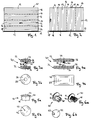
- Fig. 1 shows a ceiling door with a door leaf 10 in its closed position.
- the sections 12 collide longitudinally at joints 14 and are detachably connected there.
- Each section 12 has a left and a right end face 16.
- the sections 12 consist of sheet steel, aluminum sheet or plastic and are profiled by horizontally running bevels so that the door leaf 10 is elastically bendable in the transverse direction of the sections 12. If the door leaf 10 is pushed upwards to open it, it can follow a relatively narrow curve in order to get into a horizontal position, for example near a garage ceiling.
- a rubber seal 18 is provided which, when the door leaf 10 is closed, bears against a floor 19 of the building or against a lower threshold and seals the door.
- a side gate is shown in a similar design.
- the sections 12 are arranged vertically along their length.
- the longitudinal joints 14 and the bevels of the profiling also run vertically.
- the door leaf 10 is therefore rigid in the vertical direction, but elastically bendable in the horizontal direction. It is pushed to the right to open from the position shown in FIG. 2 and runs through a curve in FIG. 2 on the right, as a result of which the door leaf 10 is deflected to the rear perpendicular to the plane of the drawing and in the viewing direction.
- the rubber seal 18 serves to seal the closed door leaf 10 downward, for example with respect to the bottom 19.
- FIGS. 3a and 3b show an embodiment of a sliding piece 20 which has a circular outline and is designed in two parts.
- a first half 22 of the sliding piece 20 has a polished, slightly spherical sliding surface 24, a sound-absorbing intermediate layer 26 made of an elastic rubber material and a projection 28 with an inner bore 30 provided with elastic ribs.
- a second half 32 has a sliding surface 34, a disc-shaped elastic intermediate layer 36 and an extension 38, which is provided with an external toothing.
- the extension 38 is set up to be inserted into the bore 30 of the extension 28, where it is held securely by the inner ribs of the extension 28.
- the two extensions 28 and 38 can have matching screw threads, so that the two halves 22 and 32 of the slide 20 can be screwed together.
- the sliding surface 24 is, as shown in FIG. 3b, slightly spherical and drops off evenly on all sides. It has a central, approximately flat section, which forms the actual sliding section 25 and normally abuts the running or guide surfaces over the entire surface.
- the outline of the slider 24 is circular with a diameter of approximately 15-20 mm.
- the alternative embodiment of the slider 20 shown in FIGS. 4a and 4b has a rectangular outline with rounded corners.
- the sliding surfaces 24 and 34 and the intermediate layers 26 and 36 also have this outline.
- the extension 28 is square or rectangular, so that this slide 20 is secured against rotation when it is inserted into a square or rectangular hole corresponding to the extension 28 on a section 12.
- FIGS. 5a and 5b show a one-piece sliding piece 40 with a sliding surface 42 which has a central, approximately round sliding section 43.
- the section of the slider 40 containing the sliding surface 42 is separated by a circumferential groove 44 from an extension 46 which is designed as a conically tapering section 46.
- This slide 40 is inserted into a bore whose diameter is slightly smaller than the largest outer diameter of the extension 46, so that the slide 40 is held securely in the bore with its groove 44.
- the extension 46 is preferably axially slit several times (not shown in FIG. 5a).
- the groove 44 is only slightly recessed (on the left in FIG. 6a) or completely omitted (on the right in FIG. 6a).
- the extension 46 is approximately designed as a prism with a pentagonal base and has a plurality of axial incisions 48. While the extension 46 widens somewhat in its relaxed state towards its end facing away from the sliding surface 42, it can be radially compressed because of the incisions 48 so that it tapers somewhat towards this end. The extension 46 can then be inserted into a corresponding pentagonal bore 17 (in FIG. 12) or 107 (in FIG. 11), and the slider 40 is reliably held in the bore 17 or 107.
- the extension 46 is eccentrically attached to the slide 40, while in the slide 40 shown on the right in FIG. 6a it is located centrally on the slide 40.
- the slider 40 can be inserted into the bore 17 or 107 in a number of different angular positions and secured there against rotation.
- the sliding surface 42 has an eccentric sliding section 43.
- the sliding section 43 thus comes into contact with a plurality of slideways which are each a few millimeters apart when the gate is opened and closed.
- the fact that the sliding portions 43 can be set to different slideways extends the overall life of the door. This does not result in a higher assembly effort, because if the orientation of the sliding pieces 40 is not taken into account when the gate is being built, the random alignment of the sliding pieces 40 makes it very likely that all possible slideways will be used.
- a plurality of sliding pieces 20 are arranged on the end faces 16 of the sections 12.
- the sliders 20 lie with their sound-absorbing intermediate layers 26 and 36 on both sides of the sections 12.
- the extensions 28 and 38 run through openings (which are not shown in FIG. 7 and are designed similarly to the openings 17 in FIG. 12, but with a circular outline) in the sections 12.
- One half 22, 32 of each slide 20 protrudes beyond the outer boundary levels of the profiled sections 12 and can come into contact with running rails or running surfaces.
- the sections 12 each have a section 52 which is bent at right angles.
- the folded sections 52 lie directly against one another.
- a stiffening profile 50 is pushed onto the folded sections 52. It covers the sharp ends of the folded sections 52 and stiffens the door leaf 10 in the longitudinal direction of the sections 12.
- the bent sections 52 and the stiffening profile 50 are connected to one another by a screw connection 54, but can be removed.
- the stiffening profile 50 increases the wind load capacity of the door, in particular in the case of extra-wide doors.
- Sealing pieces 56 are inserted into the sections of the profile of the door leaf 10, as seen from the outside, and are held on the door sections 12 by the sliding pieces 20.
- the sealing pieces 56 are bent from sheet metal in a J-shape (or made in a corresponding form from plastic) and each have a sealing section 58 which lies approximately in one plane with the outwardly projecting profile sections of the door leaf 10.
- the sealing pieces 56 ensure that snow and rain cannot be whipped through the recessed profile sections into the building, for example the garage.
- sealed sealing pieces (not shown) made of closed-cell elastic foam can also be used.
- FIG. 8 shows part of the guiding mechanism of the door according to an exemplary embodiment.
- the door leaf 10 is located itself in its open position. Only a section of the lowest section 12 and the lower rubber seal 18 of the door leaf 10 is shown in FIG. 8.
- a track 60 is firmly connected to a door frame installed in the building.
- the running rail 60 has a section 62 projecting horizontally into the building, a vertical section 64 near the gate opening and a curved intermediate section 66 connecting these two sections.
- a further guide 68 for the door leaf 10 with a lower surface 70, a middle surface 72, an upper surface 74 and a stop 76 is shown above the curved intermediate section 66.
- a roller 78 of the door leaf 10 is connected via an axis 80 to the lower edge of the lowermost section 12.
- the roller 78 is first guided between the curved intermediate section 66 of the running rail 60 and the lower surface 70.
- the lower surface 70 urges the roller 78 down and causes the door leaf 10 to follow approximately the curvature of the track 60.
- a certain amount of force must be applied in order to deform the door leaf 10, which is elastically bendable in the transverse direction of the sections 12, accordingly.
- the roller 78 has overcome the area of the lower surface 70, it comes into contact with a vertical section 86 of the door frame.
- the roller 78 is then guided between the vertical section 64 of the track 60 and the vertical frame 86.
- the door leaf 10 can be closed vertically downwards by further pulling.
- the vertical frame section 86 also has an attached plastic profile with a sealing lip (similar to the profile 142 and the sealing lip 144 in FIG. 17), on which the sliders 20 slide and rest when the door leaf 10 is closed.
- a sealing lip similar to the profile 142 and the sealing lip 144 in FIG. 17
- rope 82 is hooked into the axis 80 of the roller 78 and, on the other hand, connected to a weight compensation device in the form of a pulley block.
- the weight compensation device shown in FIG. 9 is mounted in an upper horizontal rail 88, close to the opened door leaf 10.
- An upper section of the rail 88 forms the horizontal section 62 of the running rail 60.
- the weight compensation device has a plurality of helical springs 90 which run in parallel and which are inserted on the one hand into a fixed end piece 92 and on the other hand into an end piece 94 which can be displaced in the rail 88.
- the displaceable end piece 94 acts on the cable 82 via a deflection roller 95.
- the springs 90 are shown in their relaxed position with the door leaf 10 open. During the closing of the door leaf 10, the springs 90 are tensioned. The steadily increasing spring force is transmitted through the cable 82 to the lower edge of the door leaf 10, so that the user only has to exert a relatively small, uniform force when closing.
- the cable 82 runs essentially horizontally.
- the cable 82 is deflected in a vertical direction by two deflecting rollers 84, first of all by the upper deflecting roller 84 and, upon further closing, also by the lower deflecting roller 84.
- the cable 82 is thereby curved. If the door leaf 10 is opened again, the cable 82 separates again from the grooves of the deflection rollers 84 shortly before the door leaf 10 has reached its position shown in FIG. 8.
- the door leaf 10 comes into a safe open rest position (locking position), in which there is no risk of the door leaf 10 accidentally closing consists.
- FIG. 10 shows a side door in which an upper running rail 96 made of powder-coated metal, designed as a lintel frame, has a horizontal running surface 98 for running rollers 100 of the door leaf 10.
- the rollers 100 are attached by means of axes 101 to brackets 102 which are screwed to the upper end faces 16 of the door sections 12.
- the running rail 96 also has a rail section 105 arranged vertically and in the running direction of the door leaf 10, the broad side of which is visible in FIG. 10 forms a sliding region 104.
- Sliding pieces 20, which are arranged on the brackets 102 and further brackets 106, are in contact with the sliding area 104. The sliding pieces 20 ensure smooth door travel when opening and closing the door leaf 10.
- the door leaf 10 Since the door leaf 10, when it is opened or closed, stretches or compresses slightly (approximately by 10 mm to 15 mm in the case of a wide door with a width of approximately 3500 mm to 4500 mm), is a glued-on, sound-absorbing, elastic steel or Plastic tape 108 is provided, which is arranged in the running direction of the sections 12.
- This band 108 is approximately 30 mm to 40 mm wide and approximately 0.3 mm to 0.4 mm thick.
- the band 108 prevents the profiled door leaf from being pushed together or pulled apart ("accordion effect").
- the entire door leaf 10 is soundproofed by gluing the band 108 with a permanently elastic adhesive.
- the tape 108 is glued close to the upper edge of the door leaf 10 and a corresponding tape is located near the lower edge.
- the tape 108 is interrupted at the butt joints 14 of the sections 12. In one alternative embodiment, however, it is guided in one piece over all sections 12, or the strips 108 of two sections are connected to one another across the section boundary.
- the band 108 is a stabilizing element that also has a sound-absorbing effect.
- FIG. 10 shows an alternative embodiment of the connection of the section 12 (in particular for lighter gates), in which an angled section 54 of a section 12 is U-shaped for reinforcement and is guided around the angled section 54 of another section 12.
- a screw connection 54 connects the two sections 12.
- one-piece sliding pieces 40 are used instead of the two-piece sliding pieces 20, preferably those according to FIGS. 6a and 6b with a polygonal extension 46.
- the brackets 106 are designed according to FIG. 11 and have two Fastening bores and a polygonal (here pentagonal) opening 107 corresponding to the extension 46.
- the eccentric sliding sections 43 of the sliding pieces 40 run on different tracks on the sliding area 104, depending on the rotational position in which the sliding piece 40 is inserted into the opening 107.
- a relatively large area of the sliding region 104 comes into contact with the sliding pieces 40, so that the sliding region 104 and an existing sliding coating (for example a powder coating) are less worn out.
- Fig. 12 it is shown that in this alternative embodiment of the gate, the sections 12 also have polygonal fastening openings 17 on their end faces 16, into which sliding pieces 40 can be inserted.
- the end faces 16 and the sliders 40 engage behind the rail section 105.
- FIG. 12 Another embodiment of the connection of two sections 12 at their longitudinal joint 14 is also shown in FIG.
- the section 12 on the left in FIG. 12 has a curved section 53 which projects towards the interior of the building and has an approximately circular cross-section.
- a corresponding section 55 is formed on section 12 on the right in FIG.
- the section 55 encloses the section 53 on its convex outer surface. This forms a hinge that connects the two sections 12 to one another in an articulated manner.
- the two sections 12 with their sections 53 and 55 only need to be hooked into one another.
- the gate shown in FIG. 13 and FIG. 14 corresponds essentially to that of FIG. 10, only that instead of the two-part sliding pieces 20 one-piece sliding pieces 40 are used.
- 13 that the upper edge (shown in broken lines) of the door leaf 10 engages behind the rail section 105.
- the rail section 105 has, in addition to the sliding region 104 visible in FIG. 13 and formed by a broad side of the rail section 105, a further sliding region 109 (FIG. 14) which is formed by the other broad side of the rail section 105 facing away from the viewer in FIG. 13 .
- This further sliding area 109 is in contact with further sliding pieces 40 (shown in broken lines in FIG. 13), which are inserted into openings 17 (FIG. 12) at the upper edge of the door leaf 10.
- the path of the roller 100 on the tread 98 is thus clearly defined, without further measures (for example profiling the tread 98) being necessary.
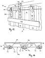
- Fig. 15 shows again the bilateral guidance of the upper edge of the door leaf 10 through the vertical rail section 105 of the upper track 96, which is firmly connected to a lintel 110 on a ceiling 111 of the building, for example the garage.
- two-piece sliding pieces 20 are again provided.
- a lower edge of the door leaf 10 is guided on the bottom 19.
- a running rail 112 arranged on the floor 19, which is designed here as an angle profile, has a guide section 114 projecting approximately vertically upwards with an inner sliding area 116 and an outer sliding area 118.
- the sliding piece 20 inserted into the lower edge of the door leaf 10 slides on the outer sliding area 118.
- a further sliding piece is located on a bracket 120 which is screwed onto the inside of the door sheet 10 (ie towards the inside of the building) and which is designed similarly to the bracket 106 20, which is in contact with the inner sliding region 116.
- FIG. 16 shows a door with a door leaf 10 which is lighter than that shown in FIG. 15. Because of the lower weight, rollers 100 are not required. Rather, the door leaf 10 can be carried by sliding pieces 20 which are attached to bent, horizontal end sections 124 of the brackets 102 and slide on the running surface 98. In the case of heavy door leaves 10, this arrangement would lead to high wear of the running surface 98 and of the sliding pieces 20 in contact therewith.
- the door leaf 10 shown in FIG. 16 has a section 126 made of wood at the bottom, which is similar to that shown in FIG. 15.
- the floor running rail 112 is designed here as a T-profile and, in addition to the upwardly projecting guide section 114, has a downwardly projecting section 128 anchored in the floor 19.
- a two-part sliding piece 20 attached to the bracket 120 is in contact with the inner sliding area 116.
- a one-piece sliding piece 40 slides on the outer sliding area 118 and is screwed into the wooden section 126 of the door leaf 10 with an extension with a screw thread.
- a divided side frame 130 which has a fastening leg 132, a first running rail 134 and a second running rail 136.
- the fastening leg 132 and the running rails 134 and 136 are screwed together.
- the fastening leg 132 is firmly connected to a side reveal 138 of the building.
- the first running rail 134 has a folded running section 140 projecting in the direction of the door opening.
- a plastic profile 142 with a sliding area for sliding pieces 40 attached to the side edge of the door leaf 10 on its front side (visible side) is attached to the running section 140.
- the plastic profile 142 is used for soundproofing when opening and closing the door leaf 10 and also has an elastic, profiled sealing lip 144 which projects in the direction of the door opening and sealingly abuts the door leaf 10.
- the second running rail 136 has a running section 146 projecting in the direction of the gate opening with an attached, sound-absorbing plastic profile 148.
- a sliding surface formed on the plastic profile is in contact with sliding elements 20, which are attached to the rear of the door leaf 10 at the side edge thereof.
Landscapes
- Engineering & Computer Science (AREA)
- Structural Engineering (AREA)
- Civil Engineering (AREA)
- Mechanical Engineering (AREA)
- Architecture (AREA)
- Wing Frames And Configurations (AREA)
- Specific Sealing Or Ventilating Devices For Doors And Windows (AREA)
- Support Devices For Sliding Doors (AREA)
- Securing Of Glass Panes Or The Like (AREA)
- Springs (AREA)
- Moulds, Cores, Or Mandrels (AREA)
- Load-Engaging Elements For Cranes (AREA)
- Threshing Machine Elements (AREA)
Applications Claiming Priority (2)
| Application Number | Priority Date | Filing Date | Title |
|---|---|---|---|
| DE19637919A DE19637919C2 (de) | 1996-09-17 | 1996-09-17 | Decken- oder Seitenlauf-Sektionaltor |
| DE19637919 | 1996-09-17 |
Publications (3)
| Publication Number | Publication Date |
|---|---|
| EP0829607A2 true EP0829607A2 (fr) | 1998-03-18 |
| EP0829607A3 EP0829607A3 (fr) | 1998-06-10 |
| EP0829607B1 EP0829607B1 (fr) | 2003-07-23 |
Family
ID=7805926
Family Applications (1)
| Application Number | Title | Priority Date | Filing Date |
|---|---|---|---|
| EP97116191A Expired - Lifetime EP0829607B1 (fr) | 1996-09-17 | 1997-09-17 | Porte sectionnelle avec sections élastiques |
Country Status (7)
| Country | Link |
|---|---|
| EP (1) | EP0829607B1 (fr) |
| AT (1) | ATE245754T1 (fr) |
| CZ (1) | CZ288597A3 (fr) |
| DE (2) | DE19637919C2 (fr) |
| ES (1) | ES2202529T3 (fr) |
| PL (1) | PL184370B1 (fr) |
| PT (1) | PT829607E (fr) |
Cited By (3)
| Publication number | Priority date | Publication date | Assignee | Title |
|---|---|---|---|---|
| US7878575B1 (en) * | 2008-02-11 | 2011-02-01 | Roy Wall | Trailer with sliding safety door |
| EP3822441A1 (fr) * | 2019-11-13 | 2021-05-19 | Kaviflex, S.L. | Kit de guide de sécurité pour portes coulissantes |
| EP4095010A1 (fr) * | 2021-05-26 | 2022-11-30 | ULTIMATE Europe Transportation Equipment GmbH | Dispositif de fermeture des ouvertures |
Family Cites Families (10)
| Publication number | Priority date | Publication date | Assignee | Title |
|---|---|---|---|---|
| US2119011A (en) * | 1937-01-12 | 1938-05-31 | Excel Curtain Company | Blind construction |
| CH196922A (de) * | 1937-10-04 | 1938-04-15 | Therma Ag | Gelenkschiebetüre. |
| US2589938A (en) * | 1948-04-28 | 1952-03-18 | Raymond L Hanrahan | Garage door |
| FR1255093A (fr) * | 1960-01-22 | 1961-03-03 | Jeantils & Gillet Ets | Porte de garage à déplacement latéral à lames agrafées |
| US3129752A (en) * | 1960-11-25 | 1964-04-21 | Whiting Mfg Inc T | Sliding door |
| DE1924102U (de) * | 1965-07-01 | 1965-09-23 | Burbacher Rolladenfabrik Otto | Geraeuschdaemmende laufschiene fuer rollaeden. |
| US4234033A (en) * | 1978-03-08 | 1980-11-18 | Firmaframe Nominees Proprietary Limited | Roller door and frame combination |
| ES2045063T3 (es) * | 1988-11-09 | 1994-01-16 | Doering Erich | Puerta de secciones. |
| US5172744A (en) * | 1989-10-23 | 1992-12-22 | Finch Harry E | Roll-up door system |
| DE9112094U1 (de) * | 1991-09-27 | 1991-11-14 | Siemens AG, 8000 München | Meßvorrichtung zum Ausmessen von Biegeteilen |
-
1996
- 1996-09-17 DE DE19637919A patent/DE19637919C2/de not_active Expired - Fee Related
-
1997
- 1997-09-12 CZ CZ972885A patent/CZ288597A3/cs unknown
- 1997-09-16 PL PL97322124A patent/PL184370B1/pl not_active IP Right Cessation
- 1997-09-17 EP EP97116191A patent/EP0829607B1/fr not_active Expired - Lifetime
- 1997-09-17 DE DE59710460T patent/DE59710460D1/de not_active Expired - Fee Related
- 1997-09-17 AT AT97116191T patent/ATE245754T1/de not_active IP Right Cessation
- 1997-09-17 PT PT97116191T patent/PT829607E/pt unknown
- 1997-09-17 ES ES97116191T patent/ES2202529T3/es not_active Expired - Lifetime
Cited By (3)
| Publication number | Priority date | Publication date | Assignee | Title |
|---|---|---|---|---|
| US7878575B1 (en) * | 2008-02-11 | 2011-02-01 | Roy Wall | Trailer with sliding safety door |
| EP3822441A1 (fr) * | 2019-11-13 | 2021-05-19 | Kaviflex, S.L. | Kit de guide de sécurité pour portes coulissantes |
| EP4095010A1 (fr) * | 2021-05-26 | 2022-11-30 | ULTIMATE Europe Transportation Equipment GmbH | Dispositif de fermeture des ouvertures |
Also Published As
| Publication number | Publication date |
|---|---|
| EP0829607A3 (fr) | 1998-06-10 |
| PT829607E (pt) | 2003-12-31 |
| DE19637919C2 (de) | 2000-05-31 |
| EP0829607B1 (fr) | 2003-07-23 |
| DE19637919A1 (de) | 1998-03-19 |
| ES2202529T3 (es) | 2004-04-01 |
| DE59710460D1 (de) | 2003-08-28 |
| PL322124A1 (en) | 1998-03-30 |
| ATE245754T1 (de) | 2003-08-15 |
| CZ288597A3 (cs) | 1998-04-15 |
| PL184370B1 (pl) | 2002-10-31 |
Similar Documents
| Publication | Publication Date | Title |
|---|---|---|
| EP0747565A1 (fr) | Elément de montage pour fermer une ouverture d'un bâtiment | |
| AT399200B (de) | Aufhängung für einen rollvorhang | |
| DE69606561T2 (de) | Abschirmvorrichtung | |
| DE9190032U1 (de) | Fenster mit Abschattungselement | |
| DE19707607C2 (de) | Einrichtung mit einem verstellbaren Organ zum Schutz gegen Licht und/oder Witterung und/oder Einbruch und/oder zum Umlenken von Licht | |
| DE19637919C2 (de) | Decken- oder Seitenlauf-Sektionaltor | |
| EP0982465B1 (fr) | Porte basculante avec dispositif de protection | |
| DE2651873A1 (de) | Rafflamellenjalousie mit seitenfuehrungsschienen | |
| DE102006005610B4 (de) | Insektenschutzrahmen | |
| DE202007017061U1 (de) | Universell einsetzbarer Rahmen für Vorhänge oder Rollos | |
| DE3301176A1 (de) | Stockrahmen fuer fenster oder tueren mit aufsetzbarem rolladenkasten oder dergleichen | |
| DE3628666A1 (de) | Profilleiste fuer rollaeden | |
| DE3709884A1 (de) | Tor, insbesondere motorisch angetriebenes industrietor | |
| AT517263A1 (de) | Schließvorrichtung für eine Schiebetür | |
| DE19706314A1 (de) | Führungsleiste für Rolladenpanzer | |
| AT413126B (de) | Lamelle einer jalousie bzw. eines raffstores | |
| DE202015009572U1 (de) | Raffstore | |
| WO2005090734A1 (fr) | Dispositif pour fermer et/ou proteger des ouvertures de construction | |
| DE19838205A1 (de) | Sektionaltor | |
| DE10341828B4 (de) | Hohlprofilrahmen für eine Insektenschutztür | |
| EP2089601B1 (fr) | Dispositif de fermeture | |
| DE29615872U1 (de) | Insektenschutz-Rollo | |
| DE1074253B (de) | FaIt laden | |
| DE202022104201U1 (de) | Moskitonetz mit Kasten, der mit Profilen zum Führen und Erleichtern des Gleitens des Schutznetzes ausgestattet ist | |
| DE20015551U1 (de) | Insektenschutzeinrichtung |
Legal Events
| Date | Code | Title | Description |
|---|---|---|---|
| PUAI | Public reference made under article 153(3) epc to a published international application that has entered the european phase |
Free format text: ORIGINAL CODE: 0009012 |
|
| AK | Designated contracting states |
Kind code of ref document: A2 Designated state(s): AT CH DE ES FR GB IT LI NL PT |
|
| AX | Request for extension of the european patent |
Free format text: AL;LT;LV;RO;SI |
|
| RAP1 | Party data changed (applicant data changed or rights of an application transferred) |
Owner name: NORMSTAHL WERK E. DOERING AG |
|
| PUAL | Search report despatched |
Free format text: ORIGINAL CODE: 0009013 |
|
| AK | Designated contracting states |
Kind code of ref document: A3 Designated state(s): AT BE CH DE DK ES FI FR GB GR IE IT LI LU MC NL PT SE |
|
| AX | Request for extension of the european patent |
Free format text: AL;LT;LV;RO;SI |
|
| RAP1 | Party data changed (applicant data changed or rights of an application transferred) |
Owner name: NORMSTAHL WERK E. DOERING GMBH |
|
| RIN1 | Information on inventor provided before grant (corrected) |
Inventor name: DOERING, ERIC, DR.H.C. |
|
| 17P | Request for examination filed |
Effective date: 19981210 |
|
| AKX | Designation fees paid |
Free format text: AT CH DE ES FR GB IT LI NL PT |
|
| RBV | Designated contracting states (corrected) |
Designated state(s): AT CH DE ES FR GB IT LI NL PT |
|
| 17Q | First examination report despatched |
Effective date: 20000801 |
|
| GRAH | Despatch of communication of intention to grant a patent |
Free format text: ORIGINAL CODE: EPIDOS IGRA |
|
| GRAH | Despatch of communication of intention to grant a patent |
Free format text: ORIGINAL CODE: EPIDOS IGRA |
|
| GRAA | (expected) grant |
Free format text: ORIGINAL CODE: 0009210 |
|
| AK | Designated contracting states |
Designated state(s): AT CH DE ES FR GB IT LI NL PT |
|
| REG | Reference to a national code |
Ref country code: GB Ref legal event code: FG4D Free format text: NOT ENGLISH |
|
| REG | Reference to a national code |
Ref country code: CH Ref legal event code: EP |
|
| RAP2 | Party data changed (patent owner data changed or rights of a patent transferred) |
Owner name: CARDO DOOR PRODUCTION GMBH |
|
| REF | Corresponds to: |
Ref document number: 59710460 Country of ref document: DE Date of ref document: 20030828 Kind code of ref document: P |
|
| NLT2 | Nl: modifications (of names), taken from the european patent patent bulletin |
Owner name: CARDO DOOR PRODUCTION GMBH |
|
| GBT | Gb: translation of ep patent filed (gb section 77(6)(a)/1977) |
Effective date: 20031119 |
|
| REG | Reference to a national code |
Ref country code: ES Ref legal event code: FG2A Ref document number: 2202529 Country of ref document: ES Kind code of ref document: T3 |
|
| ET | Fr: translation filed | ||
| PLBE | No opposition filed within time limit |
Free format text: ORIGINAL CODE: 0009261 |
|
| STAA | Information on the status of an ep patent application or granted ep patent |
Free format text: STATUS: NO OPPOSITION FILED WITHIN TIME LIMIT |
|
| 26N | No opposition filed |
Effective date: 20040426 |
|
| PGFP | Annual fee paid to national office [announced via postgrant information from national office to epo] |
Ref country code: GB Payment date: 20060830 Year of fee payment: 10 |
|
| PGFP | Annual fee paid to national office [announced via postgrant information from national office to epo] |
Ref country code: PT Payment date: 20060912 Year of fee payment: 10 |
|
| PGFP | Annual fee paid to national office [announced via postgrant information from national office to epo] |
Ref country code: NL Payment date: 20060918 Year of fee payment: 10 |
|
| PGFP | Annual fee paid to national office [announced via postgrant information from national office to epo] |
Ref country code: AT Payment date: 20060921 Year of fee payment: 10 |
|
| PGFP | Annual fee paid to national office [announced via postgrant information from national office to epo] |
Ref country code: CH Payment date: 20060925 Year of fee payment: 10 |
|
| PGFP | Annual fee paid to national office [announced via postgrant information from national office to epo] |
Ref country code: ES Payment date: 20060926 Year of fee payment: 10 Ref country code: DE Payment date: 20060926 Year of fee payment: 10 |
|
| PGFP | Annual fee paid to national office [announced via postgrant information from national office to epo] |
Ref country code: IT Payment date: 20060930 Year of fee payment: 10 |
|
| REG | Reference to a national code |
Ref country code: PT Ref legal event code: MM4A Free format text: LAPSE DUE TO NON-PAYMENT OF FEES Effective date: 20080317 |
|
| REG | Reference to a national code |
Ref country code: CH Ref legal event code: PL |
|
| GBPC | Gb: european patent ceased through non-payment of renewal fee |
Effective date: 20070917 |
|
| PG25 | Lapsed in a contracting state [announced via postgrant information from national office to epo] |
Ref country code: PT Free format text: LAPSE BECAUSE OF NON-PAYMENT OF DUE FEES Effective date: 20080317 Ref country code: NL Free format text: LAPSE BECAUSE OF NON-PAYMENT OF DUE FEES Effective date: 20080401 |
|
| NLV4 | Nl: lapsed or anulled due to non-payment of the annual fee |
Effective date: 20080401 |
|
| PG25 | Lapsed in a contracting state [announced via postgrant information from national office to epo] |
Ref country code: AT Free format text: LAPSE BECAUSE OF NON-PAYMENT OF DUE FEES Effective date: 20070917 |
|
| PG25 | Lapsed in a contracting state [announced via postgrant information from national office to epo] |
Ref country code: LI Free format text: LAPSE BECAUSE OF NON-PAYMENT OF DUE FEES Effective date: 20070930 Ref country code: DE Free format text: LAPSE BECAUSE OF NON-PAYMENT OF DUE FEES Effective date: 20080401 Ref country code: CH Free format text: LAPSE BECAUSE OF NON-PAYMENT OF DUE FEES Effective date: 20070930 |
|
| REG | Reference to a national code |
Ref country code: FR Ref legal event code: ST Effective date: 20080531 |
|
| PG25 | Lapsed in a contracting state [announced via postgrant information from national office to epo] |
Ref country code: FR Free format text: LAPSE BECAUSE OF NON-PAYMENT OF DUE FEES Effective date: 20071001 |
|
| PGFP | Annual fee paid to national office [announced via postgrant information from national office to epo] |
Ref country code: FR Payment date: 20060928 Year of fee payment: 10 |
|
| PG25 | Lapsed in a contracting state [announced via postgrant information from national office to epo] |
Ref country code: GB Free format text: LAPSE BECAUSE OF NON-PAYMENT OF DUE FEES Effective date: 20070917 |
|
| REG | Reference to a national code |
Ref country code: ES Ref legal event code: FD2A Effective date: 20070918 |
|
| PG25 | Lapsed in a contracting state [announced via postgrant information from national office to epo] |
Ref country code: ES Free format text: LAPSE BECAUSE OF NON-PAYMENT OF DUE FEES Effective date: 20070918 |
|
| PG25 | Lapsed in a contracting state [announced via postgrant information from national office to epo] |
Ref country code: IT Free format text: LAPSE BECAUSE OF NON-PAYMENT OF DUE FEES Effective date: 20070917 |