EP0834687A1 - Joint métallique pourvu d'un bourrelet d'étanchéité et d'une partie de protection du bourrelet - Google Patents
Joint métallique pourvu d'un bourrelet d'étanchéité et d'une partie de protection du bourrelet Download PDFInfo
- Publication number
- EP0834687A1 EP0834687A1 EP97307753A EP97307753A EP0834687A1 EP 0834687 A1 EP0834687 A1 EP 0834687A1 EP 97307753 A EP97307753 A EP 97307753A EP 97307753 A EP97307753 A EP 97307753A EP 0834687 A1 EP0834687 A1 EP 0834687A1
- Authority
- EP
- European Patent Office
- Prior art keywords
- bead
- protecting portion
- gasket
- metal plate
- metal
- Prior art date
- Legal status (The legal status is an assumption and is not a legal conclusion. Google has not performed a legal analysis and makes no representation as to the accuracy of the status listed.)
- Granted
Links
Images
Classifications
-
- F—MECHANICAL ENGINEERING; LIGHTING; HEATING; WEAPONS; BLASTING
- F16—ENGINEERING ELEMENTS AND UNITS; GENERAL MEASURES FOR PRODUCING AND MAINTAINING EFFECTIVE FUNCTIONING OF MACHINES OR INSTALLATIONS; THERMAL INSULATION IN GENERAL
- F16J—PISTONS; CYLINDERS; SEALINGS
- F16J15/00—Sealings
- F16J15/02—Sealings between relatively-stationary surfaces
- F16J15/06—Sealings between relatively-stationary surfaces with solid packing compressed between sealing surfaces
- F16J15/08—Sealings between relatively-stationary surfaces with solid packing compressed between sealing surfaces with exclusively metal packing
-
- F—MECHANICAL ENGINEERING; LIGHTING; HEATING; WEAPONS; BLASTING
- F16—ENGINEERING ELEMENTS AND UNITS; GENERAL MEASURES FOR PRODUCING AND MAINTAINING EFFECTIVE FUNCTIONING OF MACHINES OR INSTALLATIONS; THERMAL INSULATION IN GENERAL
- F16J—PISTONS; CYLINDERS; SEALINGS
- F16J15/00—Sealings
- F16J15/02—Sealings between relatively-stationary surfaces
- F16J15/06—Sealings between relatively-stationary surfaces with solid packing compressed between sealing surfaces
- F16J15/08—Sealings between relatively-stationary surfaces with solid packing compressed between sealing surfaces with exclusively metal packing
- F16J15/0818—Flat gaskets
-
- F—MECHANICAL ENGINEERING; LIGHTING; HEATING; WEAPONS; BLASTING
- F16—ENGINEERING ELEMENTS AND UNITS; GENERAL MEASURES FOR PRODUCING AND MAINTAINING EFFECTIVE FUNCTIONING OF MACHINES OR INSTALLATIONS; THERMAL INSULATION IN GENERAL
- F16J—PISTONS; CYLINDERS; SEALINGS
- F16J15/00—Sealings
- F16J15/02—Sealings between relatively-stationary surfaces
- F16J15/06—Sealings between relatively-stationary surfaces with solid packing compressed between sealing surfaces
- F16J15/08—Sealings between relatively-stationary surfaces with solid packing compressed between sealing surfaces with exclusively metal packing
- F16J15/0818—Flat gaskets
- F16J2015/0843—Flat gaskets with an edge portion folded over the plate itself
-
- F—MECHANICAL ENGINEERING; LIGHTING; HEATING; WEAPONS; BLASTING
- F16—ENGINEERING ELEMENTS AND UNITS; GENERAL MEASURES FOR PRODUCING AND MAINTAINING EFFECTIVE FUNCTIONING OF MACHINES OR INSTALLATIONS; THERMAL INSULATION IN GENERAL
- F16J—PISTONS; CYLINDERS; SEALINGS
- F16J15/00—Sealings
- F16J15/02—Sealings between relatively-stationary surfaces
- F16J15/06—Sealings between relatively-stationary surfaces with solid packing compressed between sealing surfaces
- F16J15/08—Sealings between relatively-stationary surfaces with solid packing compressed between sealing surfaces with exclusively metal packing
- F16J15/0818—Flat gaskets
- F16J2015/085—Flat gaskets without fold over
Definitions
- the present invention relates to a metal gasket with a sealing bead and a seal protecting portion, in particular a single metal plate with a compressible sealing bead and a seal protecting portion for protecting the sealing bead.
- the invention can be applied to gaskets for sealing a narrow area as well as a wide area, such as a pipe connecting gasket and a cylinder head gasket for an internal combustion engine.
- the engines have been developed to provide high power with light weight. Since metal gaskets or metal laminate gaskets are strong against high pressure and high temperature, the metal gaskets have been used widely for the engines. To provide high power with light weight engine, the gasket must be made thin, and seal around the cylinder bores tightly.
- one or more metal plates have sealing beads around the cylinder bores, and protecting portions for preventing deformation or creep relaxation of the beads are formed near the sealing beads.
- a metal laminate gasket as disclosed in Japanese Patent Publication (KOKAI) No. 8-100859 is formed of three metal plates laminated together, wherein upper and lower metal plates have beads around holes to be sealed, and a middle plate thicker than the upper and lower plates includes bead protecting portions, which do not deform when the gasket is compressed.
- the beads extend toward the middle plate, and the bead protecting portions are located at both sides of each bead. Since the beads are not completely compressed by the bead protecting portions when the gasket is tightened, the beads seal around the holes without creep relaxation.
- the above gasket is formed of three plates, or it requires at least two plates, one plate for the bead and the other plate for the bead protecting portion. Since the gasket becomes relatively thick, it is possible to use such a gasket as a large cylinder head gasket, but the gasket is not suitable as a small gasket.
- the gasket since the above gasket is formed of three metal plates with different functions, the gasket operates as a combination of the three metal plates. Therefore, one of the metal plates can not be selected and used as a single plate gasket because of providing insufficient or improper sealing around the hole.
- an edge portion of a metal plate may be turned over a base of the metal plate to form a seal portion or a bead protecting portion around the edge portion.
- the bead protecting portion can be formed only at the edge portion of the gasket, the structure of the gasket, i.e. locations of the bead and the bead protecting portion, is limited.
- the present invention has been made in view of the above conventional gaskets, and an object of the invention is to provide a metal gasket, which is thin and can securely seal around a hole while protecting a bead by a bead protecting portion.
- Another object of the invention is to provide a metal gasket as stated above, wherein a sealing bead and a bead protecting portion for the sealing bead can be formed in desired portions in a metal plate.
- a further object of the invention is to provide a metal gasket as stated above, which is suitable for sealing a small area like a pipe connecting gasket as well as a large area like a cylinder head gasket.
- a metal gasket of the invention is used for an internal combustion engine, as a cylinder head gasket or a pipe connecting gasket.
- the gasket is formed of a metal plate for constituting the metal gasket, which includes a base portion extending substantially throughout an entire area to be sealed.
- the gasket includes a bead protecting portion extending outwardly from a front surface of the base portion, and a sealing bead adjacent to the bead protecting portion.
- the bead protecting portion is formed in the metal plate to have no substantial compressibility, while the sealing bead has a compressibility.
- the bead protecting portion provides a surface pressure without substantial resiliency, and the sealing bead provides a surface pressure with resiliency. Since the sealing bead is protected from being completely compressed by the bead protecting portion, creep relaxation of the sealing bead is prevented.
- the metal plate can operate as a single plate gasket with full functions. Also, the metal gasket can be relatively easily and economically formed.
- the bead protecting portion is a non-compressible projection formed in a middle of the metal plate without turning an edge of the metal plate. Also, the bead protecting portion and the sealing bead surround a hole for sealing the same. Further, a stepped portion may be formed in the metal plate to surround the sealing bead.
- the bead protecting portion may completely surround the hole without interruption. In this case, the bead protecting portion also seals around the hole. On the other hand, the bead protecting portion may surround the hole with interruptions.
- the metal plate with the bead protecting portion and the sealing bead can be used as a single plate gasket, but the metal plate may be laminated with one or more metal plates to form a metal laminate gasket.
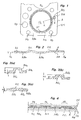
- the gasket A is a cylinder head gasket, and includes a plurality of cylinder bores Hc, water holes Hw, oil holes Ho (not shown), bolt holes (Hb), push rod holes Hp, and so on, as in the conventional gasket.
- the gasket A is formed of a single metal plate A10, preferably a stainless steel plate, extending throughout an entire area to be sealed.
- the metal plate A10 includes a base portion A10a, a bead protecting portion A11 situated around the cylinder bore Hc, a bead A12 located around the bead protecting portion A11, and a stepped bead A13 located around the water hole Hw.
- the base portion A10a substantially covers the metal plate A10 except the bead protecting portion A11, the bead A12 and the stepped bead A13.
- the bead protecting portion A11 projects outwardly from an upper surface of the plate A10, and is made thick so that the bead protecting portion A11 is not substantially compressed when the gasket A is tightened.
- Figs. 3(a)-3(c) show the process for forming the bead protecting portion A11.
- a projection A11a is formed by a press to project from the outer surface of the plate A10 (Fig. 3(a)) for the height H.
- the projection A11a is pressed to the thickness H1 to form a projection A11b, which is again pressed to the thickness H2.
- foot portions A11c having the thickness t as in the metal plate A10 increases the thickness step by step to increase the strength thereof.
- the foot portions A11c receive processing deformation as well, so that the foot portions A11c have sufficient strength. Therefore, when the gasket A is compressed in use, the bead protecting portion A11 is not substantially compressed any more, i.e. non-compressible, to thereby protect the bead A12.
- the bead A12 is formed around the bead protecting portion A11, and the stepped bead A13 is formed around the water hole Hw.
- the bead A12 and the stepped bead A13 are formed by a press, as in the conventional method.
- the bead protecting portion A11 When the gasket A is situated between a cylinder head CH and a cylinder block CB and is tightened as shown in Fig. 4, the bead protecting portion A11 is not substantially compressed, and provides a surface pressure P3.
- the bead A12 is compressed to the height H2 of the bead protecting portion A11, and is not compressed further.
- the bead protecting portion A11 operates to protect the bead A12 from complete flattening, i.e. creep relaxation of the bead A12 and to securely seal around the cylinder bore Hc.
- the bead A12 provides resilient surface pressure P4.
- the stepped bead A13 provides resilient surface pressure P5 to seal around the water hole Hw.
- Fig. 5 shows a metal gasket B used as a cylinder head gasket, similar to the gasket A. Fig. 5, however, shows only the portion around the cylinder bore Hc, excluding the structure around the water hole Hw.
- the gasket B is formed of one metal plate B10, and includes a base portion B10a, a bead protecting portion B11 situated around the cylinder bore Hc, and two beads B12 located on both sides of the bead protecting portion B11.
- the beads B12 and the bead protecting portion B11 surround the cylinder bore Hc to securely seal therearound.
- the bead protecting portion B11 has a shape similar to an inverse trapezoid, and a compressible space therein.
- the bead protecting portion B11 is slightly compressed such that an upper portion B11a is fully pressed onto the base portion B10a.
- the bead protecting portion B11 is not completely flattened to the thickness same as the base portion B10a.
- the beads B12 are compressed to the thickness of the bead protecting portion B11 to seal around the cylinder bore Hc.
- the beads B12 resiliently seal around the cylinder bore Hc, while the bead protecting portion B11 seals without resiliency.
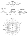
- the bead protecting portion A11 has a rectangular shape and is formed as shown in Figs. 3(a)-3(c). However, the gasket A may have a bead protecting portion C11 formed as shown in Figs. 6(a)-6(c).
- a projection C11a is formed on a metal plate C10
- the projection C11a is pushed diagonally and leftwardly as shown in Fig. 6(b), and then the projection C11a is compressed downwardly.
- one leg C11b is disposed on a base portion C10a
- the other leg C11c is stretched to thereby form the bead protecting portion C11. Since a part of the bead protecting portion C11 is disposed on the base portion C10a, even if high tightening pressure is applied to the bead protecting portion C11, the thickness of the bead protecting portion C11 does not reduce.
- the bead protecting portion C11 is useful for a gasket which receives a high tightening pressure.
- Fig. 7 is a third embodiment of a metal gasket D of the invention.
- the gasket D is used for connecting a pipe, such as an exhaust pipe, and includes a hole Hm, and a plurality of bolt holes Hb'.
- the gasket D is formed of a single metal plate D10, and includes a base portion D10a, bead protecting portions D11 situated around the hole lim, a bead D12 located around the bead protecting portions D11, and a stepped bead D13 located around the bead D12, similar to the gasket A.
- the bead protecting portions D11 are not continuous, and spaced apart from each other.
- the bead protecting portions D11 are formed on an imaginary line concentrically to the hole Hm, the bead protecting portions D11 are interrupted.
- a section line extending radially outwardly from a center of the hole Hm and passing through one of the bead protecting portions D11 is taken, the section appears as in Figs 1 and 2.
- the bead protecting portions D11 are not continuous, but the bead D12 located outside the bead protecting portions D11 are not completely compressed when the gasket D is tightened. Therefore, the bead protecting portions D11 operate as in the bead protecting portion A11. Although the bead protecting portions D11 do not seal around the hole Hm unlike the gasket A, since the stepped bead D13 is formed around the bead D12, the gasket D substantially completely seals around the hole Hm.
- the gasket of the invention is formed of a single plate, but the non-compressible bead protecting portion and the compressible bead are formed on the single metal plate.
- the non-compressible bead protecting portion prevents the sealing bead from being completely compressed. Therefore, the sealing bead securely seals around the hole without substantial creep relaxation.
- the non-compressible bead protecting portion is continuously formed around the hole, the bead protecting portion also seals around the hole.
- the gasket is useful when it is formed of the single plate.
- the single plate gasket of the invention may be combined with one or more plates to constitute a metal laminate gasket.
- the bead protecting portion may be situated radially outwardly of a compressible bead.
- the bead protecting portion A11 has solid foot portions A11c which are wider in the radial direction than the thickness of the plate thereat, thus, assisting the incompressibility thereof.
- the radial width of the foot portions A11c may be greater than the thickness ⁇ t ⁇ of the plate and also of the protecting portion A11.
Landscapes
- Engineering & Computer Science (AREA)
- General Engineering & Computer Science (AREA)
- Mechanical Engineering (AREA)
- Gasket Seals (AREA)
Applications Claiming Priority (3)
| Application Number | Priority Date | Filing Date | Title |
|---|---|---|---|
| JP266210/96 | 1996-10-07 | ||
| JP26621096 | 1996-10-07 | ||
| JP8266210A JP3003026B2 (ja) | 1996-10-07 | 1996-10-07 | 金属板ガスケット |
Publications (2)
| Publication Number | Publication Date |
|---|---|
| EP0834687A1 true EP0834687A1 (fr) | 1998-04-08 |
| EP0834687B1 EP0834687B1 (fr) | 2003-01-22 |
Family
ID=17427798
Family Applications (1)
| Application Number | Title | Priority Date | Filing Date |
|---|---|---|---|
| EP97307753A Expired - Lifetime EP0834687B1 (fr) | 1996-10-07 | 1997-10-01 | Joint métallique pourvu d'un bourrelet d'étanchéité et d'une partie de protection du bourrelet |
Country Status (5)
| Country | Link |
|---|---|
| US (1) | US5988651A (fr) |
| EP (1) | EP0834687B1 (fr) |
| JP (1) | JP3003026B2 (fr) |
| KR (1) | KR100235926B1 (fr) |
| DE (1) | DE69718587T2 (fr) |
Cited By (5)
| Publication number | Priority date | Publication date | Assignee | Title |
|---|---|---|---|---|
| DE19902394A1 (de) * | 1999-01-22 | 2000-08-17 | Federal Mogul Sealing Sys Spa | Metallische Flachdichtung |
| EP1271018A3 (fr) * | 2001-06-29 | 2004-03-24 | ElringKlinger AG | Joint d'étanchéité plat |
| WO2006002605A1 (fr) | 2004-06-30 | 2006-01-12 | Federal-Mogul Sealing Systems Gmbh | Joint plat |
| EP1637780A1 (fr) * | 2004-09-21 | 2006-03-22 | Carl Freudenberg KG | Joint comprenant au moins une nervure incorporant un limiteur d'écrasement |
| DE102005003017B4 (de) * | 2004-01-23 | 2019-10-24 | Koichi Hatamura | Metalldichtung |
Families Citing this family (24)
| Publication number | Priority date | Publication date | Assignee | Title |
|---|---|---|---|---|
| JPH11201287A (ja) * | 1998-01-12 | 1999-07-27 | Ishikawa Gasket Co Ltd | ガスケット及びその製造方法 |
| JP2001289323A (ja) * | 2000-04-07 | 2001-10-19 | Taiho Kogyo Co Ltd | 金属ガスケット |
| JP2001295933A (ja) * | 2000-04-17 | 2001-10-26 | Taiho Kogyo Co Ltd | 金属ガスケット |
| ES2271029T5 (es) * | 2000-06-15 | 2013-05-27 | Reinz-Dichtungs-Gmbh | Junta plana |
| JP4028190B2 (ja) * | 2001-06-19 | 2007-12-26 | 本田技研工業株式会社 | 金属ガスケット |
| DE10213900B4 (de) * | 2002-03-28 | 2006-04-06 | Elringklinger Ag | Zylinderkopfdichtung |
| US20060147330A1 (en) * | 2002-12-26 | 2006-07-06 | Zexel Valeo Climate Control Corporation | Gasket for compressor |
| DE10313534A1 (de) * | 2003-03-26 | 2004-10-14 | Federal-Mogul Sealing Systems Gmbh | Flachdichtung, insbesondere Zylinderkopfdichtung für Brennkraftmaschinen |
| DE10324667A1 (de) * | 2003-05-30 | 2004-12-16 | STE Gesellschaft für Dichtungstechnik mbH | Zylinderkopfdichtung |
| US7234705B2 (en) * | 2003-08-28 | 2007-06-26 | Freudenberg-Nok General Partnership | Sealing gasket with flexible stopper |
| US20050046120A1 (en) * | 2003-08-28 | 2005-03-03 | Martin Novil | Sealing gasket with flexible stopper |
| CA2477342A1 (fr) * | 2003-08-28 | 2005-02-28 | Freudenberg-Nok General Partnership | Joint d'etancheite ameliore avec presse-etoupe souple |
| JP3811700B2 (ja) * | 2003-12-19 | 2006-08-23 | 石川ガスケット株式会社 | 金属積層形ガスケット |
| US20090033039A1 (en) * | 2005-06-28 | 2009-02-05 | Freudenberg-Nok General Partnership | Gasket with asymmetric bead arrangement |
| DE102006007311A1 (de) * | 2006-02-16 | 2007-08-30 | Federal-Mogul Sealing Systems Bretten Gmbh | Flachdichtung für hohe Beanspruchung für Brennkraftmaschinen |
| JP5034334B2 (ja) * | 2006-06-16 | 2012-09-26 | 国産部品工業株式会社 | メタルガスケット |
| JP2009035170A (ja) * | 2007-08-02 | 2009-02-19 | Nissan Motor Co Ltd | 自動車の車体構造 |
| US7942608B2 (en) * | 2008-02-08 | 2011-05-17 | Technip France | Anchoring collar |
| US20110127729A1 (en) * | 2008-09-18 | 2011-06-02 | Yasumaro Takeda | Cylinder head gasket |
| DE102009021503B4 (de) * | 2009-05-15 | 2015-02-12 | Federal-Mogul Sealing Systems Gmbh | Flachdichtung mit Dichtsicke und Einprägung sowie Herstellungsverfahren davon |
| US20110204583A1 (en) * | 2010-02-24 | 2011-08-25 | Freudenberg-Nok General Partnership | Gasket Having Dual Bead Orientation On Rigid Carrier With Adjoining Gasket Material |
| US9027935B2 (en) * | 2012-01-31 | 2015-05-12 | Federal-Mogul Corporation | Gasket with a compression limiter |
| EP3008363A1 (fr) * | 2013-06-10 | 2016-04-20 | Federal-Mogul Corporation | Joint statique et son procédé de fabrication |
| US20170191445A1 (en) * | 2016-01-05 | 2017-07-06 | Federal-Mogul Corporation | Multi-Layer Gasket Assembly |
Citations (4)
| Publication number | Priority date | Publication date | Assignee | Title |
|---|---|---|---|---|
| JPS61255253A (ja) * | 1985-05-09 | 1986-11-12 | Nippon Metal Gasket Kk | 金属ガスケツト |
| EP0486150A2 (fr) * | 1990-11-13 | 1992-05-20 | Ishikawa Gasket Co. Ltd. | Joint d'étanchéité en acier laminé avec élément de protection |
| EP0499551A1 (fr) * | 1991-02-14 | 1992-08-19 | Curty Payen S.A. | Joint de culasse pour moteur à combustion interne |
| EP0695896A1 (fr) | 1994-08-05 | 1996-02-07 | Nippon Gasket Co., Ltd. | Joint d'étanchéité métallique |
Family Cites Families (5)
| Publication number | Priority date | Publication date | Assignee | Title |
|---|---|---|---|---|
| US3053544A (en) * | 1958-10-24 | 1962-09-11 | Chrysler Corp | Gasket |
| JPS62155375A (ja) * | 1985-12-27 | 1987-07-10 | Nippon Metal Gasket Kk | 金属ガスケツト |
| JPS63214571A (ja) * | 1987-03-03 | 1988-09-07 | Nippon Metal Gasket Kk | 金属ガスケツト |
| JPH07253160A (ja) * | 1994-03-14 | 1995-10-03 | Nippon Riikuresu Kogyo Kk | メタルガスケット |
| US5842702A (en) * | 1994-11-23 | 1998-12-01 | Ishikawa Gasket Co., Ltd. | Metal laminate type cylinder head gasket with heat preventing portion |
-
1996
- 1996-10-07 JP JP8266210A patent/JP3003026B2/ja not_active Expired - Fee Related
-
1997
- 1997-09-23 US US08/936,194 patent/US5988651A/en not_active Expired - Fee Related
- 1997-09-25 KR KR1019970048635A patent/KR100235926B1/ko not_active Expired - Fee Related
- 1997-10-01 DE DE69718587T patent/DE69718587T2/de not_active Expired - Fee Related
- 1997-10-01 EP EP97307753A patent/EP0834687B1/fr not_active Expired - Lifetime
Patent Citations (4)
| Publication number | Priority date | Publication date | Assignee | Title |
|---|---|---|---|---|
| JPS61255253A (ja) * | 1985-05-09 | 1986-11-12 | Nippon Metal Gasket Kk | 金属ガスケツト |
| EP0486150A2 (fr) * | 1990-11-13 | 1992-05-20 | Ishikawa Gasket Co. Ltd. | Joint d'étanchéité en acier laminé avec élément de protection |
| EP0499551A1 (fr) * | 1991-02-14 | 1992-08-19 | Curty Payen S.A. | Joint de culasse pour moteur à combustion interne |
| EP0695896A1 (fr) | 1994-08-05 | 1996-02-07 | Nippon Gasket Co., Ltd. | Joint d'étanchéité métallique |
Non-Patent Citations (1)
| Title |
|---|
| PATENT ABSTRACTS OF JAPAN vol. 11, no. 111 (M - 578) 8 April 1987 (1987-04-08) * |
Cited By (7)
| Publication number | Priority date | Publication date | Assignee | Title |
|---|---|---|---|---|
| DE19902394A1 (de) * | 1999-01-22 | 2000-08-17 | Federal Mogul Sealing Sys Spa | Metallische Flachdichtung |
| EP1271018A3 (fr) * | 2001-06-29 | 2004-03-24 | ElringKlinger AG | Joint d'étanchéité plat |
| DE102005003017B4 (de) * | 2004-01-23 | 2019-10-24 | Koichi Hatamura | Metalldichtung |
| WO2006002605A1 (fr) | 2004-06-30 | 2006-01-12 | Federal-Mogul Sealing Systems Gmbh | Joint plat |
| US7802797B2 (en) | 2004-06-30 | 2010-09-28 | Fereral-Mogul Sealing Systems GmbH | Flat seal |
| EP1637780A1 (fr) * | 2004-09-21 | 2006-03-22 | Carl Freudenberg KG | Joint comprenant au moins une nervure incorporant un limiteur d'écrasement |
| FR2875570A1 (fr) * | 2004-09-21 | 2006-03-24 | Meillor Sa Sa | Joint comprenant au moins une nervure incorporant un limiteur d'ecrasement |
Also Published As
| Publication number | Publication date |
|---|---|
| DE69718587T2 (de) | 2004-04-08 |
| JPH10110825A (ja) | 1998-04-28 |
| KR19980032399A (ko) | 1998-07-25 |
| EP0834687B1 (fr) | 2003-01-22 |
| JP3003026B2 (ja) | 2000-01-24 |
| DE69718587D1 (de) | 2003-02-27 |
| US5988651A (en) | 1999-11-23 |
| KR100235926B1 (ko) | 1999-12-15 |
Similar Documents
| Publication | Publication Date | Title |
|---|---|---|
| US5988651A (en) | Metal gasket with sealing bead and bead protecting portion | |
| US6250645B1 (en) | Gasket with annular sealing projection and groove | |
| EP0819872B1 (fr) | Garniture métallique avec un joint circulaire | |
| US5975540A (en) | Gasket with compressible sealing section and hard pressure affecting section | |
| US6089573A (en) | Metal gasket with corrugated bead | |
| KR0179041B1 (ko) | 넓은 밀봉면적을 가진 강박판 적층 개스킷 | |
| EP0468654A1 (fr) | Joint d'acier laminé avec éléments pour étanchéité principale et auxiliaire | |
| JPH0632830U (ja) | ヘッドガスケット | |
| EP0430163B1 (fr) | Dispositif d'étanchéité en acier laminé avec des éléments d'étanchéité principaux et auxiliaires | |
| EP0557653B1 (fr) | Joint métallique laminé | |
| EP0892199A2 (fr) | Joint plat métallique multicouches avec portions de bride large et étroite | |
| EP0592140B1 (fr) | Joint métallique avec nervures de support pour les bords | |
| US5306023A (en) | Cylinder head gasket with auxiliary sealing plate | |
| EP0518665B1 (fr) | Joint métallique multicouche avec anneau d'étanchéité | |
| US5961126A (en) | Metal gasket with peripheral bead | |
| EP0534610B1 (fr) | Plaque métallique avec nervures intersectées | |
| US5215314A (en) | Gasket with main and auxiliary grommets | |
| EP0587395B1 (fr) | Joint métallique laminé avec des parties d'étanchéification ayant des pressions de surfaces différentes | |
| EP0516406B1 (fr) | Joint de culasse à métal laminé | |
| EP0558285B1 (fr) | Joint métallique laminé avec un mécanisme empêchant une déformation | |
| US5295699A (en) | Metal laminate gasket with inner projection connecting mechanisms | |
| US5272808A (en) | Method of manufacturing a cylinder head gasket | |
| US5165372A (en) | Steel laminate type cylinder head gasket | |
| EP0431227A1 (fr) | Joint d'étanchéité en acier laminé | |
| EP0927843B1 (fr) | Joint métallique plat multicouches |
Legal Events
| Date | Code | Title | Description |
|---|---|---|---|
| PUAI | Public reference made under article 153(3) epc to a published international application that has entered the european phase |
Free format text: ORIGINAL CODE: 0009012 |
|
| AK | Designated contracting states |
Kind code of ref document: A1 Designated state(s): DE FR GB IT SE |
|
| AX | Request for extension of the european patent |
Free format text: AL;LT;LV;RO;SI |
|
| 17P | Request for examination filed |
Effective date: 19980904 |
|
| AKX | Designation fees paid |
Free format text: DE FR GB IT SE |
|
| RBV | Designated contracting states (corrected) |
Designated state(s): DE FR GB IT SE |
|
| 17Q | First examination report despatched |
Effective date: 20010427 |
|
| GRAH | Despatch of communication of intention to grant a patent |
Free format text: ORIGINAL CODE: EPIDOS IGRA |
|
| GRAH | Despatch of communication of intention to grant a patent |
Free format text: ORIGINAL CODE: EPIDOS IGRA |
|
| GRAA | (expected) grant |
Free format text: ORIGINAL CODE: 0009210 |
|
| AK | Designated contracting states |
Kind code of ref document: B1 Designated state(s): DE FR GB IT SE |
|
| REG | Reference to a national code |
Ref country code: GB Ref legal event code: FG4D |
|
| REF | Corresponds to: |
Ref document number: 69718587 Country of ref document: DE Date of ref document: 20030227 Kind code of ref document: P |
|
| PG25 | Lapsed in a contracting state [announced via postgrant information from national office to epo] |
Ref country code: SE Free format text: LAPSE BECAUSE OF FAILURE TO SUBMIT A TRANSLATION OF THE DESCRIPTION OR TO PAY THE FEE WITHIN THE PRESCRIBED TIME-LIMIT Effective date: 20030422 |
|
| ET | Fr: translation filed | ||
| PLBE | No opposition filed within time limit |
Free format text: ORIGINAL CODE: 0009261 |
|
| STAA | Information on the status of an ep patent application or granted ep patent |
Free format text: STATUS: NO OPPOSITION FILED WITHIN TIME LIMIT |
|
| 26N | No opposition filed |
Effective date: 20031023 |
|
| PGFP | Annual fee paid to national office [announced via postgrant information from national office to epo] |
Ref country code: GB Payment date: 20050928 Year of fee payment: 9 |
|
| PGFP | Annual fee paid to national office [announced via postgrant information from national office to epo] |
Ref country code: FR Payment date: 20051010 Year of fee payment: 9 |
|
| PGFP | Annual fee paid to national office [announced via postgrant information from national office to epo] |
Ref country code: IT Payment date: 20061031 Year of fee payment: 10 |
|
| GBPC | Gb: european patent ceased through non-payment of renewal fee |
Effective date: 20061001 |
|
| REG | Reference to a national code |
Ref country code: FR Ref legal event code: ST Effective date: 20070629 |
|
| PG25 | Lapsed in a contracting state [announced via postgrant information from national office to epo] |
Ref country code: GB Free format text: LAPSE BECAUSE OF NON-PAYMENT OF DUE FEES Effective date: 20061001 |
|
| PG25 | Lapsed in a contracting state [announced via postgrant information from national office to epo] |
Ref country code: FR Free format text: LAPSE BECAUSE OF NON-PAYMENT OF DUE FEES Effective date: 20061031 |
|
| PGFP | Annual fee paid to national office [announced via postgrant information from national office to epo] |
Ref country code: DE Payment date: 20081014 Year of fee payment: 12 |
|
| PG25 | Lapsed in a contracting state [announced via postgrant information from national office to epo] |
Ref country code: IT Free format text: LAPSE BECAUSE OF NON-PAYMENT OF DUE FEES Effective date: 20071001 |
|
| PG25 | Lapsed in a contracting state [announced via postgrant information from national office to epo] |
Ref country code: DE Free format text: LAPSE BECAUSE OF NON-PAYMENT OF DUE FEES Effective date: 20100501 |