EP0837603B1 - System zum Steuern der Fokusierung von Linsen mit einer variablen Fokusierung mittels einer Detektion der räumlichen Beziehung der Augen einer Person - Google Patents
System zum Steuern der Fokusierung von Linsen mit einer variablen Fokusierung mittels einer Detektion der räumlichen Beziehung der Augen einer Person Download PDFInfo
- Publication number
- EP0837603B1 EP0837603B1 EP97305315A EP97305315A EP0837603B1 EP 0837603 B1 EP0837603 B1 EP 0837603B1 EP 97305315 A EP97305315 A EP 97305315A EP 97305315 A EP97305315 A EP 97305315A EP 0837603 B1 EP0837603 B1 EP 0837603B1
- Authority
- EP
- European Patent Office
- Prior art keywords
- person
- focus
- variable
- eyes
- image
- Prior art date
- Legal status (The legal status is an assumption and is not a legal conclusion. Google has not performed a legal analysis and makes no representation as to the accuracy of the status listed.)
- Expired - Lifetime
Links
- 238000001514 detection method Methods 0.000 title description 2
- 238000000034 method Methods 0.000 claims description 17
- 230000001105 regulatory effect Effects 0.000 claims description 17
- 238000013528 artificial neural network Methods 0.000 claims description 8
- 238000003491 array Methods 0.000 description 29
- 239000011521 glass Substances 0.000 description 21
- 239000013307 optical fiber Substances 0.000 description 15
- 239000004973 liquid crystal related substance Substances 0.000 description 9
- 238000010586 diagram Methods 0.000 description 6
- 238000005259 measurement Methods 0.000 description 4
- 210000001747 pupil Anatomy 0.000 description 4
- 239000004988 Nematic liquid crystal Substances 0.000 description 3
- 230000005670 electromagnetic radiation Effects 0.000 description 3
- 239000000463 material Substances 0.000 description 3
- 210000004087 cornea Anatomy 0.000 description 2
- 230000003287 optical effect Effects 0.000 description 2
- 238000004891 communication Methods 0.000 description 1
- 210000001061 forehead Anatomy 0.000 description 1
- 210000003128 head Anatomy 0.000 description 1
- 239000000203 mixture Substances 0.000 description 1
- 230000003252 repetitive effect Effects 0.000 description 1
- 230000000284 resting effect Effects 0.000 description 1
- 230000002123 temporal effect Effects 0.000 description 1
Images


Classifications
-
- G—PHYSICS
- G02—OPTICS
- G02C—SPECTACLES; SUNGLASSES OR GOGGLES INSOFAR AS THEY HAVE THE SAME FEATURES AS SPECTACLES; CONTACT LENSES
- G02C7/00—Optical parts
- G02C7/02—Lenses; Lens systems ; Methods of designing lenses
- G02C7/08—Auxiliary lenses; Arrangements for varying focal length
- G02C7/081—Ophthalmic lenses with variable focal length
- G02C7/083—Electrooptic lenses
-
- G—PHYSICS
- G02—OPTICS
- G02C—SPECTACLES; SUNGLASSES OR GOGGLES INSOFAR AS THEY HAVE THE SAME FEATURES AS SPECTACLES; CONTACT LENSES
- G02C7/00—Optical parts
- G02C7/10—Filters, e.g. for facilitating adaptation of the eyes to the dark; Sunglasses
- G02C7/101—Filters, e.g. for facilitating adaptation of the eyes to the dark; Sunglasses having an electro-optical light valve
-
- H—ELECTRICITY
- H04—ELECTRIC COMMUNICATION TECHNIQUE
- H04N—PICTORIAL COMMUNICATION, e.g. TELEVISION
- H04N13/00—Stereoscopic video systems; Multi-view video systems; Details thereof
- H04N13/30—Image reproducers
- H04N13/332—Displays for viewing with the aid of special glasses or head-mounted displays [HMD]
- H04N13/339—Displays for viewing with the aid of special glasses or head-mounted displays [HMD] using spatial multiplexing
-
- H—ELECTRICITY
- H04—ELECTRIC COMMUNICATION TECHNIQUE
- H04N—PICTORIAL COMMUNICATION, e.g. TELEVISION
- H04N13/00—Stereoscopic video systems; Multi-view video systems; Details thereof
- H04N13/30—Image reproducers
- H04N13/398—Synchronisation thereof; Control thereof
-
- H—ELECTRICITY
- H04—ELECTRIC COMMUNICATION TECHNIQUE
- H04N—PICTORIAL COMMUNICATION, e.g. TELEVISION
- H04N13/00—Stereoscopic video systems; Multi-view video systems; Details thereof
- H04N13/30—Image reproducers
- H04N13/302—Image reproducers for viewing without the aid of special glasses, i.e. using autostereoscopic displays
- H04N13/322—Image reproducers for viewing without the aid of special glasses, i.e. using autostereoscopic displays using varifocal lenses or mirrors
-
- H—ELECTRICITY
- H04—ELECTRIC COMMUNICATION TECHNIQUE
- H04N—PICTORIAL COMMUNICATION, e.g. TELEVISION
- H04N13/00—Stereoscopic video systems; Multi-view video systems; Details thereof
- H04N13/30—Image reproducers
- H04N13/332—Displays for viewing with the aid of special glasses or head-mounted displays [HMD]
- H04N13/341—Displays for viewing with the aid of special glasses or head-mounted displays [HMD] using temporal multiplexing
-
- H—ELECTRICITY
- H04—ELECTRIC COMMUNICATION TECHNIQUE
- H04N—PICTORIAL COMMUNICATION, e.g. TELEVISION
- H04N13/00—Stereoscopic video systems; Multi-view video systems; Details thereof
- H04N13/30—Image reproducers
- H04N13/332—Displays for viewing with the aid of special glasses or head-mounted displays [HMD]
- H04N13/344—Displays for viewing with the aid of special glasses or head-mounted displays [HMD] with head-mounted left-right displays
-
- H—ELECTRICITY
- H04—ELECTRIC COMMUNICATION TECHNIQUE
- H04N—PICTORIAL COMMUNICATION, e.g. TELEVISION
- H04N9/00—Details of colour television systems
- H04N9/12—Picture reproducers
- H04N9/16—Picture reproducers using cathode ray tubes
- H04N9/28—Arrangements for convergence or focusing
Definitions
- the present invention generally pertains to optical systems and methods and is particularly directed to providing an at least partially in-focus image of a feature at which a person is gazing. Gazing at a feature means perceiving a combined left-eye and a right-eye representation of the feature.
- a feature can be virtual and does not have to exist in real space.
- An "in-focus image of a feature" is a clear one-eye or two-eye representation of the feature.
- U.S. Patent No. 5,359,444 describes auto-focusing eyeglasses including lenses containing liquid crystal nematic materials with variable refractive indexes which change in response to a voltage applied across the liquid crystal lens materials.
- the applied voltage changes the refractive index in accordance with a measured distance to a feature at which a person is gazing so that the lenses are automatically focused as the person gazes at different features that are different distances away.
- the distance is measured by an infrared ranging system mounted on the frame of the eyeglasses; and the voltage applied across the liquid crystal lens materials is adjusted in accordance with the distance measurement determined by processing an infrared ranging signal with a microprocessor built into the frame of the eyeglasses.
- a cornea tracking system is used to measure the orientation of the eye by an infrared signal reflected from the cornea in order to provide a fine signal, which in combination with the ranging signal provides information about the temporal location of the line of vision.
- a person wearing the eyeglasses faces the feature at which he is gazing in order to point the eyeglasses at such feature, whereupon the focus of the lenses is automatically regulated in accordance with the measured distance to the feature as determined by processing the infrared ranging signal provided by the infrared ranging system mounted on the frame of the eyeglasses.
- U.S. Patent No. 4,181,408 and U.S. Patent No. 4,300,818 each describes eyeglasses having variable focus lenses that are regulated to provide an at least partially in-focus image of a feature at which a person is gazing in accordance with an indication of the spatial relationship of the person's eyes.
- U.S. Patent No. 5,446,834 describes adjusting the display of a three-dimensional image of a virtual object on a display screen in accordance with measured indications of the three-dimensional position of each eye of a viewer, or of the direction of the viewer's gaze, in order to correct for distortions caused by the optical properties of the display screen.
- the present invention provides a system for providing an at least partially in-focus image of a feature at which a person is gazing, comprising variable-focus means for providing an image of the feature on a display screen; means for indicating a spatial relationship of the person's eyes; and means for regulating the variable-focus means in accordance with the indicated relationship.
- the present invention also provides a method of providing an at least partially in-focus image of a feature at which a person is gazing, comprising the steps of:
- the indicated relationship is the relative disposition of the pupils of the person's eyes; the variable-focus means are disposed in such a correlation to the person's eyes as to affect the person's perceived focus of images; and the regulating means regulate the focus of the variable-focus means in accordance with the indicated relationship to cause the person to perceive the at least partially in-focus image at the vertex of the directions-of-sight-convergence angle for the person's eyes.
- FIG. 1 is a schematic diagram of a preferred embodiment of a system according to the present invention in which the variable focus means are embodied in eyeglasses being worn by a person gazing at a given feature.
- FIG. 2 illustrates arrays of optical fibers disposed in the frames of the eyeglasses of the system of FIG. 1 as viewed by a person wearing the eyeglasses.
- FIG. 2 is not drawn to scale.
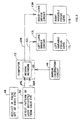
- FIG. 3 is a block diagram showing the operation of the system of FIG. 1.
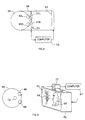
- FIG. 4 is a schematic diagram of an embodiment of an image-focusing system according to the present invention that is included in a three-dimensional virtual reality system.
- FIG. 5 is a schematic diagram of an embodiment of an image-focussing system according to the present invention that is used with a monitor that simultaneously displays different features with different degrees of focus as though they were at different distances from a person viewing the monitor.
- FIG. 6 is a schematic diagram of an embodiment of an image-focussing system according to the present invention that is used with a remotely controlled device that produces and transmits to a display monitor images of features at which a person viewing the monitor is gazing.
- FIG. 7 is a schematic diagram of an embodiment of an image-focussing system according to the present invention, wherein the variable focus means are embodied in a camera to provide at the focal plane of the camera a focussed image of a feature at which a person is gazing through a view finder of the camera.
- a preferred embodiment of a system includes eyeglasses 10 having a pair of variable-focus lenses 11, a computer 12, variable-focus-lens driver circuits 13, an IR (infrared light) source circuit 14, an IR detector circuit 15, a first bundle of optical fibers 16 and a second bundle of optical fibers 18.
- the eyeglasses 10 are disposed on a person 20 in such a correlation to a person's eyes 22L, 22R as to affect the person's perceived focus of images.
- Each of the variable-focus lenses 11 is a nematic liquid crystal display device.
- the conductive plates of the liquid crystal display device are connected to the variable-focus-lens driver circuits 13 by wires 24 extending through a stem 26 of the eyeglasses 10 from electrical contacts (not shown) disposed in the portions of the eyeglasses frame 28 that surround the lenses 12 to selectively apply appropriate control voltages to the respective conductive plates of the liquid crystal display devices.
- the first bundle of optical fibers 16 extend from the IR source circuit 14 into and through a stem 26 of the eyeglasses 10 and terminate in a pair of left and right fiber-optic transmitter arrays 30L, 30R respectively disposed in the portions of the eyeglasses frame 28 that surround the left variable-focus lens 11L and the right variable-focus lens 11R, as shown in FIG. 2.
- the second bundle of optical fibers 18 originate in a pair of left and right fiber-optic detector arrays 32L, 32R alternately disposed with the optical fibers of the respective fiber-optic transmitter arrays 30L, 30R in the portions of the eyeglasses frame 28 that surround the left variable-focus lens 11L and the right variable-focus lens 11R and extend through and out of the stem 26 of the eyeglasses 10 to the IR detector circuit 15.
- the numbers of optical fibers in each of the respective fiber-optic transmitter arrays 30L, 30R and fiber-optic detector arrays 32L, 32R preferably are more than as shown in FIG. 2.
- the spatial relationship of a person's eyes 22L, 22R varies as the person 20 gazes at various features 34, 35, 36, 37 (FIG. 1) that are located at different distances and at different angles from the person's eyes 22L, 22R. For example, when tile feature 36 at which the person is gazing is closer to the person's eyes 22L, 22R than a more distant feature 37, the pupils 38 of the person's eyes 22L, 22R are closer together than they would be if the person 20 were to gaze at the more distant feature 37.
- the IR detector circuit 15 provides data 40 indicating the disposition of each of the person's eyes 22L, 22R, and thereby the spatial relationship of the person's eyes 22L, 22R to the computer 12 in response to detecting light reflected by the person's eyes 22L, 22R; and the computer 12 provides focus-control signals 42 to the variable-focus-lens driver circuits 13 in response to processing such data 40 to thereby regulate the variable-focus lens 11L, 11R in accordance with the indicated spatial relationship.
- FIG. 3 The operation of a preferred embodiment of the system of FIG. 1 is described with reference to FIG. 3, in which (a) the computer 12 includes a neural network 44; and (b) a manual calibration circuit 46 is connected to the computer 12.
- an IR pulse is provided from the IR source circuit 14 through only one optical fiber 30L, 30R at a time in each of the respective left and right fiber-optic transmitter arrays 30L, 30R to provide a pair of light pulses that are respectively and simultaneously reflected off of the person's left and right eyes 22L, 22R and detected as a second step 50 by the IR detector circuit 15 from all of the optical fibers in the respective left and right fiber-optic detector arrays 32L, 32R.
- the series of the first and second steps 48 and 50 is continuously repeated with the light pulses being provided from a different optical fiber 30L, 30R of each of the respective left and right fiber-optic transmitter arrays 30L, 30R during each series to provide repetitive sequences of the series of first and second steps 48, 50 in which a light pulse is provided from each optical fiber 30L, 30R of each of the left and right fiber-optic transmitter arrays 30L, 30R and detected by the respective left and right fiber-optic detector arrays 32L, 32R.
- the light patterns detected by the combination of the left and right fiber-optic detector arrays 32L, 32R indicate the relative disposition of the pupils 38 of the person's left and right eyes 22L, 22R.
- the IR detector circuit 15 responds to the combination of light patterns detected during each sequence of the series of first and second steps 48, 50 by providing to the computer 12 disposition data 40L indicating the disposition of the left eye 22L and disposition data 40R indicating the disposition of the right eye 22R.
- the combined disposition data 40L, 40R indicates the spatial relationship of the person's eyes 22L, 22R both with respect to each other and with respect to the eyeglasses 10 with which the person 20 is gazing.
- the neural network 44 in the computer 12 processes the disposition data 40L, 40R to provide a left focus-control signal 42L for setting the focus of the left variable-focus lens 11L and a right focus-control signal 42R for setting the focus of the left variable-focus lens 11R in accordance with the spatial relationship between the left eye 22L and the right eye 22R indicated by the combined disposition data 40L, 40R for both eyes.
- the left-lens driver circuit 13L and the right-lens driver circuit 13R apply voltages to the plates of the liquid crystal displays of the left-variable focus lens 11L and the right variable-focus lens 11R in accordance with the respective left and right focus-control signals 42L, 42R to thereby focus the left variable-focus lens 11L and the right variable-focus lens 11R to cause the person 20 to sense an at least partially in-focus image of the feature 36, which is located at the vertex of the directions-of-sight-convergence angle for the person's eyes 22L, 22R.
- the neural network 44 Prior to using the eyeglasses 10, the neural network 44 is calibrated to cause the person to sense an at least partially in-focus image of a feature at a given location with respect to the person's eyes when the person's eyes have a given relative disposition. Such calibration is effected through use of the manual calibration circuit 46, which the person wearing the eyeglasses 10 operates to cause the neural network 44 to provide combinations of a left focus-control signal 42L and a right focus-control signal 42R that so set the left variable-focus lens 11L and the right variable-focus lens 11R respectively as to cause the person 20 to sense an at least partially in-focus image of a plurality of different features 34, 35, 36, 37 at different given locations with respect to the person's eyes 22L. 22R when the person's eyes have different given relative dispositions as indicated by the eye disposition data 40L. 40R for both eyes when the person 20 gazes at the respective different features 34, 35, 36, 37 at the different locations.
- the computer 12 processes the combined disposition data 40L. 40R for both eyes to measure a given parameter of the relative disposition of the person's eyes 22L, 22R, such as the distance between the pupils 38 of the person's eyes and regulates the focus of the variable-focus lens 11L, 11R by providing the left and right focus-control signals 42L, 42R to the left-lens driver circuit 13L and the right-lens driver circuit 13R from a look-up table in the computer 12 in accordance with the parameter measurement to thereby set the left and right variable-focus lenses 11L, 11R at one of a plurality of different predetermined focus settings in accordance with the spatial relationship between the person's eyes 22L, 22R indicated by the parameter measurement.
- a given parameter of the relative disposition of the person's eyes 22L, 22R such as the distance between the pupils 38 of the person's eyes and regulates the focus of the variable-focus lens 11L, 11R by providing the left and right focus-control signals 42L, 42R to the left-lens driver circuit 13L
- the look-up table is prepared by a calibration procedure in which the person wearing the eyeglasses 10 operates a manual calibration circuit to store in the look-up table such combinations of a left focus-control signal 42L and a right focus-control signal 42R as set the left variable-focus lens 11L and the right variable-focus lens 11R respectively as to cause the person 20 to sense an at least partially in-focus image of a plurality of different features 34, 35, 36, 37 at different given locations with respect to the person's eyes 22L. 22R in accordance with the different parameter measurements made when the person 20 gazes at the respective different features 34, 35, 36, 37 at the different locations.
- an embodiment of an image focussing system is included a three-dimensional virtual reality system that includes a computer 52 for generating left-eye-image components and right-eye-image components, a display screen 53 for displaying the computer-generated image components and goggles 54 for enabling a person 55 gazing at the display screen 53 through the goggles 54 to view three-dimensional images having virtual features that respectively appear to be at different distances from the person 55.
- the lenses 57L, 57R of the goggles 54 are nematic liquid crystal display devices such as included in the eyeglasses 10 in the embodiment described above with reference to FIGS.
- lens driver circuits are connected to the conductive plates of such liquid crystal display devices by wires extending through the frame 58 of the goggles 54 in order to selectively apply appropriate control voltages to the respective conductive plates of the liquid crystal display devices.
- control voltages are so applied as to cause the nematic liquid crystals to align to form an array of vertical shutters that are selectively disposed within each lens 57L, 57R so that the left lens 57L of the goggles 54 is adapted to shutter the displayed right-eye-image components from view by the person's left eye 60L and the right lens 57R is adapted to shutter the displayed left-eye-image components from view by the person's right eye 60R in order to provide a three-dimensional image to the person wearing the goggles 54.
- the displayed positions of the left-eye image components may be periodically interchanged with the displayed positions of the right-eye image components, with the shutters being changed when the displayed positions of the image components are interchanged so that each eye views an image having twice the resolution as would otherwise be provided.
- a pair of left and right fiber-optic transmitter arrays are respectively disposed in the portions of the goggles frame 58 that surround the left lens 57L and the right lens 57R; and a pair of left and right fiber-optic detector arrays (not shown) are alternately disposed with the optical fibers of the respective fiber-optic transmitter arrays in the portions of the goggles frame 58 that surround the left lens 57L and the right lens 57R, with such arrays being so disposed in the same manner as the like arrays are disposed in the eyeglasses frame 28, as shown in FIG. 2.
- An IR source circuit (not shown) is coupled by a bundle of optical fibers to the pair of left and right fiber-optic transmitter arrays; and an IR detector circuit (not shown) is coupled by another bundle of optical fibers to the pair of left and right fiber-optic detector arrays in the same manner as described above with reference to FIGS. 1 and 2.
- the IR detector circuit provides data indicating the disposition of each of the person's eyes 60L, 60R, and thereby the spatial relationship of the person's eyes 60L, 60R to the computer 52 in response to detecting light reflected by the person's eyes 60L, 60R in the same manner as described above with reference to FIGS 1-3.
- the computer 52 responds to the eye disposition data received from the IR detector circuit by providing lens control signals to the lens driver circuits in accordance with the lateral location of the virtual feature at which the person 55 wearing the goggles 54 is gazing so as to cause the lens driver circuits to so set the positions of the shutter arrays provided within the respective left and right lenses 57L, 57R that a three-dimensional image-is provided to the person wearing the goggles 54.
- the computer 52 regulates the focus of the virtual features displayed by the monitor 53 as perceived by the person 55 wearing the goggles 54, with such regulation being effected by the compositions of the respective left-eye-image components and right-eye-image components generated by the computer 52.
- the computer 52 responds to the eye disposition data received from the IR detector circuit by generating respective left-eye-image components and right-eye-image components that cause the monitor 53 to display an at least partially in-focus image of the virtual feature at which the person 55 wearing the goggles 54 is gazing, as perceived by the person 55 wearing the goggles 54, in accordance with the spatial relationship of the person's eyes 60L, 60R indicated by the eye disposition data.
- the lenses 57L, 57R of the goggles 54 are variable focus lenses, such as the lenses 11L, 11R included in eyeglasses 10 described with reference to FIGS. 1-3.
- the control signals provided by the computer 52 to the lens driver circuits also include focus-control components that are provided by the computer 52 in response to the eye disposition data received from the IR detector circuit to thereby regulate the variable-focus lenses 57L, 57R to cause the person 55 wearing the goggles 54 to perceive an at least partially in-focus image of the virtual feature at which the person 55 is gazing in accordance with the spatial relationship of the person's eyes 60L, 60R indicated by the eye disposition data.
- the computer 52 includes a neural network and a calibration circuit is connected to the computer 52 as described above for the eyeglasses embodiment with reference to FIG. 3.
- an embodiment of an image focussing system is used with a display monitor 62 having a screen 63 that perceptually simultaneously displays different features 64, 65 with different degrees of focus as though they were at different distances from a person 66 viewing the monitor 62 to thereby provide an image that is perceived by the person 66 as a three-dimensional image.
- one feature 64 is a tree and another feature 65 is a bear that appears to be at a greater distance than the tree 64 from the person 66 viewing the monitor 62.
- the focus of the respective displayed features 64, 65 is regulated by a computer 67 that controls the generation of the image displayed by the monitor 62.
- the displayed image of the tree 64 is not in focus and the displayed image of the bear 55 is in focus.
- the displayed image does not necessarily include both a left-eye image component and a right-eye image component, and in one embodiment it does not.
- An alternative embodiment of a three-dimensional display system that does not require special glasses for viewing displayed images that do include both a left-eye image component and a right-eye image component is described in International Publication No. WO 95/05052.
- an IR source 69 and a video camera 70 are disposed adjacent the display screen 63 of the monitor 62 and an IR reflector 72 is temporarily disposed on the forehead of the person 66.
- IR light directed from the IR source 69 toward the person 66 is-reflected from the eyes 68 of the person 66 and the IR reflector 72 and detected by the video camera 70.
- Eye disposition data signals indicating the spatial disposition of the eyes 68 of the person 66 are provided to the computer 67 in response to the reflected IR light detected by the video camera 70.
- an indication of the spatial relationship of the person's eyes 68 is provided by utilizing fiber-optic transmitter arrays and fiber-optic detector arrays disposed in the frames of glasses (not shown) to provide eye disposition data signals in the same manner as in the eyeglasses embodiment described above with reference to FIGS. 1-3.
- the lenses of the glasses are not variable-focus lenses, but rather are glass or plastic lenses shaped in accordance with the prescription for glasses normally worn by the person. If the person does not wear glasses, the lenses may be omitted from the frames, or clear glass or plastic may be inserted therein.
- the lenses of the glasses may include liquid crystal shutters for alternate viewing of left-and-right-eye images.
- the computer 67 regulates the respective focus of the displayed features 64, 65 by so responding to the eye disposition data as to cause the display monitor 62 to display an at least partially in-focus image of the feature 64, 65 at which the person is gazing in accordance with the spatial relationship of the person's eyes 68 indicated by the eye disposition data.
- an embodiment of an image focussing system is used with a remotely controlled device 75 that produces and transmits to a display monitor 76, such as a television monitor, an image signal for causing the monitor 76 to display an image that a person 78 viewing the monitor 76 through 3D-TV-viewing glasses 79 perceives as three dimensional.
- the 3D-TV-viewing glasses 79 may be of the well-known type in which one lens includes a red filter and the other lens includes a blue filter.
- the respective focus of the various features 81 included within the displayed image is regulated by a computer 80.
- the remotely controlled device 75 is mobile and the computer 80 is contained within the remotely controlled device 75.
- the remotely controlled device 75 includes a left variable-focus lens 82L and a right variable-focus lens 82R, wherein the respective focus of each lens 82L, 82R is controlled by the computer 80.
- the images respectively produced by the left variable-focus lens 82L and the right variable-focus lens 82R are processed electronically by the computer 80 to produce the image signal that is transmitted to the display monitor 75 by the remotely controlled device 75.
- An indication of the spatial relationship of the person's eyes 83 is provided by utilizing fiber-optic transmitter arrays (not shown) and fiber-optic detector arrays (not shown) disposed in the frames of the 3D-TV-viewing glasses 79 to provide eye disposition data signals in the same manner as in the eyeglasses embodiment described above with reference to FIGS. 1-3.
- the lenses of the 3D-TV-viewing glasses 79 are not variable-focus lenses.
- the person 78 views the displayed image through glasses such as those used in the above-described alternative embodiment of the system of FIG. 5, in which an indication of the spatial relationship of the person's eyes 83 is provided by utilizing fiber-optic transmitter arrays and fiber-optic detector arrays disposed in the frames of glasses to provide eye disposition data signals indicating the spatial disposition of the viewer's eyes 92 in the same manner as in the eyeglasses embodiment described above with reference to FIGS. 1-3.
- the lenses of the glasses are glass or plastic lenses shaped in accordance with the prescription for glasses normally worn by the person; and if the person does not wear glasses, the lenses may be omitted from the frames, or clear glass or plastic may be inserted therein.
- the computer 80 responds to the eye disposition data by regulating the setting of the variable focus lenses 82L, 82R of the remotely controlled device 75 so that the image signal produced by the computer 80 upon processing the images respectively produced by the variable focus lenses 82L, 82R causes the display monitor 75 to display an image in which the feature 77 at which the person 78 is gazing is at least partially in focus as perceived by the person 78.
- the computer 80 also responds to the eye disposition data by causing the mobile remotely controlled device 75 to move toward or away from the feature 81 at which the person 78 wearing the glasses 79 is gazing by whatever distance is necessary to enable an at least partially in-focus image of the feature 81 to be provided by regulating the setting of the variable-focus lenses 82L, 82R as described above.
- an image focussing system is used in a camera 86 having a variable focus lens 87.
- the setting of the variable focus lens 87 is regulated by a computer 88 contained within the camera 86.
- film disposed at the focal plane of the camera is exposed to an image being viewed by a person 90 through a view finder 91 of the camera 86.
- the view finder 91 enables the image viewed therethrough to be viewed by both eyes 92 of the person 90.
- a hood 93 is disposed around the view finder 91 so that the eyes 92 of the person 90 can be maintained in a constant position in relation to the view finder 91 by resting the hood 93 against the person's head about the eyes 92; and fiber-optic transmitter arrays (not shown) and fiber-optic detector arrays (not shown) are disposed within the hood 93 around the view finder 91 in order to provide eye disposition data signals indicating the spatial disposition of the viewer's eyes 92 in generally the same manner as in the eyeglasses embodiment described above with reference to FIGS. 1-3.
- the computer 88 responds to the eye disposition data signals by so regulating the focus of the variable focus lens 87 that an at least partially in-focus image of a feature 95 at which the person 90 is gazing through a view finder 91 of the camera.
- 86 is provided at the focal plane of the camera 86.
- data indicating the dispositions of the person's eyes may be provided by detecting sound waves, electromagnetic radiation, magnetic attraction, gravitational attraction, inductance and/or capacitance instead of, or in addition to, detecting reflected light;
- the means for reflecting light directed toward the eye may include contact lenses, ocular contact means, intraocular lenses and/or eye inserts instead of, or in addition to, the person's eyes;
- data indicating the dispositions of the person's eyes may be communicated from the detection means by sound waves and/or electromagnetic radiation, such as light or microwave, instead of, or in addition to wire;
- communication of the focus-control signals may be communicated by sound waves and/or electromagnetic radiation, such as light or microwave, instead of, or in addition to wire; and
- the variable-focus lenses may be embodied in binoculars and microscopes adapted for sensing three-dimensional images.
Landscapes
- Health & Medical Sciences (AREA)
- Ophthalmology & Optometry (AREA)
- Physics & Mathematics (AREA)
- General Health & Medical Sciences (AREA)
- General Physics & Mathematics (AREA)
- Optics & Photonics (AREA)
- Engineering & Computer Science (AREA)
- Multimedia (AREA)
- Signal Processing (AREA)
- Testing, Inspecting, Measuring Of Stereoscopic Televisions And Televisions (AREA)
- Liquid Crystal (AREA)
Claims (22)
- System zur Gewinnung einer zumindest teilweise scharfen Darstellung eines von einer Person betrachteten Objekts mitvariablen Fokussiereinrichtungen (11L, 11R, 57, 62, 82) zur Darstellung eines Abbilds des Objekts auf einem Bildschirm (53, 63);Einrichtungen (15, 50) zum Anzeigen eines räumlichen Verhältnisses zwischen den Augen der Person; undEinrichtungen (12, 13, 44, 52, 67, 80) zum Regulieren der variablen Fokussiereinrichtungen entsprechend dem angezeigten Verhältnis.
- System nach Anspruch 1, wobei die variablen Fokussiereinrichtungen und die Reguliereinrichtungen einen Computer (52, 67, 80) umfassen, der entsprechend dem angezeigten Verhältnis Bildkomponenten für das linke und für das rechte Auge generiert, und mit einem Bildschirm (53, 63) zur Darstellung der vom Computer generierten Bildkomponenten.
- System nach Anspruch 2, mit einer Brille (54), die es einer durch die Brille auf den Bildschirm (53) schauenden Person (55) ermöglicht, Darstellungen von Objekten zu sehen, die von der Person jeweils unterschiedlich weit weg zu sein scheinen.
- System nach Anspruch 2, das in einem System zur dreidimensionalen Darstellung von virtueller Realität enthalten ist, welches mittels einer Brille (54) es einer durch die Brille auf den Bildschirm (53) schauenden Person (55) ermöglicht, dreidimensionale Darstellungen von virtuellen Objekten so zu sehen, daß sie von der Person unterschiedlich weit weg zu sein scheinen.
- System nach Anspruch 1, wobei die variablen Fokussiereinrichtungen durch einen Monitor (62) verwirklicht werden, der anscheinend gleichzeitig verschiedene Objekte (64, 65) auf dem Bildschirm (63) mit unterschiedlichem Schärfegrad darstellt, so als ob sie sich in unterschiedlicher Entfernung von der auf den Monitor schauenden Person (66) befänden.
- System nach Anspruch 5, wobei die variablen Fokussiereinrichtungen so reguliert werden, daß sie eine zumindest teilweise scharfe Darstellung des von der Person betrachteten Objekts erzeugen.
- System nach Anspruch 1, wobei die Anzeigeeinrichtungen enthalten:Einrichtungen (15, 50) zum Bereitstellen von Daten (40, 40L, 40R), die die Position jedes Auges anzeigen; undEinrichtungen (12, 52, 67, 80), die die Positionsdaten kombinieren, um einen Wert über das relative räumliche Verhältnis der Augen der Person zu erhalten.
- System nach Anspruch 1, wobei die Anzeigeeinrichtungen Einrichtungen (15, 50) zum Bereitstellen von Daten (40, 40L, 40R) beinhaltet, die die Position jedes Auges anzeigen; und
wobei die Regulierungseinrichtungen ein neuronales Netz (44) zum Verarbeiten der Positionsdaten beinhalten, um Steuersignale zum Einstellen der Bildschärfe der variablen Fokussiereinrichtungen zu erhalten. - System nach Anspruch 1, wobei die variablen Fokussiereinrichtungen (82) durch eine ferngesteuerte Einrichtung (75) verwirklicht werden, die ein Signal erzeugt und an einen Monitor (76) überträgt, das eine zumindest teilweise scharfe Darstellung des Objekts auf dem Monitor bewirkt, das eine auf den Monitor schauende Person betrachtet.
- System nach einem der vorherigen Ansprüche, wobei die Anzeigeeinrichtungen das räumliche Verhältnis der Augen der Person zueinander anzeigen.
- Verfahren zur Gewinnung einer zumindest teilweise scharfen Darstellung eines von einer Person betrachteten Objekts mit den Schritten:(a) Darstellung eines Abbilds des Objekts auf einem Bildschirm (53, 63) unter Benutzung von variablen Fokussiereinrichtungen (11L, 11R, 57, 62, 82);(b) Anzeigen des räumlichen Verhältnisses zwischen den Augen der Person; und(c) Regulieren der variablen Fokussiereinrichtungen entsprechend dem angezeigten Verhältnis.
- Verfahren nach Anspruch 11 mit dem Schritt:(d) Anordnen der variablen Fokussiereinrichtungen in einem solchen Verhältnis zu den Augen der Person, dass der von der Person wahrgenommene Schärfegrad der Darstellungen beeinflusst wird.
- Verfahren nach Anspruch 11, wobei Schritt (b) folgende Schritte enthält:(d) Bereitstellung von Daten (40, 40L, 40R), die die Position jedes Auges anzeigen; und(e) Kombinieren der Positionsdaten, um einen Wert über das relative räumliche Verhältnis der Augen der Person zueinander zu erhalten.
- Verfahren nach Anspruch 11, wobei Schritt (b) folgenden Schritt enthält:(d) Bereitstellen von Daten (40, 40L, 40R), die die Position jedes Auges anzeigen; und wobei Schritt (c) folgenden Schritt enthält;(e) Verarbeiten der Positionsdaten in einem neuronalen Netz (44), um Steuersignale für die Fokussierung der variablen Fokussiereinrichtungen zu erhalten.
- Verfahren nach Anspruch 11, wobei Schritt (c) folgende Schritte enthält:(d) Bereitstellen von Steuersignalen für die Fokussierung (42, 42L, 42R) gemäß dem angezeigten Verhältnis; und(e) Fokussieren der variablen Fokussiereinrichtungen gemäß den Steuersignalen für die Fokussierung, um zu erreichen, dass die Person die mindestens teilweise scharfe Darstellung des Objekts wahrnimmt.
- Verfahren nach Anspruch 11 mit dem Schritt:(d) Kalibrieren der Reguliereinrichtungen (12, 52) um zu bewirken, dass die Person eine zumindest teilweise scharfe Darstellung eines Objekts wahrnimmt, wobei sich das Objekt in Bezug auf die Augen der Person an einem bestimmten Ort befindet, wenn sich die Augen der Person in einer bestimmten relativen Position befinden.
- Verfahren nach Anspruch 11, wobei die Schritte (a) und (c) folgende Schritte enthalten:(d) Erzeugen von Komponenten des vom linken Auge wahrgenommenen Bildes und von Komponenten des vom rechten Auge wahrgenommenen Bildes gemäß dem angezeigten Verhältnis; und(e) Anzeigen der vom Computer erzeugten Bildkomponenten.
- Verfahren nach Anspruch 17 mit dem Schritt:(f) Schauen auf den Bildschirm (53) durch eine Brille (54), um Darstellungen von Objekten zu sehen, die von einer auf den Bildschirm schauenden Person (55) jeweils unterschiedlich weit weg zu sein scheinen.
- Verfahren nach Anspruch 17 mit dem Schritt:(f) Schauen auf den Bildschirm (53) durch eine Brille (54), um dreidimensionale Darstellungen von virtuellen Objekten zu sehen, die von einer auf den Bildschirm schauenden Person (55) jeweils unterschiedlich weit weg zu sein scheinen.
- Verfahren nach Anspruch 11, wobei die Schritte (a) und (c) folgende Schritte enthalten:(d) anscheinend gleichzeitiges Anzeigen verschiedener Objekte (64, 65) mit unterschiedlichem Schärfegrad, so als ob diese sich von einer auf den Bildschirm schauenden Person (66) unterschiedlich weit weg befänden.
- Verfahren nach Anspruch 20, wobei Schritt (d) den Schritt enthält:(e) Anzeigen einer zumindest teilweise scharfen Darstellung des von der Person betrachteten Objekts.
- Verfahren nach einem der Ansprüche 11 bis 21, wobei Schritt (b) den Schritt enthält:(g) Anzeigen des räumlichen Verhältnisses der Augen der Person zueinander.
Applications Claiming Priority (2)
| Application Number | Priority Date | Filing Date | Title |
|---|---|---|---|
| US68801296A | 1996-07-26 | 1996-07-26 | |
| US688012 | 2000-10-13 |
Publications (3)
| Publication Number | Publication Date |
|---|---|
| EP0837603A2 EP0837603A2 (de) | 1998-04-22 |
| EP0837603A3 EP0837603A3 (de) | 1998-09-02 |
| EP0837603B1 true EP0837603B1 (de) | 2002-01-23 |
Family
ID=24762752
Family Applications (1)
| Application Number | Title | Priority Date | Filing Date |
|---|---|---|---|
| EP97305315A Expired - Lifetime EP0837603B1 (de) | 1996-07-26 | 1997-07-16 | System zum Steuern der Fokusierung von Linsen mit einer variablen Fokusierung mittels einer Detektion der räumlichen Beziehung der Augen einer Person |
Country Status (5)
| Country | Link |
|---|---|
| US (1) | US5861936A (de) |
| EP (1) | EP0837603B1 (de) |
| JP (1) | JPH10232364A (de) |
| DE (1) | DE69710017T2 (de) |
| ES (1) | ES2170919T3 (de) |
Families Citing this family (126)
| Publication number | Priority date | Publication date | Assignee | Title |
|---|---|---|---|---|
| USRE39539E1 (en) | 1996-08-19 | 2007-04-03 | Torch William C | System and method for monitoring eye movement |
| US6888590B1 (en) * | 1997-06-10 | 2005-05-03 | Olympus Optical Co., Ltd. | Optical elements (such as vari focal lens component, vari-focal diffractive optical element and variable declination prism) and electronic image pickup unit using optical elements |
| US6791599B1 (en) * | 1997-09-19 | 2004-09-14 | Sanyo Electric Co., Ltd. | Apparatus for driving liquid crystal shutter glasses and spatial transmission signal transmitting apparatus for liquid crystal shutter glasses |
| US6318857B1 (en) * | 1998-12-09 | 2001-11-20 | Asahi Kogaku Kogyo Kabushiki Kaisha | Variable power spectacles |
| US7023594B2 (en) * | 2000-06-23 | 2006-04-04 | E-Vision, Llc | Electro-optic lens with integrated components |
| US6986579B2 (en) * | 1999-07-02 | 2006-01-17 | E-Vision, Llc | Method of manufacturing an electro-active lens |
| US6491394B1 (en) | 1999-07-02 | 2002-12-10 | E-Vision, Llc | Method for refracting and dispensing electro-active spectacles |
| US6491391B1 (en) | 1999-07-02 | 2002-12-10 | E-Vision Llc | System, apparatus, and method for reducing birefringence |
| US6619799B1 (en) * | 1999-07-02 | 2003-09-16 | E-Vision, Llc | Optical lens system with electro-active lens having alterably different focal lengths |
| US6517203B1 (en) | 1999-07-02 | 2003-02-11 | E-Vision, Llc | System, apparatus, and method for correcting vision using electro-active spectacles |
| US6733130B2 (en) | 1999-07-02 | 2004-05-11 | E-Vision, Llc | Method for refracting and dispensing electro-active spectacles |
| US6857741B2 (en) * | 2002-01-16 | 2005-02-22 | E-Vision, Llc | Electro-active multi-focal spectacle lens |
| US6871951B2 (en) * | 2000-06-23 | 2005-03-29 | E-Vision, Llc | Electro-optic lens with integrated components |
| US7290875B2 (en) * | 2004-11-02 | 2007-11-06 | Blum Ronald D | Electro-active spectacles and method of fabricating same |
| US7604349B2 (en) * | 1999-07-02 | 2009-10-20 | E-Vision, Llc | Static progressive surface region in optical communication with a dynamic optic |
| US7775660B2 (en) | 1999-07-02 | 2010-08-17 | E-Vision Llc | Electro-active ophthalmic lens having an optical power blending region |
| US7988286B2 (en) | 1999-07-02 | 2011-08-02 | E-Vision Llc | Static progressive surface region in optical communication with a dynamic optic |
| US20070258039A1 (en) * | 1999-07-02 | 2007-11-08 | Duston Dwight P | Spectacle frame bridge housing electronics for electro-active spectacle lenses |
| US7404636B2 (en) * | 1999-07-02 | 2008-07-29 | E-Vision, Llc | Electro-active spectacle employing modal liquid crystal lenses |
| US20090103044A1 (en) * | 1999-07-02 | 2009-04-23 | Duston Dwight P | Spectacle frame bridge housing electronics for electro-active spectacle lenses |
| US7290876B2 (en) * | 1999-07-02 | 2007-11-06 | E-Vision, Llc | Method and system for electro-active spectacle lens design |
| US6851805B2 (en) * | 1999-07-02 | 2005-02-08 | E-Vision, Llc | Stabilized electro-active contact lens |
| US7264354B2 (en) | 1999-07-02 | 2007-09-04 | E-Vision, Llc | Method and apparatus for correcting vision using an electro-active phoropter |
| DE10132378A1 (de) * | 2001-07-06 | 2003-04-24 | Zeiss Carl Meditec Ag | Verfahren und Vorrichtung zur Verfolgung von Augenbewegungen |
| KR20040053147A (ko) * | 2001-10-05 | 2004-06-23 | 이-비젼 엘엘씨 | 하이브리드 전기-활성 렌즈 |
| US20030210378A1 (en) * | 2002-01-17 | 2003-11-13 | Riza Nabeel Agha | Optoelectronic eye examination system |
| US20080106633A1 (en) * | 2002-03-13 | 2008-05-08 | Blum Ronald D | Electro-optic lens with integrated components for varying refractive properties |
| US7033025B2 (en) * | 2002-05-17 | 2006-04-25 | Virtocc, Inc. | Interactive occlusion system |
| DE10239689B4 (de) * | 2002-08-27 | 2006-02-02 | Bundesrepublik Deutschland, vertr. d. d. Bundesministerium für Wirtschaft und Arbeit, dieses vertr. d. d. Präsidenten der Physikalisch-Technischen Bundesanstalt | Verfahren zur Einstellung einer als Sehhilfe dienenden Linse und adaptive Linse einer Brille |
| DE10258729B4 (de) * | 2002-12-06 | 2008-04-03 | Carl Zeiss | Selbstfokussierende Brille und Verfahren zum Selbstfokussieren einer Brille |
| US20040174497A1 (en) * | 2003-03-07 | 2004-09-09 | Manish Sharma | Method and system for controlling the movement of a device |
| TW200532278A (en) * | 2003-08-15 | 2005-10-01 | E Vision Llc | Enhanced electro-active lens system |
| WO2005033782A2 (en) * | 2003-10-03 | 2005-04-14 | Invisia Ltd. | Multifocal lens |
| KR100533643B1 (ko) * | 2004-03-29 | 2005-12-06 | 삼성전기주식회사 | 가변 구형파 구동장치 |
| US20110077548A1 (en) * | 2004-04-01 | 2011-03-31 | Torch William C | Biosensors, communicators, and controllers monitoring eye movement and methods for using them |
| MXPA06011168A (es) * | 2004-04-01 | 2007-04-16 | William C Torch | Biosensores, comunicadores, y controladores que verifican el movimiento del ojo y metodos para utilizarlos. |
| US10039445B1 (en) | 2004-04-01 | 2018-08-07 | Google Llc | Biosensors, communicators, and controllers monitoring eye movement and methods for using them |
| US20050237485A1 (en) * | 2004-04-21 | 2005-10-27 | Blum Ronald D | Method and apparatus for correcting vision |
| US20060066808A1 (en) * | 2004-09-27 | 2006-03-30 | Blum Ronald D | Ophthalmic lenses incorporating a diffractive element |
| US8915588B2 (en) | 2004-11-02 | 2014-12-23 | E-Vision Smart Optics, Inc. | Eyewear including a heads up display |
| KR101244647B1 (ko) * | 2004-11-02 | 2013-03-18 | 이-비젼 엘엘씨 | 전기 활성 안경 및 이의 제조 방법 |
| US9801709B2 (en) | 2004-11-02 | 2017-10-31 | E-Vision Smart Optics, Inc. | Electro-active intraocular lenses |
| US8778022B2 (en) * | 2004-11-02 | 2014-07-15 | E-Vision Smart Optics Inc. | Electro-active intraocular lenses |
| US7656569B2 (en) * | 2004-12-03 | 2010-02-02 | Searete Llc | Vision modification with reflected image |
| US8244342B2 (en) * | 2004-12-03 | 2012-08-14 | The Invention Science Fund I, Llc | Method and system for adaptive vision modification |
| US9155483B2 (en) | 2004-12-03 | 2015-10-13 | The Invention Science Fund I, Llc | Vision modification with reflected image |
| US7344244B2 (en) * | 2004-12-03 | 2008-03-18 | Searete, Llc | Adjustable lens system with neural-based control |
| US7594727B2 (en) * | 2004-12-03 | 2009-09-29 | Searete Llc | Vision modification with reflected image |
| US7931373B2 (en) * | 2004-12-03 | 2011-04-26 | The Invention Science Fund I, Llc | Vision modification with reflected image |
| US7470027B2 (en) * | 2004-12-03 | 2008-12-30 | Searete Llc | Temporal vision modification |
| US7486988B2 (en) * | 2004-12-03 | 2009-02-03 | Searete Llc | Method and system for adaptive vision modification |
| US8104892B2 (en) * | 2004-12-03 | 2012-01-31 | The Invention Science Fund I, Llc | Vision modification with reflected image |
| US7334892B2 (en) * | 2004-12-03 | 2008-02-26 | Searete Llc | Method and system for vision enhancement |
| US7350919B2 (en) * | 2004-12-03 | 2008-04-01 | Searete Llc | Vision modification with reflected image |
| US7334894B2 (en) * | 2004-12-03 | 2008-02-26 | Searete, Llc | Temporal vision modification |
| US7390088B2 (en) * | 2004-12-03 | 2008-06-24 | Searete Llc | Adjustable lens system with neural-based control |
| US8885139B2 (en) * | 2005-01-21 | 2014-11-11 | Johnson & Johnson Vision Care | Adaptive electro-active lens with variable focal length |
| US8956396B1 (en) * | 2005-10-24 | 2015-02-17 | Lockheed Martin Corporation | Eye-tracking visual prosthetic and method |
| US20070159562A1 (en) * | 2006-01-10 | 2007-07-12 | Haddock Joshua N | Device and method for manufacturing an electro-active spectacle lens involving a mechanically flexible integration insert |
| US8668334B2 (en) * | 2006-02-27 | 2014-03-11 | Vital Art And Science Incorporated | Vision measurement and training system and method of operation thereof |
| US20080273166A1 (en) | 2007-05-04 | 2008-11-06 | William Kokonaski | Electronic eyeglass frame |
| WO2008105780A2 (en) | 2006-05-24 | 2008-09-04 | Pixeloptics, Inc. | Optical rangefinder for an electro-active lens |
| JP2009541793A (ja) * | 2006-06-23 | 2009-11-26 | ピクセルオプティクス, インコーポレイテッド | 電気活性眼鏡レンズ用の電子アダプタ |
| WO2008054654A2 (en) * | 2006-10-27 | 2008-05-08 | Pixeloptics, Inc. | Spectacle hinge for providing on off power |
| AR064985A1 (es) | 2007-01-22 | 2009-05-06 | E Vision Llc | Lente electroactivo flexible |
| US7926940B2 (en) | 2007-02-23 | 2011-04-19 | Pixeloptics, Inc. | Advanced electro-active optic device |
| AU2008218240B2 (en) * | 2007-02-23 | 2014-01-30 | E-Vision Smart Optics, Inc. | Ophthalmic dynamic aperture |
| US20090091818A1 (en) * | 2007-10-05 | 2009-04-09 | Haddock Joshua N | Electro-active insert |
| CA2679977A1 (en) | 2007-03-07 | 2008-09-18 | Pixeloptics, Inc. | Multifocal lens having a progressive optical power region and a discontinuity |
| US7883207B2 (en) | 2007-12-14 | 2011-02-08 | Pixeloptics, Inc. | Refractive-diffractive multifocal lens |
| US20080273169A1 (en) * | 2007-03-29 | 2008-11-06 | Blum Ronald D | Multifocal Lens Having a Progressive Optical Power Region and a Discontinuity |
| US10613355B2 (en) | 2007-05-04 | 2020-04-07 | E-Vision, Llc | Moisture-resistant eye wear |
| US11061252B2 (en) | 2007-05-04 | 2021-07-13 | E-Vision, Llc | Hinge for electronic spectacles |
| US12572035B2 (en) | 2007-05-04 | 2026-03-10 | E-Vision Optics, Llc | Moisture-resistant eye wear |
| US7784938B2 (en) * | 2007-05-09 | 2010-08-31 | Dolby Laboratories Licensing Corporation | Method and system for shaped glasses and viewing 3D images |
| US8317321B2 (en) | 2007-07-03 | 2012-11-27 | Pixeloptics, Inc. | Multifocal lens with a diffractive optical power region |
| US7806527B2 (en) * | 2007-08-16 | 2010-10-05 | Ross Colin A | Electromagnetic beam detection system |
| US8154804B2 (en) * | 2008-03-25 | 2012-04-10 | E-Vision Smart Optics, Inc. | Electro-optic lenses for correction of higher order aberrations |
| US8411214B2 (en) * | 2008-06-24 | 2013-04-02 | United States Of America As Represented By The Administrator Of The National Aeronautics And Space Administration | Variably transmittive, electronically-controlled eyewear |
| TWI387316B (zh) * | 2008-11-18 | 2013-02-21 | 財團法人工業技術研究院 | 立體影像顯示裝置與立體影像顯示方法 |
| US8398239B2 (en) * | 2009-03-02 | 2013-03-19 | Honeywell International Inc. | Wearable eye tracking system |
| DK2427095T3 (da) | 2009-05-09 | 2023-10-02 | Genentech Inc | System til vurdering og sporing af formforskelsvisning |
| WO2010144478A2 (en) * | 2009-06-08 | 2010-12-16 | Reald Inc. | Shutter-glass eyewear control |
| US8890946B2 (en) * | 2010-03-01 | 2014-11-18 | Eyefluence, Inc. | Systems and methods for spatially controlled scene illumination |
| US12436411B2 (en) | 2010-07-02 | 2025-10-07 | E-Vision Optics, Llc | Moisture-resistant eye wear |
| US8474976B2 (en) * | 2010-10-30 | 2013-07-02 | Thang Duong | Automatic accommodative spectacles using sensors and focusing elements |
| KR101670927B1 (ko) * | 2010-11-05 | 2016-11-01 | 삼성전자주식회사 | 디스플레이 장치 및 방법 |
| US8628193B2 (en) * | 2010-11-20 | 2014-01-14 | Yibin TIAN | Automatic accommodative spectacles using a scene analyzer and focusing elements |
| WO2012102706A1 (en) * | 2011-01-25 | 2012-08-02 | Hewlett-Packard Development Company L.P. | Three dimensional adjustable lenses |
| US12510773B2 (en) | 2011-02-11 | 2025-12-30 | E-Vision Optics, Llc | Moisture-resistant eye wear |
| EP2499964B1 (de) * | 2011-03-18 | 2015-04-15 | SensoMotoric Instruments Gesellschaft für innovative Sensorik mbH | Optische Messvorrichtung und System |
| KR101777875B1 (ko) * | 2011-04-28 | 2017-09-13 | 엘지디스플레이 주식회사 | 입체 영상 표시장치와 그 입체 영상 조절 방법 |
| US8911087B2 (en) | 2011-05-20 | 2014-12-16 | Eyefluence, Inc. | Systems and methods for measuring reactions of head, eyes, eyelids and pupils |
| US8885877B2 (en) | 2011-05-20 | 2014-11-11 | Eyefluence, Inc. | Systems and methods for identifying gaze tracking scene reference locations |
| US20130050448A1 (en) * | 2011-08-24 | 2013-02-28 | Ati Technologies Ulc | Method, circuitry and system for better integrating multiview-based 3d display technology with the human visual system |
| US8929589B2 (en) | 2011-11-07 | 2015-01-06 | Eyefluence, Inc. | Systems and methods for high-resolution gaze tracking |
| JP2013109010A (ja) * | 2011-11-17 | 2013-06-06 | Canon Inc | 立体映像撮影システム |
| WO2013103985A2 (en) | 2012-01-06 | 2013-07-11 | Pixeloptics, Inc. | Eyewear docking station and electronic module |
| CN104685409B (zh) | 2012-09-30 | 2017-08-29 | 奥普蒂卡阿姆卡(艾阿)有限公司 | 具有电可调谐功率和对准的透镜 |
| US11126040B2 (en) | 2012-09-30 | 2021-09-21 | Optica Amuka (A.A.) Ltd. | Electrically-tunable lenses and lens systems |
| US8888278B2 (en) * | 2013-02-08 | 2014-11-18 | Sony Dadc Austria Ag | Apparatus for eyesight enhancement, method for calibrating an apparatus and computer program |
| JP2014219659A (ja) | 2013-04-11 | 2014-11-20 | Jnc株式会社 | 剥離防止剤を含有した重合性液晶組成物を用いたフィルム |
| DE102013103801B4 (de) * | 2013-04-16 | 2024-01-04 | Carl Zeiss Ag | Vorrichtung und Verfahren zum Ermitteln einer Blickrichtung, elektronische Brille und Verfahren zum Steuern einer elektronischen Brille |
| JP6020923B2 (ja) * | 2013-05-21 | 2016-11-02 | パナソニックIpマネジメント株式会社 | 焦点可変レンズを有するビューア、および映像表示システム |
| JP2015052772A (ja) * | 2013-08-06 | 2015-03-19 | 孝郎 林 | 視力矯正装置 |
| CN104092935B (zh) * | 2014-06-05 | 2018-06-26 | 西安中兴新软件有限责任公司 | 一种图像拍摄的处理方法和装置 |
| WO2015186010A1 (en) * | 2014-06-05 | 2015-12-10 | Optica Amuka (A.A.) Ltd. | Control of dynamic lenses |
| WO2017079342A1 (en) | 2015-11-02 | 2017-05-11 | Focure, Inc. | Continuous autofocusing eyewear |
| US10281744B2 (en) | 2015-11-02 | 2019-05-07 | Focure Inc. | Continuous autofocusing eyewear using structured light |
| CN108605120A (zh) * | 2016-01-29 | 2018-09-28 | 惠普发展公司,有限责任合伙企业 | 基于关于显示器的眼调节的观看设备调整 |
| CA3019946C (en) | 2016-04-08 | 2023-02-28 | Magic Leap, Inc. | Augmented reality systems and methods with variable focus lens elements |
| ES2973138T3 (es) | 2016-04-12 | 2024-06-18 | E Vision Smart Optics Inc | Lentes electroactivas con puentes resistivos elevados |
| EP3446176B1 (de) | 2016-04-17 | 2021-11-24 | Optica Amuka (A.A.) Ltd. | Brille beinhaltend eine flüssigkristalllinse mit verbessertem elektrischem antrieb |
| US11360330B2 (en) | 2016-06-16 | 2022-06-14 | Optica Amuka (A.A.) Ltd. | Tunable lenses for spectacles |
| US11747619B2 (en) | 2017-07-10 | 2023-09-05 | Optica Amuka (A.A.) Ltd. | Virtual reality and augmented reality systems with dynamic vision correction |
| US11953764B2 (en) | 2017-07-10 | 2024-04-09 | Optica Amuka (A.A.) Ltd. | Tunable lenses with enhanced performance features |
| CN107272220B (zh) * | 2017-08-16 | 2019-11-19 | 北京五环伟业科技有限公司 | 眼镜系统 |
| WO2019069812A1 (ja) * | 2017-10-05 | 2019-04-11 | 株式会社ソニー・インタラクティブエンタテインメント | ヘッドマウントディスプレイの視線検出システム、ヘッドマウントディスプレイ及びヘッドマウントディスプレイの視線検出方法 |
| AU2018348229A1 (en) | 2017-10-11 | 2020-04-23 | Magic Leap, Inc. | Augmented reality display comprising eyepiece having a transparent emissive display |
| WO2019077442A1 (en) | 2017-10-16 | 2019-04-25 | Optica Amuka (A.A.) Ltd. | ELECTRICALLY ADJUSTABLE GLASS LENSES THAT CAN BE CONTROLLED BY AN EXTERNAL SYSTEM |
| WO2020245680A1 (en) | 2019-06-02 | 2020-12-10 | Optica Amuka (A.A.) Ltd. | Electrically-tunable vision aid for treatment of myopia |
| CN110464611A (zh) * | 2019-07-23 | 2019-11-19 | 苏州国科视清医疗科技有限公司 | 一种数字化弱视增强训练装置和系统及其相关算法 |
| WO2022270852A1 (ko) | 2021-06-22 | 2022-12-29 | 삼성전자 주식회사 | 가변 초점 렌즈를 포함하는 증강 현실 디바이스 및 그 동작 방법 |
| US12141998B2 (en) * | 2022-03-17 | 2024-11-12 | Motorola Mobility Llc | Electronic device with gaze-based autofocus of camera during video rendition of scene |
| US12022182B2 (en) | 2022-05-26 | 2024-06-25 | Motorola Mobility Llc | Visual feature based video effects |
| US12464088B2 (en) | 2023-08-02 | 2025-11-04 | Motorola Mobility Llc | Gaze-based video conference prompts |
Family Cites Families (20)
| Publication number | Priority date | Publication date | Assignee | Title |
|---|---|---|---|---|
| US4181408A (en) * | 1977-12-05 | 1980-01-01 | Senders John W | Vision compensation |
| US4300818A (en) * | 1978-03-13 | 1981-11-17 | Schachar Ronald A | Multifocal ophthalmic lens |
| EP0066547A3 (de) * | 1981-06-02 | 1985-10-09 | Schweizerische Aluminium Ag | Servierwagen |
| JPH0685590B2 (ja) * | 1985-11-15 | 1994-10-26 | 株式会社日立製作所 | 立体表示システム |
| IT1190508B (it) * | 1986-03-24 | 1988-02-16 | Daniele Senatore | Occhiali a trasparenza regolabile |
| JP3016249B2 (ja) * | 1988-04-30 | 2000-03-06 | オリンパス光学工業株式会社 | 立体メガネ装置 |
| JPH0336678A (ja) * | 1989-07-04 | 1991-02-18 | Fujitsu Ltd | 遠近感強調表示装置 |
| JPH03292093A (ja) * | 1990-04-10 | 1991-12-24 | Seiko Epson Corp | 3次元表示装置 |
| JPH05211625A (ja) * | 1991-11-06 | 1993-08-20 | Canon Inc | 撮像装置 |
| JP3318680B2 (ja) * | 1992-04-28 | 2002-08-26 | サン・マイクロシステムズ・インコーポレーテッド | 画像生成方法及び画像生成装置 |
| US5309185A (en) * | 1992-06-08 | 1994-05-03 | Harper Gilberto B | Apparatus and method for objective quantitative assessment of human ocular coordination |
| JPH08104B2 (ja) * | 1992-09-17 | 1996-01-10 | 株式会社エイ・ティ・アール視聴覚機構研究所 | 奥行き視線移動検査装置 |
| JPH074343B2 (ja) * | 1992-09-29 | 1995-01-25 | 株式会社エイ・ティ・アール視聴覚機構研究所 | 奥行き知覚分析装置 |
| US5359444A (en) * | 1992-12-24 | 1994-10-25 | Motorola, Inc. | Auto-focusing optical apparatus |
| WO1995005052A1 (en) * | 1993-08-09 | 1995-02-16 | Jens Ole Sorensen | Stereo-optic image display system with enhanced resolution |
| JPH07168082A (ja) * | 1993-12-16 | 1995-07-04 | Olympus Optical Co Ltd | 視線検出装置 |
| JP3143558B2 (ja) * | 1994-02-02 | 2001-03-07 | キヤノン株式会社 | 画像表示方法および装置 |
| US5410376A (en) * | 1994-02-04 | 1995-04-25 | Pulse Medical Instruments | Eye tracking method and apparatus |
| JP3387624B2 (ja) * | 1994-05-20 | 2003-03-17 | キヤノン株式会社 | 立体ディスプレイ装置 |
| JP2994960B2 (ja) * | 1994-06-17 | 1999-12-27 | 三洋電機株式会社 | 虚像式立体画像表示装置 |
-
1997
- 1997-07-11 US US08/893,788 patent/US5861936A/en not_active Expired - Lifetime
- 1997-07-16 EP EP97305315A patent/EP0837603B1/de not_active Expired - Lifetime
- 1997-07-16 DE DE69710017T patent/DE69710017T2/de not_active Expired - Fee Related
- 1997-07-16 ES ES97305315T patent/ES2170919T3/es not_active Expired - Lifetime
- 1997-07-25 JP JP9215950A patent/JPH10232364A/ja active Pending
Also Published As
| Publication number | Publication date |
|---|---|
| JPH10232364A (ja) | 1998-09-02 |
| DE69710017D1 (de) | 2002-03-14 |
| EP0837603A2 (de) | 1998-04-22 |
| EP0837603A3 (de) | 1998-09-02 |
| US5861936A (en) | 1999-01-19 |
| ES2170919T3 (es) | 2002-08-16 |
| DE69710017T2 (de) | 2002-10-10 |
Similar Documents
| Publication | Publication Date | Title |
|---|---|---|
| US5861936A (en) | Regulating focus in accordance with relationship of features of a person's eyes | |
| US11287663B2 (en) | Optical transmitting module and head mounted display device | |
| US5825456A (en) | Stereoscopic video display apparatus | |
| US6762794B1 (en) | Image pick-up apparatus for stereoscope | |
| US6864910B1 (en) | Optical apparatus | |
| US5864359A (en) | Stereoscopic autofocusing based on comparing the left and right eye images | |
| US7177083B2 (en) | Display device with electrooptical focussing | |
| JP3387624B2 (ja) | 立体ディスプレイ装置 | |
| EP0744036B1 (de) | Bildwiedergabevorrichtung | |
| US20190174124A1 (en) | Near-eye display system including a modulation stack | |
| JPH09505906A (ja) | ステレオスコープイメージ機構と視覚機構 | |
| KR20120105495A (ko) | 입체 영상 촬상 장치 | |
| CN108351515A (zh) | 眼睛投影系统和方法 | |
| JPH09322199A (ja) | 立体映像ディスプレイ装置 | |
| US20090059364A1 (en) | Systems and methods for electronic and virtual ocular devices | |
| US20190113758A1 (en) | Image displayable eyeglasses | |
| US20010010508A1 (en) | Apparatus and method for displaying stereoscopic images | |
| US20040070823A1 (en) | Head-mount recording of three-dimensional stereo video images | |
| EP0577268B1 (de) | Optisches System | |
| US4810057A (en) | Three-dimensional viewing glasses | |
| US20170212360A1 (en) | Glasses-free 3d display device | |
| JP4208351B2 (ja) | 撮像装置、輻輳距離決定方法および記憶媒体 | |
| US20150335241A1 (en) | Apparatus for obtaining status information of crystalline lens and equipment including the same | |
| JPH08191462A (ja) | 立体映像再生装置および立体撮影装置 | |
| KR100245332B1 (ko) | 헤드 마운트 디스플레이 |
Legal Events
| Date | Code | Title | Description |
|---|---|---|---|
| PUAI | Public reference made under article 153(3) epc to a published international application that has entered the european phase |
Free format text: ORIGINAL CODE: 0009012 |
|
| AK | Designated contracting states |
Kind code of ref document: A2 Designated state(s): DE ES FR GB IT |
|
| AX | Request for extension of the european patent |
Free format text: AL;LT;LV;RO;SI |
|
| RAP1 | Party data changed (applicant data changed or rights of an application transferred) |
Owner name: SORENSEN, JENS OLE |
|
| RIN1 | Information on inventor provided before grant (corrected) |
Inventor name: SORENSEN, JENS OLE |
|
| PUAL | Search report despatched |
Free format text: ORIGINAL CODE: 0009013 |
|
| AK | Designated contracting states |
Kind code of ref document: A3 Designated state(s): AT BE CH DE DK ES FI FR GB GR IE IT LI LU MC NL PT SE |
|
| AX | Request for extension of the european patent |
Free format text: AL;LT;LV;RO;SI |
|
| RAP1 | Party data changed (applicant data changed or rights of an application transferred) |
Owner name: GILLAN HOLDINGS LIMITED |
|
| RIN1 | Information on inventor provided before grant (corrected) |
Inventor name: SORENSEN, JENS OLE |
|
| 17P | Request for examination filed |
Effective date: 19990219 |
|
| AKX | Designation fees paid |
Free format text: DE ES FR GB IT |
|
| RBV | Designated contracting states (corrected) |
Designated state(s): DE ES FR GB IT |
|
| 17Q | First examination report despatched |
Effective date: 20000908 |
|
| GRAG | Despatch of communication of intention to grant |
Free format text: ORIGINAL CODE: EPIDOS AGRA |
|
| GRAG | Despatch of communication of intention to grant |
Free format text: ORIGINAL CODE: EPIDOS AGRA |
|
| GRAH | Despatch of communication of intention to grant a patent |
Free format text: ORIGINAL CODE: EPIDOS IGRA |
|
| GRAH | Despatch of communication of intention to grant a patent |
Free format text: ORIGINAL CODE: EPIDOS IGRA |
|
| GRAA | (expected) grant |
Free format text: ORIGINAL CODE: 0009210 |
|
| REG | Reference to a national code |
Ref country code: GB Ref legal event code: IF02 |
|
| AK | Designated contracting states |
Kind code of ref document: B1 Designated state(s): DE ES FR GB IT |
|
| REF | Corresponds to: |
Ref document number: 69710017 Country of ref document: DE Date of ref document: 20020314 |
|
| ET | Fr: translation filed | ||
| PGFP | Annual fee paid to national office [announced via postgrant information from national office to epo] |
Ref country code: ES Payment date: 20020709 Year of fee payment: 6 |
|
| REG | Reference to a national code |
Ref country code: ES Ref legal event code: FG2A Ref document number: 2170919 Country of ref document: ES Kind code of ref document: T3 |
|
| PLBE | No opposition filed within time limit |
Free format text: ORIGINAL CODE: 0009261 |
|
| STAA | Information on the status of an ep patent application or granted ep patent |
Free format text: STATUS: NO OPPOSITION FILED WITHIN TIME LIMIT |
|
| 26N | No opposition filed | ||
| PG25 | Lapsed in a contracting state [announced via postgrant information from national office to epo] |
Ref country code: ES Free format text: LAPSE BECAUSE OF NON-PAYMENT OF DUE FEES Effective date: 20030717 |
|
| REG | Reference to a national code |
Ref country code: GB Ref legal event code: 732E |
|
| REG | Reference to a national code |
Ref country code: FR Ref legal event code: TP |
|
| PGFP | Annual fee paid to national office [announced via postgrant information from national office to epo] |
Ref country code: GB Payment date: 20040611 Year of fee payment: 8 |
|
| PGFP | Annual fee paid to national office [announced via postgrant information from national office to epo] |
Ref country code: FR Payment date: 20040630 Year of fee payment: 8 |
|
| PGFP | Annual fee paid to national office [announced via postgrant information from national office to epo] |
Ref country code: DE Payment date: 20040929 Year of fee payment: 8 |
|
| REG | Reference to a national code |
Ref country code: ES Ref legal event code: FD2A Effective date: 20030717 |
|
| PG25 | Lapsed in a contracting state [announced via postgrant information from national office to epo] |
Ref country code: IT Free format text: LAPSE BECAUSE OF NON-PAYMENT OF DUE FEES Effective date: 20050716 Ref country code: GB Free format text: LAPSE BECAUSE OF NON-PAYMENT OF DUE FEES Effective date: 20050716 |
|
| PG25 | Lapsed in a contracting state [announced via postgrant information from national office to epo] |
Ref country code: DE Free format text: LAPSE BECAUSE OF NON-PAYMENT OF DUE FEES Effective date: 20060201 |
|
| GBPC | Gb: european patent ceased through non-payment of renewal fee |
Effective date: 20050716 |
|
| PG25 | Lapsed in a contracting state [announced via postgrant information from national office to epo] |
Ref country code: FR Free format text: LAPSE BECAUSE OF NON-PAYMENT OF DUE FEES Effective date: 20060331 |
|
| REG | Reference to a national code |
Ref country code: FR Ref legal event code: ST Effective date: 20060331 |