EP0838314B1 - Dispositif de manipulation et support pour machines de coupe - Google Patents
Dispositif de manipulation et support pour machines de coupe Download PDFInfo
- Publication number
- EP0838314B1 EP0838314B1 EP97118042A EP97118042A EP0838314B1 EP 0838314 B1 EP0838314 B1 EP 0838314B1 EP 97118042 A EP97118042 A EP 97118042A EP 97118042 A EP97118042 A EP 97118042A EP 0838314 B1 EP0838314 B1 EP 0838314B1
- Authority
- EP
- European Patent Office
- Prior art keywords
- elements
- comb
- laminations
- structure according
- base
- Prior art date
- Legal status (The legal status is an assumption and is not a legal conclusion. Google has not performed a legal analysis and makes no representation as to the accuracy of the status listed.)
- Expired - Lifetime
Links
- 238000005520 cutting process Methods 0.000 title claims abstract description 17
- 238000003475 lamination Methods 0.000 claims abstract description 30
- XLYOFNOQVPJJNP-UHFFFAOYSA-N water Substances O XLYOFNOQVPJJNP-UHFFFAOYSA-N 0.000 claims abstract description 18
- 229920002994 synthetic fiber Polymers 0.000 claims abstract description 4
- 230000002829 reductive effect Effects 0.000 claims abstract description 3
- 229910001220 stainless steel Inorganic materials 0.000 claims description 5
- 239000010935 stainless steel Substances 0.000 claims description 5
- 230000000295 complement effect Effects 0.000 claims description 3
- 238000007373 indentation Methods 0.000 claims description 3
- 239000000463 material Substances 0.000 claims description 3
- 239000002184 metal Substances 0.000 claims description 3
- 230000000750 progressive effect Effects 0.000 claims description 2
- 239000010985 leather Substances 0.000 description 19
- 230000002745 absorbent Effects 0.000 description 2
- 239000002250 absorbent Substances 0.000 description 2
- 230000000694 effects Effects 0.000 description 2
- 239000011358 absorbing material Substances 0.000 description 1
- 230000002411 adverse Effects 0.000 description 1
- 230000004888 barrier function Effects 0.000 description 1
- 238000010276 construction Methods 0.000 description 1
- 230000008878 coupling Effects 0.000 description 1
- 238000010168 coupling process Methods 0.000 description 1
- 238000005859 coupling reaction Methods 0.000 description 1
- 238000001035 drying Methods 0.000 description 1
- 238000003698 laser cutting Methods 0.000 description 1
- 230000000670 limiting effect Effects 0.000 description 1
- 239000007788 liquid Substances 0.000 description 1
- 238000004519 manufacturing process Methods 0.000 description 1
- 238000012986 modification Methods 0.000 description 1
- 230000004048 modification Effects 0.000 description 1
- 230000036961 partial effect Effects 0.000 description 1
- 238000004080 punching Methods 0.000 description 1
- 239000002994 raw material Substances 0.000 description 1
- 230000009467 reduction Effects 0.000 description 1
- 230000000284 resting effect Effects 0.000 description 1
- 230000006641 stabilisation Effects 0.000 description 1
Images



Classifications
-
- B—PERFORMING OPERATIONS; TRANSPORTING
- B26—HAND CUTTING TOOLS; CUTTING; SEVERING
- B26F—PERFORATING; PUNCHING; CUTTING-OUT; STAMPING-OUT; SEVERING BY MEANS OTHER THAN CUTTING
- B26F3/00—Severing by means other than cutting; Apparatus therefor
- B26F3/004—Severing by means other than cutting; Apparatus therefor by means of a fluid jet
- B26F3/008—Energy dissipating devices therefor, e.g. catchers; Supporting beds therefor
-
- B—PERFORMING OPERATIONS; TRANSPORTING
- B23—MACHINE TOOLS; METAL-WORKING NOT OTHERWISE PROVIDED FOR
- B23K—SOLDERING OR UNSOLDERING; WELDING; CLADDING OR PLATING BY SOLDERING OR WELDING; CUTTING BY APPLYING HEAT LOCALLY, e.g. FLAME CUTTING; WORKING BY LASER BEAM
- B23K26/00—Working by laser beam, e.g. welding, cutting or boring
- B23K26/70—Auxiliary operations or equipment
- B23K26/702—Auxiliary equipment
-
- B—PERFORMING OPERATIONS; TRANSPORTING
- B26—HAND CUTTING TOOLS; CUTTING; SEVERING
- B26D—CUTTING; DETAILS COMMON TO MACHINES FOR PERFORATING, PUNCHING, CUTTING-OUT, STAMPING-OUT OR SEVERING
- B26D7/00—Details of apparatus for cutting, cutting-out, stamping-out, punching, perforating, or severing by means other than cutting
- B26D7/20—Cutting beds
-
- Y—GENERAL TAGGING OF NEW TECHNOLOGICAL DEVELOPMENTS; GENERAL TAGGING OF CROSS-SECTIONAL TECHNOLOGIES SPANNING OVER SEVERAL SECTIONS OF THE IPC; TECHNICAL SUBJECTS COVERED BY FORMER USPC CROSS-REFERENCE ART COLLECTIONS [XRACs] AND DIGESTS
- Y10—TECHNICAL SUBJECTS COVERED BY FORMER USPC
- Y10S—TECHNICAL SUBJECTS COVERED BY FORMER USPC CROSS-REFERENCE ART COLLECTIONS [XRACs] AND DIGESTS
- Y10S83/00—Cutting
- Y10S83/929—Particular nature of work or product
- Y10S83/936—Cloth or leather
- Y10S83/939—Cloth or leather with work support
- Y10S83/94—Cutter moves along bar, bar moves perpendicularly
- Y10S83/941—Work support comprising penetratable bed
-
- Y—GENERAL TAGGING OF NEW TECHNOLOGICAL DEVELOPMENTS; GENERAL TAGGING OF CROSS-SECTIONAL TECHNOLOGIES SPANNING OVER SEVERAL SECTIONS OF THE IPC; TECHNICAL SUBJECTS COVERED BY FORMER USPC CROSS-REFERENCE ART COLLECTIONS [XRACs] AND DIGESTS
- Y10—TECHNICAL SUBJECTS COVERED BY FORMER USPC
- Y10T—TECHNICAL SUBJECTS COVERED BY FORMER US CLASSIFICATION
- Y10T83/00—Cutting
- Y10T83/364—By fluid blast and/or suction
-
- Y—GENERAL TAGGING OF NEW TECHNOLOGICAL DEVELOPMENTS; GENERAL TAGGING OF CROSS-SECTIONAL TECHNOLOGIES SPANNING OVER SEVERAL SECTIONS OF THE IPC; TECHNICAL SUBJECTS COVERED BY FORMER USPC CROSS-REFERENCE ART COLLECTIONS [XRACs] AND DIGESTS
- Y10—TECHNICAL SUBJECTS COVERED BY FORMER USPC
- Y10T—TECHNICAL SUBJECTS COVERED BY FORMER US CLASSIFICATION
- Y10T83/00—Cutting
- Y10T83/748—With work immobilizer
Definitions
- the present invention relates to a handling and supporting structure for cutting machines of the type shown in US-A-5,049,723, figures 1 and 5.
- the present invention relates to a structure as defined above, especially suitable to equip machines that perform leather cutting by means of water jet systems.
- the realisation of artefacts in footwear- and leather goods sectors generally involves, among the other preliminary operations, the cutting of the leather that forms the raw material
- the artefact for instance a shoe, is made up by several parts specifically shaped, that are obtained from the leather by means of individual cutting operations.
- Such interventions may be carried out by means of hollow punching on apparatuses just called punchers, or on machines that operate by means of water jets.
- the known water jet cutting machines are provided with a wide working bench whereon there lies the leather, or hide or possibly synthetic material from which the different shaped parts are obtained; the water jet, coming out at a very high pressure from a small hole of a nozzle borne by a mobile frame towering above the working bench relatively to which it is automatically moved, incises and goes through the leather, obtaining the shaped part. Under the working bench there is formed a water collecting and conveying basin.
- the working bench or resting top for the leather must be obviously permeable, while showing at the same time sufficient strength characteristics to bear the leather without flexures; the known art conventionally uses for this purpose wire nets or the like, whose suitably sized meshes give rise all the same to a severe drawback.
- Object of this invention is to obviate the aforementioned drawbacks.
- object of this invention is to provide a handling and supporting structure for water jet cutting machines, suitable to substantially reduce the effects of water reverberation on leathers, hides or synthetic materials.
- a further object of this invention is to provide a handling and supporting structure that does not require the presence of an absorbent layer on which the leather rests.
- a further object of the invention is to provide users with a handling and supporting structure that can ensure a high degree of resistance al reliability in the time, and also such as to be easily and economically realisable.
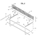
- the handling and supporting structure for cutting machines of the present invention is basically made up by a plurality of approached comb-like elements 12, supporting laminations 14 for said elements 12, and means 16, 18, having by way of example the form of circular section bars, which connect respectively elements 12 and laminations 14.
- Each of said comb-like element 12, preferably obtained from stainless steel is made up by a plurality of identical and aligned needles 20, which develop upwards starting from a longitudinally extended strip 12' forming the base of said element 12 for a height comprised, by way of example, between 20 and 40 mm.
- the comb-like element 12 is defined by a portion 12" which develops orthogonally from base 12' up to the level of needles 20; the height of base 12' and the width of portion 12" are substantially equivalent, and comprised, by way of example between 8 and 15 mm.
- the comb-like element is obtained from a metal strip having a thickness comprised between 0.5 and 1.2 mm.
- the individual needles 20, as shown in Figure 3 and more in detail in Figures 3a and 3b, have a specific configuration, with a side tapering that becomes more marked in correspondence of the upper end forming the point; in particular, said needles 20 reach their maximum width near the point of connection with base 12" of the comb-like element from which they develop, and reduce progressively in width as they approach the upper end; the latter, indicated by 22 in Figure 3a, defines a further more marked tapering, which form a substantially pointed portion whose opposite oblique sides 24, 26 end with horizontal surface 28 having a markedly limited extension, comprised, by way of example, between 0.2 and 0.4 mm, parallel to base 12".
- needles 20 progressively increase in width, forming a cone-shaped portion 30, schematised in detail in Figure 3b. Therefore, needles 20 are alternating with empty sectors, indicated by 32, having a form complementary to the form of said needles; said sectors define, in correspondence of the cone-shaped portion 30 of needles 20, a progressive reduction in width, forming in this way a funnel-shaped profile opening 34.
- the lower end of each of said openings 34 whose width is comprised, by way of example, between 0.1 and 0.5 mm, extends in a portion 36 having, by way of example, a circular development and preferably a diameter equal to or smaller than 2 mm.
- the circular portions 36 are aligned with one another along the upper front of base 12" of the comb-like element 12, and alternate with the cone-shaped portions 30 formed at the lower end of needles 20.
- each head 12" of said comb-like element 12 has a configuration like that of the individual needles 20, defining a marked tapering 38, stressed in particular in Figure 4a, that terminates in a horizontal surface 40 having a width preferably comprised between 0.1 and 0.3 mm.
- each of the comb-like element 12 has a through-hole 42 suitable to house, as will be explained with more details later on, bar 16, which is the connection and stabilisation means for said elements.
- the upper edge of laminations 14 has advantageously an indentation formed by pointed ends 48, having preferably a regular triangular shape, represented in detail in Figure 5a, alternating with slits 50 orthogonally oriented relatively to the lower edge 14' of said laminations; said slits develop from a line corresponding to the base of said pointed ends, extending in lamination 14 for a limited length, comprised, by way of example, between 3 and 6 mm.
- the width of slits 50 is substantially equal to the corresponding height of cavities 44, as measured on the part at the back of their stress raising mouth 44', and to the thickness of the comb-like elements 12.
- Each of the opposite heads 52 of lamination 14 has, on the upper end part indicated by 54 and shown in detail in Figure 5a, a rounded off profile which is connected to a rectilinear portion 56 of a limited extent, parallel to the lower edge 14' of said lamination; from the end part of said rectilinear portion 56, heads 52 develop angularly downwards to connect with one of slits 50.
- laminates 14 couples of superposed through-holes 58, suitable to house bars 18 that connect said laminations with one another, keeping them in a vertical position with the upper indented edge facing upwards.
- Bars 18 and the aforesaid further bars 16, which connects the comb-like elements with one another are preferably obtained from stainless steel and have a diameter complementary to the diameter of holes 58, 42 wherein they are pressure-inserted.
- Figure 2 shows that the assembly of the various pallet-forming components, i.e. the comb-like elements 12, laminations 14 and bars 16, 18 is obtained in a very simple, quick and precise way
- Laminations 14 are vertically oriented, with the upper indented edge facing upwards and are united with one another by bars 18 inserted in holes 58; the many comb-like elements 12 are orthogonally placed relatively to said laminations, with needles 20 oriented upwards and base 12' inserted in slits 50 formed between the pointed ends 48 of said laminations.
- the high pressure liquid coming out of the nozzle incises and goes through the leather, realising the half-finished product with the desired profile; the water jet that meets the points of needles 20 tapered at the upper end 38 does not reverberate but flows downwards along the sides, also tapered, of said needles and is conveyed, through the funnel profile opening 34, into the underlying circular portions 36 from which it flows into the collection basin.
- the narrowing defined by the funnel-openings 34 prevents water from going again upwards in a significant amount.
- the same jet-breaking and anti-reverberation effect is obtained in correspondence of the pointed ends 48 of laminations 14.
- the handling and supporting structure or pallet of the present invention allows to perform the water jet cutting without damaging the leather and does not require the use of an absorbing layer, which would need a frequent replacement, to be placed under said leather.
- the comb-like elements may be oriented to one another in the horizontal and/or vertical or oblique direction, be more or less spaced relatively to one another, and have different sizes and configurations of the needles and the cavities for coupling the supporting lamination, with respect to what has been described and illustrated by way of example; correspondingly said cavities may be more or less spaced relatively to one another, while the indentation formed along the upper edge of the laminations may have a different profile.
- the pallet of the present invention may be replaced by modules made up by a reduced number of comb-like elements, coupleable through any means with one another and/or the supporting laminations.
- the pallet may be utilised also on laser-cutting machines, with comb-like elements and needles possibly from other materials and in the presence of a cutting performed with abrasive-containing water.
Landscapes
- Engineering & Computer Science (AREA)
- Mechanical Engineering (AREA)
- Life Sciences & Earth Sciences (AREA)
- Forests & Forestry (AREA)
- Physics & Mathematics (AREA)
- Optics & Photonics (AREA)
- Plasma & Fusion (AREA)
- Perforating, Stamping-Out Or Severing By Means Other Than Cutting (AREA)
- Organic Low-Molecular-Weight Compounds And Preparation Thereof (AREA)
- Accessories And Tools For Shearing Machines (AREA)
- Feeding Of Workpieces (AREA)
- Harvester Elements (AREA)
Claims (12)
- Structure de support et de manipulation (10) pour des machines de coupe, adaptée en particulier à être appliquée à des machines qui effectuent des opérations de coupe par jet d'eau sur des cuirs, des peaux et des matières synthétiques, comprenant une pluralité d'éléments en forme de peignes (12), obtenus à partir d'une plaque d'épaisseur réduite ; lesdits éléments comportant des côtés qui diminuent de largeur depuis la portion près de la base (12') d'où ils se développent verticalement jusqu'au sommet, caractérisée en ce que ces éléments sont parallèles les uns aux autres et/ou orientés différemment, et formés par des aiguilles rapprochées et alignées (20).
- Structure selon la revendication 1, comprenant un châssis de support pour lesdits éléments en forme de peignes (12) constitué par deux lamelles stratifiées, ou davantage (14), de n'importe quelle forme et dimension, agencées verticalement et transversalement par rapport auxdits éléments (12).
- Structure selon les revendications 1 et 2, dans laquelle les éléments en forme de peignes (12) sont obtenus à partir d'acier inoxydable et les aiguilles (20) formées sur les éléments se développent vers le haut sur une hauteur comprise, à titre d'exemple, entre 20 et 40 mm, la partie (22) correspondant à l'extrémité supérieure desdites aiguilles ayant tendance à être pointue, étant donné qu'elle définit des côtés obliques opposés (24), (26), qui se relient à une surface horizontale (28), parallèle à la base (12'), ayant une extension comprise entre 0,2 et 0,4 mm.
- Structure selon les revendications précédentes, dans laquelle ladite base (12') des éléments (12) est formée par une bande s'étendant longitudinalement ayant une hauteur comprise entre 20 et 40 mm, qui, en correspondance des têtes opposées, s'étend orthogonalement vers le haut (12") jusqu'au niveau des aiguilles (20), avec une conicité (38) à l'extrémité supérieure.
- Structure selon les revendications précédentes, dans laquelle les aiguilles (20) présentent, près du point de connexion avec la base (12') de chacun des éléments (12), une augmentation progressive de largeur, formant une partie en forme de cône (30), alternée avec des secteurs vides (32) d'une forme profilée d'entonnoir complémentaire qui, dans la partie d'extrémité inférieure, définit une ouverture ayant une petite largeur communiquant avec une partie sous-jacente (36) ayant une largeur beaucoup plus grande.
- Structure selon les revendications précédentes, dans laquelle lesdites parties (36) ont un développement circulaire d'un diamètre inférieur ou égal à 2 mm, et sont alignées le long de la face avant supérieure de la base (12') des éléments en forme de peignes (12).
- Structure selon l'une ou plusieurs des revendications précédentes, dans laquelle chacun des éléments en forme de peignes (12) est doté d'un ou de plusieurs trous traversants (42) obtenus le long de la base (12') et/ou en correspondance de l'extension verticale de celle-ci, qui définit des têtes (12"), des tiges de métal (16) d'une section et d'un matériau quelconques pour la connexion desdits éléments (12) étant placées dans lesdits trous.
- Structure selon l'une ou plusieurs des revendications précédentes, dans laquelle, le long de la face avant inférieure des éléments en forme de peignes (12) sont formées deux cavités, ou plus, espacées (44) avec une embouchure d'augmentation de contrainte (44'), ayant une largeur correspondant sensiblement à l'épaisseur des lamelles stratifiées (14), lesdites cavités se développant dans la base (12') sur une longueur d'au moins un tiers de la hauteur totale de ladite base, parallèlement aux têtes (12").
- Structure selon l'une ou plusieurs des revendications précédentes, dans laquelle lesdites lamelles stratifiées (14) sont obtenues à partir d'acier inoxydable ayant une épaisseur équivalant à celle des éléments en forme de peignes (12), ont une configuration sensiblement rectangulaire, une hauteur comprise entre 50 et 100 mm, et le bord supérieur doté d'une denture formée par des extrémités pointues (48), alternant avec des fentes (50) orientées orthogonalement par rapport au bord inférieur (14') desdites lamelles stratifiées, la largeur desdites fentes (50) équivalant sensiblement à l'épaisseur des éléments en forme de peignes (12).
- Structure selon l'une ou plusieurs des revendications précédentes, dans laquelle lesdites fentes (50) se développent dans les lamelles stratifiées (14) depuis une ligne correspondant à la base des extrémités pointues (48) sur une longueur comprise entre 3 et 6 mm.
- Structure selon l'une ou plusieurs des revendications précédentes, dans laquelle des têtes (52) des lamelles stratifiées (14) présentent, dans la partie d'extrémité supérieure (54), un profil arrondi qui se relie à une partie rectiligne (58) d'une extension limitée, et définissent ensuite un profil avec un développement orienté angulairement vers le bas, se reliant avec l'une des fentes (50).
- Structure selon l'une ou plusieurs des revendications précédentes, dans laquelle lesdites lamelles stratifiées (14) sont dotées d'un ou de plusieurs trous traversants (58) pou autant de tiges (18) d'une section et d'un matériau quelconques qui relient lesdites lamelles stratifiées.
Applications Claiming Priority (2)
| Application Number | Priority Date | Filing Date | Title |
|---|---|---|---|
| IT96MI002206A IT1286033B1 (it) | 1996-10-24 | 1996-10-24 | Struttura di movimentazione e supporto per macchine di taglio |
| ITMI962206 | 1996-10-24 |
Publications (2)
| Publication Number | Publication Date |
|---|---|
| EP0838314A1 EP0838314A1 (fr) | 1998-04-29 |
| EP0838314B1 true EP0838314B1 (fr) | 2002-09-18 |
Family
ID=11375085
Family Applications (1)
| Application Number | Title | Priority Date | Filing Date |
|---|---|---|---|
| EP97118042A Expired - Lifetime EP0838314B1 (fr) | 1996-10-24 | 1997-10-17 | Dispositif de manipulation et support pour machines de coupe |
Country Status (6)
| Country | Link |
|---|---|
| US (1) | US6095025A (fr) |
| EP (1) | EP0838314B1 (fr) |
| AT (1) | ATE224267T1 (fr) |
| BR (1) | BR9705320A (fr) |
| DE (1) | DE69715549D1 (fr) |
| IT (1) | IT1286033B1 (fr) |
Cited By (2)
| Publication number | Priority date | Publication date | Assignee | Title |
|---|---|---|---|---|
| EP3738734A1 (fr) * | 2019-05-13 | 2020-11-18 | Open Mind Ventures, S.L.U. | Brosse en soie |
| WO2024261630A1 (fr) * | 2023-06-19 | 2024-12-26 | Tillie Tools Bv | Tapis de sciage de carreaux |
Families Citing this family (23)
| Publication number | Priority date | Publication date | Assignee | Title |
|---|---|---|---|---|
| EP1208935A1 (fr) * | 2000-11-21 | 2002-05-29 | MEIKO Maschinenbau GmbH & Co. | Support pour une tôle |
| RU2180375C1 (ru) * | 2001-02-27 | 2002-03-10 | Орловский государственный технический университет | Установка для раскроя текстильных материалов сверхзвуковой струей жидкости |
| RU2180374C1 (ru) * | 2001-02-27 | 2002-03-10 | Орловский государственный технический университет | Установка для раскроя текстильных материалов сверхзвуковой струей жидкости |
| US6634928B2 (en) | 2001-11-09 | 2003-10-21 | International Business Machines Corporation | Fluid jet cutting method and apparatus |
| US6770845B1 (en) * | 2003-01-29 | 2004-08-03 | Franz Noest | Supporting structure for sheet material |
| DE102004029359B4 (de) * | 2004-06-17 | 2006-08-03 | Siemens Ag | Vorrichtung zum Lagern eines Gegenstandes |
| EP2029312B1 (fr) * | 2006-05-24 | 2013-01-23 | TRUMPF Werkzeugmaschinen GmbH + Co. KG | Installation d'usinage avec un porte-pièce pour recevoir une pièce à usiner notamment ous forme d'empilements, avec des élements de support pouvant être montés sur des élements d'appui |
| US7792602B2 (en) * | 2006-08-22 | 2010-09-07 | Precision Automation, Inc. | Material processing system and a material processing method including a saw station and an interface with touch screen |
| US7946906B2 (en) | 2007-06-04 | 2011-05-24 | Black & Decker Inc. | Tile saw with laser guide |
| US7810482B2 (en) * | 2007-06-04 | 2010-10-12 | Black & Decker Inc. | Tile cutting machine |
| JP5448784B2 (ja) * | 2009-12-18 | 2014-03-19 | 三菱重工業株式会社 | ショットピーニング装置 |
| MY155758A (en) * | 2010-01-06 | 2015-11-30 | Shinetsu Chemical Co | Rare earth magnet holding jig and cutting machine |
| MY157471A (en) * | 2010-01-06 | 2016-06-15 | Shinetsu Chemical Co | Rare earth magnet holding jig, cutting machine and cutting method |
| US11045969B2 (en) * | 2011-07-28 | 2021-06-29 | Flow International Corporation | Catcher tank assembly of waterjet cutting system |
| CN103930239B (zh) | 2011-09-02 | 2018-06-22 | 艾根系统有限公司 | 切割台 |
| US9266199B2 (en) * | 2013-01-08 | 2016-02-23 | Fedtech, Inc. | Copper-tipped slats for laser cutting |
| CN103273203B (zh) * | 2013-06-13 | 2015-03-11 | 沈阳飞机工业(集团)有限公司 | 一种零件支撑装置 |
| US9902019B2 (en) * | 2013-09-11 | 2018-02-27 | Hoosier Laser, Inc. | Minimal contact modular laser cutting table system |
| CN105415427A (zh) * | 2015-12-15 | 2016-03-23 | 镇江市世龙食品机械有限公司 | 一种海带切丝机上的钢梳 |
| JP6953346B2 (ja) * | 2018-03-29 | 2021-10-27 | メタウォーター株式会社 | シート状軟質材の切断装置 |
| US11607891B2 (en) | 2019-09-27 | 2023-03-21 | Hill-Rom Services, Inc. | Method of roll-to-roll digital printing, cutting, and punching of medical device surfaces |
| FR3108547B1 (fr) * | 2020-03-27 | 2022-04-01 | Lectra | Elément modulaire de support de coupe à aspiration d’une machine de coupe automatique de matériaux en feuilles |
| EP3964463A1 (fr) * | 2020-09-07 | 2022-03-09 | Bobst Mex Sa | Dispositif de support pour le stockage ou le transport de feuilles individuelles ou de piles d'un matériau d'emballage et ensemble de bandes transporteuses |
Family Cites Families (28)
| Publication number | Priority date | Publication date | Assignee | Title |
|---|---|---|---|---|
| US245149A (en) * | 1881-08-02 | fowler | ||
| US245150A (en) * | 1881-08-02 | Assigknoe to | ||
| US289594A (en) * | 1883-12-04 | Machine for cutting furs | ||
| US1965780A (en) * | 1933-05-01 | 1934-07-10 | Oluf E Odland | Box-making frame |
| US2258898A (en) * | 1941-05-24 | 1941-10-14 | Frederick A Lang | Rolled material cutting table |
| US3340341A (en) * | 1963-07-01 | 1967-09-05 | Dow Chemical Co | Method of preparing grids |
| US4137804A (en) * | 1974-07-12 | 1979-02-06 | Gerber Garment Technology, Inc. | Fluid cutting jet receiver |
| US4205835A (en) * | 1977-05-13 | 1980-06-03 | Gerber Garment Technology, Inc. | Bristle bed for vacuum table |
| US4112797A (en) * | 1977-10-07 | 1978-09-12 | Gerber Garment Technology, Inc. | Fluid jet cutting apparatus |
| US4312254A (en) * | 1977-10-07 | 1982-01-26 | Gerber Garment Technology, Inc. | Fluid jet apparatus for cutting sheet material |
| US4685363A (en) * | 1985-05-22 | 1987-08-11 | Gerber Scientific, Inc. | Apparatus and method for supporting and working on sheet material |
| GB2175237B (en) * | 1985-05-22 | 1988-07-27 | Gerber Scient Inc | Apparatus and method for supporting and working on sheet material |
| JPS6352790A (ja) * | 1986-08-21 | 1988-03-05 | Mitsubishi Electric Corp | レ−ザ加工装置 |
| SU1504016A1 (ru) * | 1987-05-05 | 1989-08-30 | Предприятие П/Я А-1944 | Стол устройства дл резки листового материала струей воды |
| SU1604549A1 (ru) * | 1989-01-26 | 1990-11-07 | Предприятие П/Я Р-6115 | Устройство дл базировани деталей при обработке сквозных отверстий |
| DE3932850A1 (de) * | 1989-03-30 | 1991-03-07 | Duerkopp System Technik Gmbh | Arbeitstisch mit einer metallischen schneidgutunterlage fuer eine automatische schneidanlage |
| SU1669651A1 (ru) * | 1989-08-18 | 1991-08-15 | Научно-производственное объединение "Аметист" | Рабочий стол устройства дл резки струей воды |
| FR2651712A1 (fr) * | 1989-09-12 | 1991-03-15 | Isin | Table-support pour machine de decoupe par jet d'eau. |
| US5049723A (en) * | 1990-03-20 | 1991-09-17 | Cincinnati Incorporated | System for detecting penetration of a blank |
| JP2547681B2 (ja) * | 1991-09-06 | 1996-10-23 | 株式会社島精機製作所 | 自動裁断機における裁断支持面用ブラシ取付構造 |
| US5207140A (en) * | 1991-09-10 | 1993-05-04 | Gerber Garment Technol | Cloth cutter bed made from elongate support members |
| US5241733A (en) * | 1991-09-10 | 1993-09-07 | Geber Garment Technology, Inc. | Method of making a cloth cutter bristle bed from elongate support members |
| US5487930A (en) * | 1991-10-03 | 1996-01-30 | Tolo, Inc. | Three structure structural element with interlocking ribbing |
| JPH06683A (ja) * | 1992-06-23 | 1994-01-11 | Amada Co Ltd | 熱切断加工機用加工テーブルの製作方法及び熱切断加工機用加工テーブル |
| NL9201402A (nl) * | 1992-08-04 | 1994-03-01 | Meyn Maschf | Transportband. |
| JP2674444B2 (ja) * | 1992-11-12 | 1997-11-12 | 日本鋼管株式会社 | レーザー切断機用定盤 |
| JPH0852575A (ja) * | 1994-08-12 | 1996-02-27 | Komatsu Ltd | 熱切断加工機のワーク搬送装置 |
| IT1279409B1 (it) * | 1995-11-13 | 1997-12-10 | Fk Systema S R L | Blocco modulare per la formazione di piani aspiranti in macchine per il taglio di tessuti con una lama libera a movimento alternativo |
-
1996
- 1996-10-24 IT IT96MI002206A patent/IT1286033B1/it active IP Right Grant
-
1997
- 1997-10-17 AT AT97118042T patent/ATE224267T1/de not_active IP Right Cessation
- 1997-10-17 EP EP97118042A patent/EP0838314B1/fr not_active Expired - Lifetime
- 1997-10-17 DE DE69715549T patent/DE69715549D1/de not_active Expired - Lifetime
- 1997-10-20 US US08/954,707 patent/US6095025A/en not_active Expired - Fee Related
- 1997-10-23 BR BR9705320A patent/BR9705320A/pt not_active IP Right Cessation
Cited By (2)
| Publication number | Priority date | Publication date | Assignee | Title |
|---|---|---|---|---|
| EP3738734A1 (fr) * | 2019-05-13 | 2020-11-18 | Open Mind Ventures, S.L.U. | Brosse en soie |
| WO2024261630A1 (fr) * | 2023-06-19 | 2024-12-26 | Tillie Tools Bv | Tapis de sciage de carreaux |
Also Published As
| Publication number | Publication date |
|---|---|
| US6095025A (en) | 2000-08-01 |
| IT1286033B1 (it) | 1998-07-07 |
| ATE224267T1 (de) | 2002-10-15 |
| ITMI962206A1 (it) | 1998-04-24 |
| BR9705320A (pt) | 1999-03-23 |
| DE69715549D1 (de) | 2002-10-24 |
| EP0838314A1 (fr) | 1998-04-29 |
Similar Documents
| Publication | Publication Date | Title |
|---|---|---|
| EP0838314B1 (fr) | Dispositif de manipulation et support pour machines de coupe | |
| FI63534C (fi) | Hushaollsanordning foer att skaera potatis groensaker frukt eler dylikt i skivor eller liknande | |
| KR101954302B1 (ko) | 테이블용 팔레트를 구비하는 레이저 절단기 | |
| US20040007114A1 (en) | Steel rule die with removable cutting units | |
| JP6411303B2 (ja) | スライサー | |
| DE2356116A1 (de) | Transportvorrichtung zum abfuehren von gegenstaenden aus einer stanzpresse | |
| EP1356896A2 (fr) | Tampon d'aspiration | |
| DE3601671C2 (de) | Vorrichtung und Verfahren zum Sieben oder Klassieren von Haufwerk | |
| DE102013104045B3 (de) | Vorrichtung zur Präsentation von Waren | |
| US3972262A (en) | Printed circuit board support | |
| EP0958067A1 (fr) | Crible dote d'elements a toile de criblage allonges se chevauchant | |
| DE202011050864U1 (de) | Luftklinge | |
| DE102013012098B4 (de) | Vorrichtung zum Ausstanzen von Teigstücken | |
| KR20130040113A (ko) | 근채류 절단장치 | |
| EP0229868A1 (fr) | Dispositif pour la production de fromage | |
| CN216911257U (zh) | 清洗装置 | |
| DE602005022799D1 (de) | Vorrichtung zur Entfernung von Abfall von Rollen aus bahnartigem Material | |
| KR102318608B1 (ko) | 건멸치 내장 제거장치 | |
| US3095916A (en) | Grid for disintegrating fibrous materials | |
| DE202013006520U1 (de) | Vorrichtung zum Ausstanzen von Teigstücken | |
| RU48248U1 (ru) | Устройство для формирования отверстий | |
| EP1790464A3 (fr) | Presse pour le revêtement sur plusieurs cotés d'éléments avec un matériau en feuille, en particulier pour le revêtement des composants en bois de meubles, portes ou fenêtres avec une feuille en matériau synthétique | |
| DE102010003089A1 (de) | Kühlbehälteranordnung | |
| DE693758C (de) | Auflageplatte fuer das Schneidgut bei Aufschnittschneidemaschinen | |
| DE1759535U (de) | Einrichtung zum schneiden von kartoffeln in scheiben- oder plaettchenform. |
Legal Events
| Date | Code | Title | Description |
|---|---|---|---|
| PUAI | Public reference made under article 153(3) epc to a published international application that has entered the european phase |
Free format text: ORIGINAL CODE: 0009012 |
|
| AK | Designated contracting states |
Kind code of ref document: A1 Designated state(s): AT BE CH DE DK ES FI FR GB GR IE LI LU MC NL PT SE |
|
| AX | Request for extension of the european patent |
Free format text: AL;LT;LV;RO;SI |
|
| 17P | Request for examination filed |
Effective date: 19980921 |
|
| AKX | Designation fees paid |
Free format text: AT BE CH DE DK ES FI FR GB GR IE LI LU MC NL PT SE |
|
| RBV | Designated contracting states (corrected) |
Designated state(s): AT BE CH DE DK ES FI FR GB GR IE LI LU MC NL PT SE |
|
| GRAG | Despatch of communication of intention to grant |
Free format text: ORIGINAL CODE: EPIDOS AGRA |
|
| 17Q | First examination report despatched |
Effective date: 20011217 |
|
| GRAG | Despatch of communication of intention to grant |
Free format text: ORIGINAL CODE: EPIDOS AGRA |
|
| GRAG | Despatch of communication of intention to grant |
Free format text: ORIGINAL CODE: EPIDOS AGRA |
|
| GRAH | Despatch of communication of intention to grant a patent |
Free format text: ORIGINAL CODE: EPIDOS IGRA |
|
| GRAH | Despatch of communication of intention to grant a patent |
Free format text: ORIGINAL CODE: EPIDOS IGRA |
|
| GRAA | (expected) grant |
Free format text: ORIGINAL CODE: 0009210 |
|
| AK | Designated contracting states |
Kind code of ref document: B1 Designated state(s): AT BE CH DE DK ES FI FR GB GR IE LI LU MC NL PT SE |
|
| PG25 | Lapsed in a contracting state [announced via postgrant information from national office to epo] |
Ref country code: NL Free format text: LAPSE BECAUSE OF FAILURE TO SUBMIT A TRANSLATION OF THE DESCRIPTION OR TO PAY THE FEE WITHIN THE PRESCRIBED TIME-LIMIT Effective date: 20020918 Ref country code: LI Free format text: LAPSE BECAUSE OF FAILURE TO SUBMIT A TRANSLATION OF THE DESCRIPTION OR TO PAY THE FEE WITHIN THE PRESCRIBED TIME-LIMIT Effective date: 20020918 Ref country code: GR Free format text: LAPSE BECAUSE OF FAILURE TO SUBMIT A TRANSLATION OF THE DESCRIPTION OR TO PAY THE FEE WITHIN THE PRESCRIBED TIME-LIMIT Effective date: 20020918 Ref country code: FR Free format text: LAPSE BECAUSE OF FAILURE TO SUBMIT A TRANSLATION OF THE DESCRIPTION OR TO PAY THE FEE WITHIN THE PRESCRIBED TIME-LIMIT Effective date: 20020918 Ref country code: FI Free format text: LAPSE BECAUSE OF FAILURE TO SUBMIT A TRANSLATION OF THE DESCRIPTION OR TO PAY THE FEE WITHIN THE PRESCRIBED TIME-LIMIT Effective date: 20020918 Ref country code: CH Free format text: LAPSE BECAUSE OF FAILURE TO SUBMIT A TRANSLATION OF THE DESCRIPTION OR TO PAY THE FEE WITHIN THE PRESCRIBED TIME-LIMIT Effective date: 20020918 Ref country code: BE Free format text: LAPSE BECAUSE OF FAILURE TO SUBMIT A TRANSLATION OF THE DESCRIPTION OR TO PAY THE FEE WITHIN THE PRESCRIBED TIME-LIMIT Effective date: 20020918 Ref country code: AT Free format text: LAPSE BECAUSE OF FAILURE TO SUBMIT A TRANSLATION OF THE DESCRIPTION OR TO PAY THE FEE WITHIN THE PRESCRIBED TIME-LIMIT Effective date: 20020918 |
|
| REF | Corresponds to: |
Ref document number: 224267 Country of ref document: AT Date of ref document: 20021015 Kind code of ref document: T |
|
| REG | Reference to a national code |
Ref country code: GB Ref legal event code: FG4D |
|
| REG | Reference to a national code |
Ref country code: CH Ref legal event code: EP |
|
| REG | Reference to a national code |
Ref country code: IE Ref legal event code: FG4D |
|
| PG25 | Lapsed in a contracting state [announced via postgrant information from national office to epo] |
Ref country code: LU Free format text: LAPSE BECAUSE OF NON-PAYMENT OF DUE FEES Effective date: 20021017 Ref country code: IE Free format text: LAPSE BECAUSE OF NON-PAYMENT OF DUE FEES Effective date: 20021017 |
|
| REF | Corresponds to: |
Ref document number: 69715549 Country of ref document: DE Date of ref document: 20021024 |
|
| PG25 | Lapsed in a contracting state [announced via postgrant information from national office to epo] |
Ref country code: SE Free format text: LAPSE BECAUSE OF FAILURE TO SUBMIT A TRANSLATION OF THE DESCRIPTION OR TO PAY THE FEE WITHIN THE PRESCRIBED TIME-LIMIT Effective date: 20021218 Ref country code: GB Free format text: LAPSE BECAUSE OF NON-PAYMENT OF DUE FEES Effective date: 20021218 Ref country code: DK Free format text: LAPSE BECAUSE OF FAILURE TO SUBMIT A TRANSLATION OF THE DESCRIPTION OR TO PAY THE FEE WITHIN THE PRESCRIBED TIME-LIMIT Effective date: 20021218 |
|
| PG25 | Lapsed in a contracting state [announced via postgrant information from national office to epo] |
Ref country code: PT Free format text: LAPSE BECAUSE OF FAILURE TO SUBMIT A TRANSLATION OF THE DESCRIPTION OR TO PAY THE FEE WITHIN THE PRESCRIBED TIME-LIMIT Effective date: 20021219 Ref country code: DE Free format text: LAPSE BECAUSE OF FAILURE TO SUBMIT A TRANSLATION OF THE DESCRIPTION OR TO PAY THE FEE WITHIN THE PRESCRIBED TIME-LIMIT Effective date: 20021219 |
|
| NLV1 | Nl: lapsed or annulled due to failure to fulfill the requirements of art. 29p and 29m of the patents act | ||
| PG25 | Lapsed in a contracting state [announced via postgrant information from national office to epo] |
Ref country code: ES Free format text: LAPSE BECAUSE OF FAILURE TO SUBMIT A TRANSLATION OF THE DESCRIPTION OR TO PAY THE FEE WITHIN THE PRESCRIBED TIME-LIMIT Effective date: 20030328 |
|
| REG | Reference to a national code |
Ref country code: CH Ref legal event code: PL |
|
| PG25 | Lapsed in a contracting state [announced via postgrant information from national office to epo] |
Ref country code: MC Free format text: LAPSE BECAUSE OF NON-PAYMENT OF DUE FEES Effective date: 20030501 |
|
| EN | Fr: translation not filed | ||
| PLBE | No opposition filed within time limit |
Free format text: ORIGINAL CODE: 0009261 |
|
| STAA | Information on the status of an ep patent application or granted ep patent |
Free format text: STATUS: NO OPPOSITION FILED WITHIN TIME LIMIT |
|
| GBPC | Gb: european patent ceased through non-payment of renewal fee |
Effective date: 20021218 |
|
| REG | Reference to a national code |
Ref country code: IE Ref legal event code: MM4A |
|
| 26N | No opposition filed |
Effective date: 20030619 |