EP0838324A2 - Procédé et appareil pour le soudage de profilés, coupés en onglet et comportant des joints d'étanchéité incorporés, pour la fabrication de cadres en matières plastique - Google Patents
Procédé et appareil pour le soudage de profilés, coupés en onglet et comportant des joints d'étanchéité incorporés, pour la fabrication de cadres en matières plastique Download PDFInfo
- Publication number
- EP0838324A2 EP0838324A2 EP97117744A EP97117744A EP0838324A2 EP 0838324 A2 EP0838324 A2 EP 0838324A2 EP 97117744 A EP97117744 A EP 97117744A EP 97117744 A EP97117744 A EP 97117744A EP 0838324 A2 EP0838324 A2 EP 0838324A2
- Authority
- EP
- European Patent Office
- Prior art keywords
- welding
- miter
- seal
- stamp
- frame profiles
- Prior art date
- Legal status (The legal status is an assumption and is not a legal conclusion. Google has not performed a legal analysis and makes no representation as to the accuracy of the status listed.)
- Granted
Links
Images





Classifications
-
- B—PERFORMING OPERATIONS; TRANSPORTING
- B29—WORKING OF PLASTICS; WORKING OF SUBSTANCES IN A PLASTIC STATE IN GENERAL
- B29C—SHAPING OR JOINING OF PLASTICS; SHAPING OF MATERIAL IN A PLASTIC STATE, NOT OTHERWISE PROVIDED FOR; AFTER-TREATMENT OF THE SHAPED PRODUCTS, e.g. REPAIRING
- B29C65/00—Joining or sealing of preformed parts, e.g. welding of plastics materials; Apparatus therefor
- B29C65/02—Joining or sealing of preformed parts, e.g. welding of plastics materials; Apparatus therefor by heating, with or without pressure
- B29C65/18—Joining or sealing of preformed parts, e.g. welding of plastics materials; Apparatus therefor by heating, with or without pressure using heated tools
- B29C65/20—Joining or sealing of preformed parts, e.g. welding of plastics materials; Apparatus therefor by heating, with or without pressure using heated tools with direct contact, e.g. using "mirror"
-
- B—PERFORMING OPERATIONS; TRANSPORTING
- B29—WORKING OF PLASTICS; WORKING OF SUBSTANCES IN A PLASTIC STATE IN GENERAL
- B29C—SHAPING OR JOINING OF PLASTICS; SHAPING OF MATERIAL IN A PLASTIC STATE, NOT OTHERWISE PROVIDED FOR; AFTER-TREATMENT OF THE SHAPED PRODUCTS, e.g. REPAIRING
- B29C66/00—General aspects of processes or apparatus for joining preformed parts
- B29C66/01—General aspects dealing with the joint area or with the area to be joined
- B29C66/05—Particular design of joint configurations
- B29C66/10—Particular design of joint configurations particular design of the joint cross-sections
- B29C66/11—Joint cross-sections comprising a single joint-segment, i.e. one of the parts to be joined comprising a single joint-segment in the joint cross-section
- B29C66/116—Single bevelled joints, i.e. one of the parts to be joined being bevelled in the joint area
- B29C66/1162—Single bevel to bevel joints, e.g. mitre joints
-
- B—PERFORMING OPERATIONS; TRANSPORTING
- B29—WORKING OF PLASTICS; WORKING OF SUBSTANCES IN A PLASTIC STATE IN GENERAL
- B29C—SHAPING OR JOINING OF PLASTICS; SHAPING OF MATERIAL IN A PLASTIC STATE, NOT OTHERWISE PROVIDED FOR; AFTER-TREATMENT OF THE SHAPED PRODUCTS, e.g. REPAIRING
- B29C66/00—General aspects of processes or apparatus for joining preformed parts
- B29C66/01—General aspects dealing with the joint area or with the area to be joined
- B29C66/32—Measures for keeping the burr form under control; Avoiding burr formation; Shaping the burr
- B29C66/326—Shaping the burr, e.g. by the joining tool
-
- B—PERFORMING OPERATIONS; TRANSPORTING
- B29—WORKING OF PLASTICS; WORKING OF SUBSTANCES IN A PLASTIC STATE IN GENERAL
- B29C—SHAPING OR JOINING OF PLASTICS; SHAPING OF MATERIAL IN A PLASTIC STATE, NOT OTHERWISE PROVIDED FOR; AFTER-TREATMENT OF THE SHAPED PRODUCTS, e.g. REPAIRING
- B29C66/00—General aspects of processes or apparatus for joining preformed parts
- B29C66/50—General aspects of joining tubular articles; General aspects of joining long products, i.e. bars or profiled elements; General aspects of joining single elements to tubular articles, hollow articles or bars; General aspects of joining several hollow-preforms to form hollow or tubular articles
- B29C66/51—Joining tubular articles, profiled elements or bars; Joining single elements to tubular articles, hollow articles or bars; Joining several hollow-preforms to form hollow or tubular articles
- B29C66/52—Joining tubular articles, bars or profiled elements
- B29C66/524—Joining profiled elements
- B29C66/5243—Joining profiled elements for forming corner connections, e.g. for making window frames or V-shaped pieces
- B29C66/52431—Joining profiled elements for forming corner connections, e.g. for making window frames or V-shaped pieces with a right angle, e.g. for making L-shaped pieces
-
- B—PERFORMING OPERATIONS; TRANSPORTING
- B29—WORKING OF PLASTICS; WORKING OF SUBSTANCES IN A PLASTIC STATE IN GENERAL
- B29C—SHAPING OR JOINING OF PLASTICS; SHAPING OF MATERIAL IN A PLASTIC STATE, NOT OTHERWISE PROVIDED FOR; AFTER-TREATMENT OF THE SHAPED PRODUCTS, e.g. REPAIRING
- B29C66/00—General aspects of processes or apparatus for joining preformed parts
- B29C66/70—General aspects of processes or apparatus for joining preformed parts characterised by the composition, physical properties or the structure of the material of the parts to be joined; Joining with non-plastics material
- B29C66/72—General aspects of processes or apparatus for joining preformed parts characterised by the composition, physical properties or the structure of the material of the parts to be joined; Joining with non-plastics material characterised by the structure of the material of the parts to be joined
- B29C66/725—General aspects of processes or apparatus for joining preformed parts characterised by the composition, physical properties or the structure of the material of the parts to be joined; Joining with non-plastics material characterised by the structure of the material of the parts to be joined being hollow-walled or honeycombs
- B29C66/7252—General aspects of processes or apparatus for joining preformed parts characterised by the composition, physical properties or the structure of the material of the parts to be joined; Joining with non-plastics material characterised by the structure of the material of the parts to be joined being hollow-walled or honeycombs hollow-walled
- B29C66/72523—General aspects of processes or apparatus for joining preformed parts characterised by the composition, physical properties or the structure of the material of the parts to be joined; Joining with non-plastics material characterised by the structure of the material of the parts to be joined being hollow-walled or honeycombs hollow-walled multi-channelled or multi-tubular
-
- E—FIXED CONSTRUCTIONS
- E06—DOORS, WINDOWS, SHUTTERS, OR ROLLER BLINDS IN GENERAL; LADDERS
- E06B—FIXED OR MOVABLE CLOSURES FOR OPENINGS IN BUILDINGS, VEHICLES, FENCES OR LIKE ENCLOSURES IN GENERAL, e.g. DOORS, WINDOWS, BLINDS, GATES
- E06B3/00—Window sashes, door leaves, or like elements for closing wall or like openings; Layout of fixed or moving closures, e.g. windows in wall or like openings; Features of rigidly-mounted outer frames relating to the mounting of wing frames
- E06B3/96—Corner joints or edge joints for windows, doors, or the like frames or wings
- E06B3/9604—Welded or soldered joints
- E06B3/9608—Mitre joints
-
- B—PERFORMING OPERATIONS; TRANSPORTING
- B29—WORKING OF PLASTICS; WORKING OF SUBSTANCES IN A PLASTIC STATE IN GENERAL
- B29C—SHAPING OR JOINING OF PLASTICS; SHAPING OF MATERIAL IN A PLASTIC STATE, NOT OTHERWISE PROVIDED FOR; AFTER-TREATMENT OF THE SHAPED PRODUCTS, e.g. REPAIRING
- B29C66/00—General aspects of processes or apparatus for joining preformed parts
- B29C66/50—General aspects of joining tubular articles; General aspects of joining long products, i.e. bars or profiled elements; General aspects of joining single elements to tubular articles, hollow articles or bars; General aspects of joining several hollow-preforms to form hollow or tubular articles
- B29C66/51—Joining tubular articles, profiled elements or bars; Joining single elements to tubular articles, hollow articles or bars; Joining several hollow-preforms to form hollow or tubular articles
- B29C66/55—Joining tubular articles, profiled elements or bars; Joining single elements to tubular articles, hollow articles or bars; Joining several hollow-preforms to form hollow or tubular articles sealing elements being incorporated into the joints, e.g. gaskets
-
- B—PERFORMING OPERATIONS; TRANSPORTING
- B29—WORKING OF PLASTICS; WORKING OF SUBSTANCES IN A PLASTIC STATE IN GENERAL
- B29L—INDEXING SCHEME ASSOCIATED WITH SUBCLASS B29C, RELATING TO PARTICULAR ARTICLES
- B29L2031/00—Other particular articles
- B29L2031/001—Profiled members, e.g. beams, sections
- B29L2031/003—Profiled members, e.g. beams, sections having a profiled transverse cross-section
- B29L2031/005—Profiled members, e.g. beams, sections having a profiled transverse cross-section for making window frames
-
- B—PERFORMING OPERATIONS; TRANSPORTING
- B29—WORKING OF PLASTICS; WORKING OF SUBSTANCES IN A PLASTIC STATE IN GENERAL
- B29L—INDEXING SCHEME ASSOCIATED WITH SUBCLASS B29C, RELATING TO PARTICULAR ARTICLES
- B29L2031/00—Other particular articles
- B29L2031/001—Profiled members, e.g. beams, sections
- B29L2031/003—Profiled members, e.g. beams, sections having a profiled transverse cross-section
- B29L2031/005—Profiled members, e.g. beams, sections having a profiled transverse cross-section for making window frames
- B29L2031/006—Profiled members, e.g. beams, sections having a profiled transverse cross-section for making window frames and provided with a sealing element
Definitions
- the invention relates to a method for welding miter cut plastic frame profiles with retracted, over the entire Profile length extending, from a mounting foot and at least one Sealing lip existing seals made of a weldable material, preferably from a thermoplastic, for windows or doors, in which the miter surfaces and the neighboring frame profile areas by a welding mirror to the welding temperature be heated up, the welding mirror from the area the mitred surfaces are removed and the mitred surfaces of the frame profiles be pressed together.
- the invention also relates to devices for performing the method.
- the invention has for its object a method of the type mentioned and to design an apparatus for performing the method so that the elastic Function of the seal in the corner area is retained.
- this object is characterized by the features of the Part of claim 1 solved.
- the molded part which covers the seal, prevents the frame profiles from being welded together and the seals in this area the formation of a weld bead, so that the elasticity of the seal in the corner area is not negatively affected by the welding. is influenced, especially since the welding bead formed on the outside of the seal can be easily removed.
- the outer contour of the seal adjacent to the Miter level are covered by molded parts, being in the miter level Gap for the exit of the welding bead remains. After welding the Frame profiles and the gaskets become the molded parts and are on the outside the weld bead formed in the seal is removed.
- Fig. 1 are two to be welded, mitred frame profiles 1 shown, which are designed as plastic hollow profiles. In these frame profiles namely in corresponding anchoring grooves seals 2,3 are drawn in extend over the entire length of the profile.
- the frame profiles 1 are placed on a table Welding machine arranged and held in devices which are essentially Grasp the visible and functional surfaces of the frame profiles. These encompassing device parts 4 are referred to as supplements or welding bead limits.
- the miter surfaces of the frame profiles 1 are on a welding mirror 5 through which the miter surfaces and the adjacent areas of the Frame profiles can be heated. The heat transfer takes place through Heat conduction.
- the parts of the device forming the supplements or the weld bead limitations 4 are at a distance S, which is approximately 3 mm, from the profile miter surface to be welded arranged. This distance forms the so-called welding allowance.
- FIG. 3 The next process step is shown in FIG. 3, in which the miter surfaces are pressed against each other. Due to the plastic deformation of the through Heating the plasticized edge material, the frame profiles 2 in this Area brought together so far that the remaining gap a between the device parts 4, which form the supplements or welding bead limits, only is still 0.2 to 0.3 mm.
- Fig. 4 shows two miter-cut frame profiles 1a, on the miter surfaces 1b is the plasticizable welding allowance that will later be displaced S joins as well as the direction of the welding forces F, which displaces the effect plasticized material up to the overlap of lines 1c. That while material of the plasticized welding allowance S partly flows in the hollow chambers of the frame profile 1 and 1a and becomes one approximately the same part is pushed outwards beyond the profile jacket surfaces.
- FIG. 5 shows two frame profiles welded in the miter area with a viewing direction shown along the miter joint.
- the supplements or welding bead limits forming device parts 4 are for weld or miter tapered towards the end and almost end in a point.
- the tips of the weld bead boundaries form forming device parts 4 a distance of 0.2 to 0.3 mm to each other, so that the plasticized material displaced to the outside is almost heart-shaped over the Pointed welding bead boundaries in the thereby formed Exit space.
- Such weld beads also form in the area of the retracted seals 2,3 and mix there with the plasticized and displaced material of Frame profiles.
- the mixing of hard and soft materials leads to a block-like, essentially inelastic area of the interconnected in the corner Seals.
- Fig. 6 shows a frame profile 7, which with a stop seal 8 and with a Glass system seal 9 is equipped.
- Line 10 gives the stop surface of the frame profile with which the frame profile 7 interacts in the overall window while the line 11 indicates the surface of the glass on which the seal 9 is elastic deformed.
- the device parts forming the supplements or welding bead limits are formed in the immediate corner area of the seals so that by means of Stamp 12.13 the seals 8.9 during the welding process to a measure be compressed, which corresponds to the levels of lines 10 and 11. After this Hardening of the welded corner results in a hard, inelastic sealing corner, which is shown in FIGS. 7a and 7b.
- the inelastic The area lies on both sides of the miter plane, which is shown in FIGS. 7a and 7b is shown by the vertical center line.
- the sealing corners are from special meaning.
- the shape of the seal in the miter corner and in front all the necessary elasticity over the entire effective range of the seal is necessary for the perfect tightness of such elements.
- the sash and frame of a window or door are made using fittings connected to each other, e.g. in grooves of the frame profiles but also in particular recesses to be manufactured are arranged in the profiles. This creates Tolerances so that the actual plant level, e.g. the seal 8 around the theoretical contact surface 10 according to FIG. 6 fluctuate in both directions can.
- FIGS. 8 to 17 The object of the invention is shown in FIGS. 8 to 17 and is described below described.
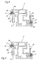
- Fig. 8 shows a frame profile 1 with inserted in anchoring grooves 2a and 3a Seals 2 and 3, where the inner contour of the seal is from the mounting foot 2b or 3b and is determined by the sealing lip 2c and 3c by a as Stamp 14 or 15 formed part is covered.
- the stamps are 14, 15 are angular and have lateral projecting legs 14a and 15a. These legs are adapted to the inner contour of the seal 2 or 3 and are supported during the welding on the mounting foot 2b or 3b from.
- the legs 14a and 15a are not in the embodiment according to FIG. 1 completely adapted to the inner contour of the seal and do not cover it form-fitting completely, so that there is a welding bead with small dimensions can form in the area of the miter corner of the seal. This welding bead with Small dimensions affect the elasticity of the seal in the miter area only insignificant.
- the legs 14 and 15a are the stamp 14 and 15 designed so that they flush the inner contour of the seal 2 or 3 are adjusted.
- the leg 15a has a recess for receiving the sealing lip 3c and for receiving projections of the mounting foot 3b on.
- the stamp 14, 15 can be in the direction of the arrows S1 and S2 in the inner contour of the Seals can be inserted. But there is also the option of using the stamp their legs 14a and 15a in the delimited by the inner contour of the seals Swivel in space.
- Fig. 10 corresponds to Fig. 8, but is the frame profile on the outside or on the visible surface a device part 16, which is a supplement or a Weld bead limitation forms, assigned.
- the legs 14a and 15a of the stamp 14 and 15 only limit the Sealing foot and leave a weld bead with little inside the sealing lip Dimensions too.
- cover parts 17, 18 for the outer contour of the sealing lips 2c and 3c Stamp assigned, with corresponding recesses for the adjacent recording the sealing lips 2c, 3c are equipped.
- the legs 14a and 15a are the inner contour of the seals 2 and 3 closely adapted and also, as shown in Fig. 9, with recesses for receiving equipped with sealing lip parts and protrusions on the mounting foot, so that in the interior of the seals in the miter area a weld bead cannot arise from sealing material.
- the leg of the stamp can be used as an angle piece adapted to the mitred corner be trained.
- Fig. 12 shows a miter corner in the frame profiles 1 after the plasticizing process and the removal of the welding mirror 5 still at a distance from the Width of the welding mirror.
- the stamp 14 is on the Attachment foot 2b placed and moved under the sealing lip 2c and there fixed.
- the angular stamp 14 is supported on surfaces of the insert parts 17 and is thus with his legs through the system on the insert parts in the end position of the welded corner shown in FIG. 13. After welding the angular stamp 14 is shown in dot-dash lines Position moved out of the corner and can then go up from the area of the corner be removed.
- the stamp end 19, on the side projecting leg 14a facing away End extends into a spring chamber 20 of a receiving part 21 and is loaded there with a spring 22.
- the receiving part has an inclined surface 23 equipped, which in the course of the shutdown of the receiving part in the direction of Arrow 24 cooperates with a profile edge 25, so that the receiving part with the Stamp moved away from the frame profile 1 and the leg 14a of the stamp 14 is inserted into the inner contour of the seal 2.
- the end position is in Fig. 15 shown.
- the demolding takes place by a movement of the receiving part 21 in Direction of arrow 26.
- Fig. 16 shows another construction of a stamp to cover the inner contour of the seal 2.
- the stamp is made up of the parts 27 and 28 together, which touch flush in the miter surface.
- the stamps 27 and 28 have a drivable guide piece 29, which in an inclined guideway 30 can perform a stroke h.
- the drive the guide piece 29 can be done pneumatically or hydraulically.
- the drives 27 and 28 can be moved into the respective operative position.
- a spring compensation 31 must only be provided parallel to the frame profiles to the movements during the welding process, namely the processing the welding allowance to compensate.
- the punches 27 and 28 take the rear one Position, which is shown in phantom in Fig. 16. Be in this position the stamp is not heated by the welding mirror. After swinging away of the welding mirror, the punches 27 and 28 under the sealing lip of the Seal 2 moved in the corner area.
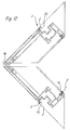
- FIG. 17 Another constructive solution is shown in FIG. 17, in which the punches 32 and 33 are mounted in the device parts 4 which limit the weld bead or form side dishes.
- the punches 32, 33 are by springs acting in the direction of the miter corner 34.35 charged. In the operating position shown, i.e. during the heating process by means of the welding mirror 5, the punches 32, 33 are located with their mitred corners facing end at the welding mirror. After removing the Welding mirror and the merging of the plasticized frame profiles to actual welding process then hit the punch with its miter corner facing end faces against each other and ensure a flush Covering the inner contour of the seals in the miter area.
Landscapes
- Engineering & Computer Science (AREA)
- Mechanical Engineering (AREA)
- Civil Engineering (AREA)
- Structural Engineering (AREA)
- Lining Or Joining Of Plastics Or The Like (AREA)
- Joining Of Corner Units Of Frames Or Wings (AREA)
- Wing Frames And Configurations (AREA)
- Butt Welding And Welding Of Specific Article (AREA)
Applications Claiming Priority (2)
| Application Number | Priority Date | Filing Date | Title |
|---|---|---|---|
| DE19644183 | 1996-10-24 | ||
| DE1996144183 DE19644183A1 (de) | 1996-10-24 | 1996-10-24 | Verfahren und Vorrichtung zum Verschweißen von auf Gehrung geschnittenen Rahmenprofilen aus Kunststoff mit eingezogenen Dichtungen |
Publications (4)
| Publication Number | Publication Date |
|---|---|
| EP0838324A2 true EP0838324A2 (fr) | 1998-04-29 |
| EP0838324A3 EP0838324A3 (fr) | 2000-03-08 |
| EP0838324B1 EP0838324B1 (fr) | 2005-02-16 |
| EP0838324B2 EP0838324B2 (fr) | 2008-07-09 |
Family
ID=7809850
Family Applications (1)
| Application Number | Title | Priority Date | Filing Date |
|---|---|---|---|
| EP19970117744 Expired - Lifetime EP0838324B2 (fr) | 1996-10-24 | 1997-10-14 | Procédé et appareil pour le soudage de profilés, coupés en onglet et comportant des joints d'étanchéité incorporés, pour la fabrication de cadres en matière plastique |
Country Status (13)
| Country | Link |
|---|---|
| US (2) | US5938888A (fr) |
| EP (1) | EP0838324B2 (fr) |
| AT (1) | ATE289257T1 (fr) |
| CA (1) | CA2219143C (fr) |
| CZ (1) | CZ292208B6 (fr) |
| DE (2) | DE19644183A1 (fr) |
| EE (1) | EE03813B1 (fr) |
| ES (1) | ES2236777T5 (fr) |
| HU (1) | HU221878B1 (fr) |
| PL (1) | PL184829B1 (fr) |
| RU (1) | RU2183160C2 (fr) |
| SK (1) | SK284097B6 (fr) |
| UA (1) | UA48173C2 (fr) |
Cited By (5)
| Publication number | Priority date | Publication date | Assignee | Title |
|---|---|---|---|---|
| EP1072392A1 (fr) * | 1999-07-28 | 2001-01-31 | SCHÜCO International KG | Procédé et appareil pour le soudage de profilés coupés en onglet pour la fabrication de cadres en matière plastique |
| GB2353816A (en) * | 1999-09-03 | 2001-03-07 | Permacell Finesse Ltd | Method of and apparatus for welding door or window frame with fitted seals held in compression during the welding process |
| EP2284349A1 (fr) | 2009-07-09 | 2011-02-16 | REHAU AG + Co | Profil en plastique pour un module d'encadrement et module d'encadrement comprenant un tel profil en plastique |
| CN106142536A (zh) * | 2016-08-27 | 2016-11-23 | 安徽万朗磁塑股份有限公司 | 一种门封胶套单角焊接模具 |
| DE102016104588A1 (de) | 2016-03-14 | 2017-09-14 | SCHÜCO International KG | Vorrichtung und Verfahren zum Verschweißen von auf Gehrung geschnittenen Rahmenprofilen aus Kunststoff |
Families Citing this family (24)
| Publication number | Priority date | Publication date | Assignee | Title |
|---|---|---|---|---|
| DE19822292C2 (de) * | 1998-05-18 | 2001-05-23 | Deflex Dichtsysteme Gmbh | Verfahren zur Verbindung von Profilholmen zwecks Bildung von Kunststoffrahmen und Verbindung von Profilholmen |
| US6119752A (en) * | 1998-06-09 | 2000-09-19 | Zollinger; Rolf A. | Tool for welding plastic members |
| DE19905334A1 (de) * | 1999-02-09 | 2000-08-10 | Wilhelm Hollinger Maschinenbau | Verfahren und Vorrichtung zum Verschweißen von Rahmenprofilen mit eingezogenen Dichtungen |
| FR2789724B1 (fr) * | 1999-02-11 | 2001-03-16 | Lapeyre | Cadre de fenetre et son procede de fabrication |
| DE10107224A1 (de) * | 2001-02-16 | 2002-08-22 | Daimler Chrysler Ag | Warmbiegen eines thermoplastischen Werkstücks |
| GB2376656A (en) * | 2001-06-21 | 2002-12-24 | Gti Kombimatec Machines Ltd | Removing notches from the weld face areas of components, to locally reduce waste sprue produced during thermal bonding, apparatus, method & preparation |
| DE10146602C1 (de) * | 2001-09-21 | 2002-12-12 | Deflex Dichtsysteme Gmbh | Verfahren zur Herstellung von Rahmen für Fenster oder Türen |
| CA2373890C (fr) * | 2002-02-28 | 2006-11-28 | Portes Patio Resiver Inc | Trou de repartition des contraintes pour chassis de fenetre |
| EP1687503A1 (fr) | 2003-11-04 | 2006-08-09 | Bystronic Solution Centre Inc. | Panneau encadre et procede de fabrication associe |
| DE202006002741U1 (de) * | 2006-02-21 | 2007-06-28 | Rehau Ag + Co. | Rahmenbaugruppe |
| DE102007051882A1 (de) | 2007-10-30 | 2009-05-07 | Semperit Ag Holding | Verfahren zum Verschweißen von auf Gehrung geschnittenen Rahmenprofilen für Fenster, Türen oder dergleichen sowie Dichtungsstreifen zur Verwendung bei solchen Rahmenprofilen |
| US7935211B2 (en) * | 2007-12-05 | 2011-05-03 | Lasusa Frank | Corner joinery system and method for PVC windows and polymeric substrates used in building products |
| RU2379184C2 (ru) * | 2008-03-24 | 2010-01-20 | Общество с ограниченной ответственностью "Фимтек-Сервис" | Комплект опорно-крепежных приспособлений для сварки оконных и дверных профилей и рамная цулага, входящая в этот комплект |
| CA2806334A1 (fr) * | 2010-07-28 | 2012-02-02 | Press-Seal Gasket Corporation | Joint d'etancheite de porte de remorque |
| DE202013012778U1 (de) * | 2012-03-07 | 2019-07-31 | Graf Synergy S.R.L. | Vorrichtung zum Verschweißen von profilierten Elementen aus Kunststoffmaterial, insbesondere PVC |
| US9151107B2 (en) | 2013-09-24 | 2015-10-06 | Press-Seal Gasket Corporation | Trailer door seal |
| PT3116704T (pt) * | 2014-03-12 | 2020-05-22 | Salim Kaban | Máquina de soldar cantos de perfis de pvc sem rebarbas |
| DE102015107121B4 (de) | 2015-05-07 | 2019-11-14 | Rotox Besitz-Und Verwaltungsgesellschaft Mbh | Verfahren und Vorrichtung zum Verbinden von Profilteilen |
| DE102016102499A1 (de) * | 2016-02-12 | 2017-08-17 | Rotox Besitz-Und Verwaltungsgesellschaft Mbh | Verfahren und Vorrichtung zum Verbinden von Profilteilen |
| IT201600071193A1 (it) * | 2016-07-07 | 2018-01-07 | Graf Synergy Srl | Macchina per la saldatura di profilati in plastica |
| US10928096B2 (en) | 2017-06-30 | 2021-02-23 | Robert Bosch Llc | Environmental control unit including noise reduction features |
| US10947772B2 (en) | 2017-10-24 | 2021-03-16 | Quaker Window Products Co. | Thermally enhanced multi-component glass doors and windows |
| US10107027B1 (en) | 2017-10-24 | 2018-10-23 | Quaker Window Products Co. | Thermally enhanced multi-component window |
| RU205868U1 (ru) * | 2020-10-12 | 2021-08-11 | Роман Александрович Юрченко | Горячий пресс для производства мягких окон |
Family Cites Families (16)
| Publication number | Priority date | Publication date | Assignee | Title |
|---|---|---|---|---|
| DE2316749C2 (de) * | 1973-04-04 | 1974-12-05 | Otto 5470 Andernach Anschuetz | Außenform zur Verhinderung der Entstehung eines Schweißwulstes beim Stumpfschweißen von Kunststoffprofilen |
| US4183778A (en) * | 1977-11-14 | 1980-01-15 | Etablissements Mesnel | Method of making sealing strip joint |
| DE3405384C1 (de) * | 1984-02-15 | 1985-07-18 | SKS-Stakusit-Stahl-Kunststoff GmbH, 4100 Duisburg | Verfahren und Vorrichtung zum Verschweißen von zwei Kunststoffprofilen zur Rahmenecke eines Fenster- oder Türrahmens |
| DE3408373A1 (de) * | 1984-03-08 | 1986-06-26 | Koeller Gmbh | Verfahren und vorrichtung zur herstellung von eckverbindungen in rahmen aus thermoplastischen, insbesondere hart-pvc-profilen fuer fluegel und rahmen von verglasten tueren und fenstern |
| US4601927A (en) * | 1984-05-11 | 1986-07-22 | Hydroacoustics, Inc. | Welding of plastic parts |
| GB2187529A (en) * | 1986-03-05 | 1987-09-09 | Blacknell Buildings Ltd | Building frame assembly |
| DE3614673A1 (de) * | 1986-04-30 | 1987-11-05 | Urban Maschinenbau | Verfahren und vorrichtung zur herstellung von fensterrahmen od. dgl. |
| IT1236247B (it) * | 1989-11-14 | 1993-01-27 | Finstral Spa | Profilati estrusi in materiale plastico dotati di guarnizioni riportate per estrusione e sistema di giunzione di questi |
| US5240537A (en) * | 1991-07-01 | 1993-08-31 | Namic U.S.A. Corporation | Method for manufacturing a soft tip catheter |
| DE9111119U1 (de) * | 1991-09-07 | 1991-11-14 | Kommanditgesellschaft Hassomat Maschinenbau GmbH & Co, 2000 Hamburg | Vorrichtung zum Verschweißen von Profilen aus Kunststoff |
| DE4138352C2 (de) * | 1991-11-21 | 2000-03-16 | Stuertz Maschbau | Verfahren und Vorrichtung zur Herstellung von rechteckigen Rahmen |
| JP2583479B2 (ja) * | 1992-06-30 | 1997-02-19 | 株式会社イノアックコーポレーション | 合成樹脂モールの端末接合方法および装置 |
| US5385628A (en) * | 1993-03-24 | 1995-01-31 | Davis; Roland | Gasket welding apparatus and method |
| DE4323728C2 (de) * | 1993-07-15 | 1998-08-20 | Wegoma Maschf Gmbh | Schweißvorrichtung für rechteckige Rahmen, insbesondere Fensterrahmen |
| US5614052A (en) * | 1994-12-21 | 1997-03-25 | Gencorp Inc. | Vacuum retention gasket splicing |
| DE19545480C1 (de) * | 1995-12-06 | 1996-10-31 | Deflex Dichtsysteme Gmbh | Verfahren zum Verschweißen der Profilholme eines Kunststoffrahmens aus Hart-PVC zusammen mit Dichtsträngen aus Plastomeren und Vorrichtungen zur Durchführung der Verfahren |
-
1996
- 1996-10-24 DE DE1996144183 patent/DE19644183A1/de not_active Withdrawn
-
1997
- 1997-10-14 ES ES97117744T patent/ES2236777T5/es not_active Expired - Lifetime
- 1997-10-14 DE DE59712202T patent/DE59712202D1/de not_active Expired - Lifetime
- 1997-10-14 AT AT97117744T patent/ATE289257T1/de not_active IP Right Cessation
- 1997-10-14 EP EP19970117744 patent/EP0838324B2/fr not_active Expired - Lifetime
- 1997-10-17 PL PL97322677A patent/PL184829B1/pl not_active IP Right Cessation
- 1997-10-20 HU HU9701667A patent/HU221878B1/hu not_active IP Right Cessation
- 1997-10-21 US US08/955,212 patent/US5938888A/en not_active Expired - Fee Related
- 1997-10-22 CZ CZ19973344A patent/CZ292208B6/cs not_active IP Right Cessation
- 1997-10-23 RU RU97117465A patent/RU2183160C2/ru not_active IP Right Cessation
- 1997-10-23 EE EE9700284A patent/EE03813B1/xx not_active IP Right Cessation
- 1997-10-23 CA CA 2219143 patent/CA2219143C/fr not_active Expired - Fee Related
- 1997-10-24 UA UA97105205A patent/UA48173C2/uk unknown
- 1997-10-24 SK SK1448-97A patent/SK284097B6/sk unknown
-
1999
- 1999-01-20 US US09/234,211 patent/US6129805A/en not_active Expired - Fee Related
Cited By (6)
| Publication number | Priority date | Publication date | Assignee | Title |
|---|---|---|---|---|
| EP1072392A1 (fr) * | 1999-07-28 | 2001-01-31 | SCHÜCO International KG | Procédé et appareil pour le soudage de profilés coupés en onglet pour la fabrication de cadres en matière plastique |
| GB2353816A (en) * | 1999-09-03 | 2001-03-07 | Permacell Finesse Ltd | Method of and apparatus for welding door or window frame with fitted seals held in compression during the welding process |
| EP2284349A1 (fr) | 2009-07-09 | 2011-02-16 | REHAU AG + Co | Profil en plastique pour un module d'encadrement et module d'encadrement comprenant un tel profil en plastique |
| DE102016104588A1 (de) | 2016-03-14 | 2017-09-14 | SCHÜCO International KG | Vorrichtung und Verfahren zum Verschweißen von auf Gehrung geschnittenen Rahmenprofilen aus Kunststoff |
| EP3219465A1 (fr) | 2016-03-14 | 2017-09-20 | SCHÜCO International KG | Dispositif et procédé de soudage de profilés de cadre en plastique découpés en onglet |
| CN106142536A (zh) * | 2016-08-27 | 2016-11-23 | 安徽万朗磁塑股份有限公司 | 一种门封胶套单角焊接模具 |
Also Published As
| Publication number | Publication date |
|---|---|
| DE59712202D1 (de) | 2005-03-24 |
| HU9701667D0 (en) | 1997-12-29 |
| HUP9701667A2 (hu) | 1998-05-28 |
| RU2183160C2 (ru) | 2002-06-10 |
| EP0838324B2 (fr) | 2008-07-09 |
| CZ292208B6 (cs) | 2003-08-13 |
| PL184829B1 (pl) | 2002-12-31 |
| EP0838324B1 (fr) | 2005-02-16 |
| SK144897A3 (en) | 1998-05-06 |
| US6129805A (en) | 2000-10-10 |
| SK284097B6 (sk) | 2004-09-08 |
| CZ334497A3 (cs) | 1999-02-17 |
| CA2219143C (fr) | 2006-07-11 |
| DE19644183A1 (de) | 1998-04-30 |
| PL322677A1 (en) | 1998-04-27 |
| EE9700284A (et) | 1998-06-15 |
| CA2219143A1 (fr) | 1998-04-24 |
| HUP9701667A3 (en) | 2001-02-28 |
| EE03813B1 (et) | 2002-08-15 |
| ES2236777T3 (es) | 2005-07-16 |
| US5938888A (en) | 1999-08-17 |
| ES2236777T5 (es) | 2008-12-16 |
| HU221878B1 (hu) | 2003-02-28 |
| UA48173C2 (uk) | 2002-08-15 |
| EP0838324A3 (fr) | 2000-03-08 |
| ATE289257T1 (de) | 2005-03-15 |
Similar Documents
| Publication | Publication Date | Title |
|---|---|---|
| EP0838324B2 (fr) | Procédé et appareil pour le soudage de profilés, coupés en onglet et comportant des joints d'étanchéité incorporés, pour la fabrication de cadres en matière plastique | |
| DE69000238T2 (de) | Anordnung fuer buendig verschiebbare scheiben fuer kraftfahrzeugtueren. | |
| DE19531167C2 (de) | Kraftfahrzeug-Dichtungsprofil | |
| DE4015766A1 (de) | Dichtung fuer container, insbesondere kuehlcontainer | |
| DE3702402A1 (de) | Hoehenverschiebbare seitenscheibe fuer kraftfahrzeuge | |
| EP0428077B1 (fr) | Procédé d'assemblage de profilés pour fenêtres en matière plastique avec joints d'étanchéité co-extrudés | |
| DE69808045T2 (de) | Verfahren und Vorrichtung zum thermischen Verbinden von Elementen zum Formen eines Rahmens | |
| DE3221594C2 (fr) | ||
| DE9319329U1 (de) | Werkzeug zur Montage von Leisten | |
| DE2906934A1 (de) | Gummi-profilrahmen | |
| EP0404199A1 (fr) | Profilé en matière élastomère | |
| DE69713123T2 (de) | Fahrzeugscheibe | |
| EP0155641B1 (fr) | Dispositif de guidage et de retenue d'un vitre mobile dans le cadre de vitre d'un véhicule automobile | |
| EP0277569B1 (fr) | Battant de porte de boîtier ou d'armoire pour le montage d'appareils électriques et son procédé de fabrication | |
| DE3920925C2 (de) | Formwerkzeug zum Herstellen (Umschäumen) eines Profiles aus Mehrkomponenten-Kunststoff, insbesondere Polyurethan, am Rand einer Glasscheibe | |
| DE69903209T2 (de) | Dichtungselement für Schiebefenster, insbesondere für eine Kraftfahrzeugtür und Verfahren zu deren Herstellung | |
| DE69720009T3 (de) | Dichtungssystem für bewegliches Fenster | |
| DE2061716B2 (de) | Dichtung für Fenster, Türen o.dgl | |
| AT393534B (de) | Dichtungs-formstueck | |
| DE2208192A1 (de) | Magnetischer Dichtungsstreifen | |
| DE2232112C2 (de) | Fenster, Tür od. dgl. | |
| DE19612285A1 (de) | Verfahren zur Herstellung von Fensterrahmen aus Kunststoff | |
| DE69504161T2 (de) | Verfahren zur Herstellung eines mit metallischer Armatur ausgerüsteten, extrudierten Dichtungsprofils für Kraftfahrzeuge. | |
| DE4033660A1 (de) | Verfahren und vorrichtung zur randfugenversiegelung einer isolierglaseinheit, insbesondere einer kraftfahrzeug-isolierglaseinheit | |
| DE29906387U1 (de) | Montagegerät zum Einführen einer Gummidichtung |
Legal Events
| Date | Code | Title | Description |
|---|---|---|---|
| PUAI | Public reference made under article 153(3) epc to a published international application that has entered the european phase |
Free format text: ORIGINAL CODE: 0009012 |
|
| AK | Designated contracting states |
Kind code of ref document: A2 Designated state(s): AT BE CH DE DK ES FI FR GB IT LI LU NL SE |
|
| AX | Request for extension of the european patent |
Free format text: LT PAYMENT 971014;LV PAYMENT 971014;SI PAYMENT 971014 |
|
| 17P | Request for examination filed |
Effective date: 19990420 |
|
| PUAL | Search report despatched |
Free format text: ORIGINAL CODE: 0009013 |
|
| AK | Designated contracting states |
Kind code of ref document: A3 Designated state(s): AT BE CH DE DK ES FI FR GB GR IE IT LI LU MC NL PT SE |
|
| AX | Request for extension of the european patent |
Free format text: LT PAYMENT 19971014;LV PAYMENT 19971014;SI PAYMENT 19971014 |
|
| RIC1 | Information provided on ipc code assigned before grant |
Free format text: 7B 29C 65/20 A, 7E 06B 3/96 B, 7B 29C 65/00 B |
|
| AKX | Designation fees paid |
Free format text: AT BE CH DE DK ES FI FR GB IT LI LU NL SE |
|
| AXX | Extension fees paid |
Free format text: LT PAYMENT 19971014;LV PAYMENT 19971014;SI PAYMENT 19971014 |
|
| 17Q | First examination report despatched |
Effective date: 20021023 |
|
| GRAP | Despatch of communication of intention to grant a patent |
Free format text: ORIGINAL CODE: EPIDOSNIGR1 |
|
| GRAS | Grant fee paid |
Free format text: ORIGINAL CODE: EPIDOSNIGR3 |
|
| GRAA | (expected) grant |
Free format text: ORIGINAL CODE: 0009210 |
|
| AK | Designated contracting states |
Kind code of ref document: B1 Designated state(s): AT BE CH DE DK ES FI FR GB IT LI LU NL SE |
|
| AX | Request for extension of the european patent |
Extension state: LT LV SI |
|
| REG | Reference to a national code |
Ref country code: GB Ref legal event code: FG4D Free format text: NOT ENGLISH |
|
| REG | Reference to a national code |
Ref country code: CH Ref legal event code: NV Representative=s name: ISLER & PEDRAZZINI AG Ref country code: CH Ref legal event code: EP |
|
| REF | Corresponds to: |
Ref document number: 59712202 Country of ref document: DE Date of ref document: 20050324 Kind code of ref document: P |
|
| PG25 | Lapsed in a contracting state [announced via postgrant information from national office to epo] |
Ref country code: DK Free format text: LAPSE BECAUSE OF FAILURE TO SUBMIT A TRANSLATION OF THE DESCRIPTION OR TO PAY THE FEE WITHIN THE PRESCRIBED TIME-LIMIT Effective date: 20050516 |
|
| REG | Reference to a national code |
Ref country code: SE Ref legal event code: TRGR |
|
| REG | Reference to a national code |
Ref country code: ES Ref legal event code: FG2A Ref document number: 2236777 Country of ref document: ES Kind code of ref document: T3 |
|
| GBT | Gb: translation of ep patent filed (gb section 77(6)(a)/1977) |
Effective date: 20050727 |
|
| PGFP | Annual fee paid to national office [announced via postgrant information from national office to epo] |
Ref country code: FI Payment date: 20051021 Year of fee payment: 9 |
|
| PGFP | Annual fee paid to national office [announced via postgrant information from national office to epo] |
Ref country code: SE Payment date: 20051024 Year of fee payment: 9 |
|
| PG25 | Lapsed in a contracting state [announced via postgrant information from national office to epo] |
Ref country code: LU Free format text: LAPSE BECAUSE OF NON-PAYMENT OF DUE FEES Effective date: 20051031 |
|
| PLBI | Opposition filed |
Free format text: ORIGINAL CODE: 0009260 |
|
| PLAX | Notice of opposition and request to file observation + time limit sent |
Free format text: ORIGINAL CODE: EPIDOSNOBS2 |
|
| 26 | Opposition filed |
Opponent name: REHAU AG & CO. Effective date: 20051116 Opponent name: URBAN GMBH & CO. MASCHINENBAU KG Effective date: 20051115 |
|
| ET | Fr: translation filed | ||
| NLR1 | Nl: opposition has been filed with the epo |
Opponent name: REHAU AG & CO. Opponent name: URBAN GMBH & CO. MASCHINENBAU KG |
|
| PLAF | Information modified related to communication of a notice of opposition and request to file observations + time limit |
Free format text: ORIGINAL CODE: EPIDOSCOBS2 |
|
| PLAF | Information modified related to communication of a notice of opposition and request to file observations + time limit |
Free format text: ORIGINAL CODE: EPIDOSCOBS2 |
|
| PLBB | Reply of patent proprietor to notice(s) of opposition received |
Free format text: ORIGINAL CODE: EPIDOSNOBS3 |
|
| PG25 | Lapsed in a contracting state [announced via postgrant information from national office to epo] |
Ref country code: FI Free format text: LAPSE BECAUSE OF NON-PAYMENT OF DUE FEES Effective date: 20061014 |
|
| PG25 | Lapsed in a contracting state [announced via postgrant information from national office to epo] |
Ref country code: SE Free format text: LAPSE BECAUSE OF NON-PAYMENT OF DUE FEES Effective date: 20061015 |
|
| PGFP | Annual fee paid to national office [announced via postgrant information from national office to epo] |
Ref country code: IT Payment date: 20061031 Year of fee payment: 10 |
|
| EUG | Se: european patent has lapsed | ||
| LTLA | Lt: lapse of european patent or patent extension |
Effective date: 20061014 |
|
| PLAB | Opposition data, opponent's data or that of the opponent's representative modified |
Free format text: ORIGINAL CODE: 0009299OPPO |
|
| REG | Reference to a national code |
Ref country code: CH Ref legal event code: PCAR Free format text: ISLER & PEDRAZZINI AG;POSTFACH 1772;8027 ZUERICH (CH) |
|
| R26 | Opposition filed (corrected) |
Opponent name: REHAU AG & CO. Effective date: 20051116 Opponent name: URBAN GMBH & CO. MASCHINENBAU KG Effective date: 20051115 |
|
| NLR1 | Nl: opposition has been filed with the epo |
Opponent name: REHAU AG & CO. Opponent name: URBAN GMBH & CO. MASCHINENBAU KG |
|
| PGFP | Annual fee paid to national office [announced via postgrant information from national office to epo] |
Ref country code: ES Payment date: 20071026 Year of fee payment: 11 |
|
| PUAH | Patent maintained in amended form |
Free format text: ORIGINAL CODE: 0009272 |
|
| STAA | Information on the status of an ep patent application or granted ep patent |
Free format text: STATUS: PATENT MAINTAINED AS AMENDED |
|
| 27A | Patent maintained in amended form |
Effective date: 20080709 |
|
| AK | Designated contracting states |
Kind code of ref document: B2 Designated state(s): AT BE CH DE DK ES FI FR GB IT LI LU NL SE |
|
| AX | Request for extension of the european patent |
Extension state: LT LV SI |
|
| REG | Reference to a national code |
Ref country code: CH Ref legal event code: AEN Free format text: AUFRECHTERHALTUNG DES PATENTES IN GEAENDERTER FORM |
|
| NLR2 | Nl: decision of opposition |
Effective date: 20080709 |
|
| REG | Reference to a national code |
Ref country code: ES Ref legal event code: DC2A Date of ref document: 20080929 Kind code of ref document: T5 |
|
| NLR3 | Nl: receipt of modified translations in the netherlands language after an opposition procedure | ||
| PG25 | Lapsed in a contracting state [announced via postgrant information from national office to epo] |
Ref country code: IT Free format text: LAPSE BECAUSE OF NON-PAYMENT OF DUE FEES Effective date: 20071014 |
|
| REG | Reference to a national code |
Ref country code: ES Ref legal event code: FD2A Effective date: 20081015 |
|
| PG25 | Lapsed in a contracting state [announced via postgrant information from national office to epo] |
Ref country code: ES Free format text: LAPSE BECAUSE OF NON-PAYMENT OF DUE FEES Effective date: 20081015 |
|
| PGFP | Annual fee paid to national office [announced via postgrant information from national office to epo] |
Ref country code: CH Payment date: 20091026 Year of fee payment: 13 Ref country code: AT Payment date: 20091022 Year of fee payment: 13 |
|
| PGFP | Annual fee paid to national office [announced via postgrant information from national office to epo] |
Ref country code: NL Payment date: 20091027 Year of fee payment: 13 |
|
| PGFP | Annual fee paid to national office [announced via postgrant information from national office to epo] |
Ref country code: GB Payment date: 20091023 Year of fee payment: 13 Ref country code: FR Payment date: 20091110 Year of fee payment: 13 |
|
| PGFP | Annual fee paid to national office [announced via postgrant information from national office to epo] |
Ref country code: BE Payment date: 20091029 Year of fee payment: 13 |
|
| PGFP | Annual fee paid to national office [announced via postgrant information from national office to epo] |
Ref country code: DE Payment date: 20101026 Year of fee payment: 14 |
|
| BERE | Be: lapsed |
Owner name: *SCHUCO INTERNATIONAL K.G. Effective date: 20101031 |
|
| REG | Reference to a national code |
Ref country code: NL Ref legal event code: V1 Effective date: 20110501 |
|
| REG | Reference to a national code |
Ref country code: CH Ref legal event code: PL |
|
| GBPC | Gb: european patent ceased through non-payment of renewal fee |
Effective date: 20101014 |
|
| PG25 | Lapsed in a contracting state [announced via postgrant information from national office to epo] |
Ref country code: LI Free format text: LAPSE BECAUSE OF NON-PAYMENT OF DUE FEES Effective date: 20101031 Ref country code: FR Free format text: LAPSE BECAUSE OF NON-PAYMENT OF DUE FEES Effective date: 20101102 Ref country code: CH Free format text: LAPSE BECAUSE OF NON-PAYMENT OF DUE FEES Effective date: 20101031 |
|
| REG | Reference to a national code |
Ref country code: FR Ref legal event code: ST Effective date: 20110630 |
|
| PG25 | Lapsed in a contracting state [announced via postgrant information from national office to epo] |
Ref country code: BE Free format text: LAPSE BECAUSE OF NON-PAYMENT OF DUE FEES Effective date: 20101031 Ref country code: GB Free format text: LAPSE BECAUSE OF NON-PAYMENT OF DUE FEES Effective date: 20101014 Ref country code: AT Free format text: LAPSE BECAUSE OF NON-PAYMENT OF DUE FEES Effective date: 20101014 Ref country code: NL Free format text: LAPSE BECAUSE OF NON-PAYMENT OF DUE FEES Effective date: 20110501 |
|
| PG25 | Lapsed in a contracting state [announced via postgrant information from national office to epo] |
Ref country code: DE Free format text: LAPSE BECAUSE OF NON-PAYMENT OF DUE FEES Effective date: 20120501 |
|
| REG | Reference to a national code |
Ref country code: DE Ref legal event code: R119 Ref document number: 59712202 Country of ref document: DE Effective date: 20120501 |